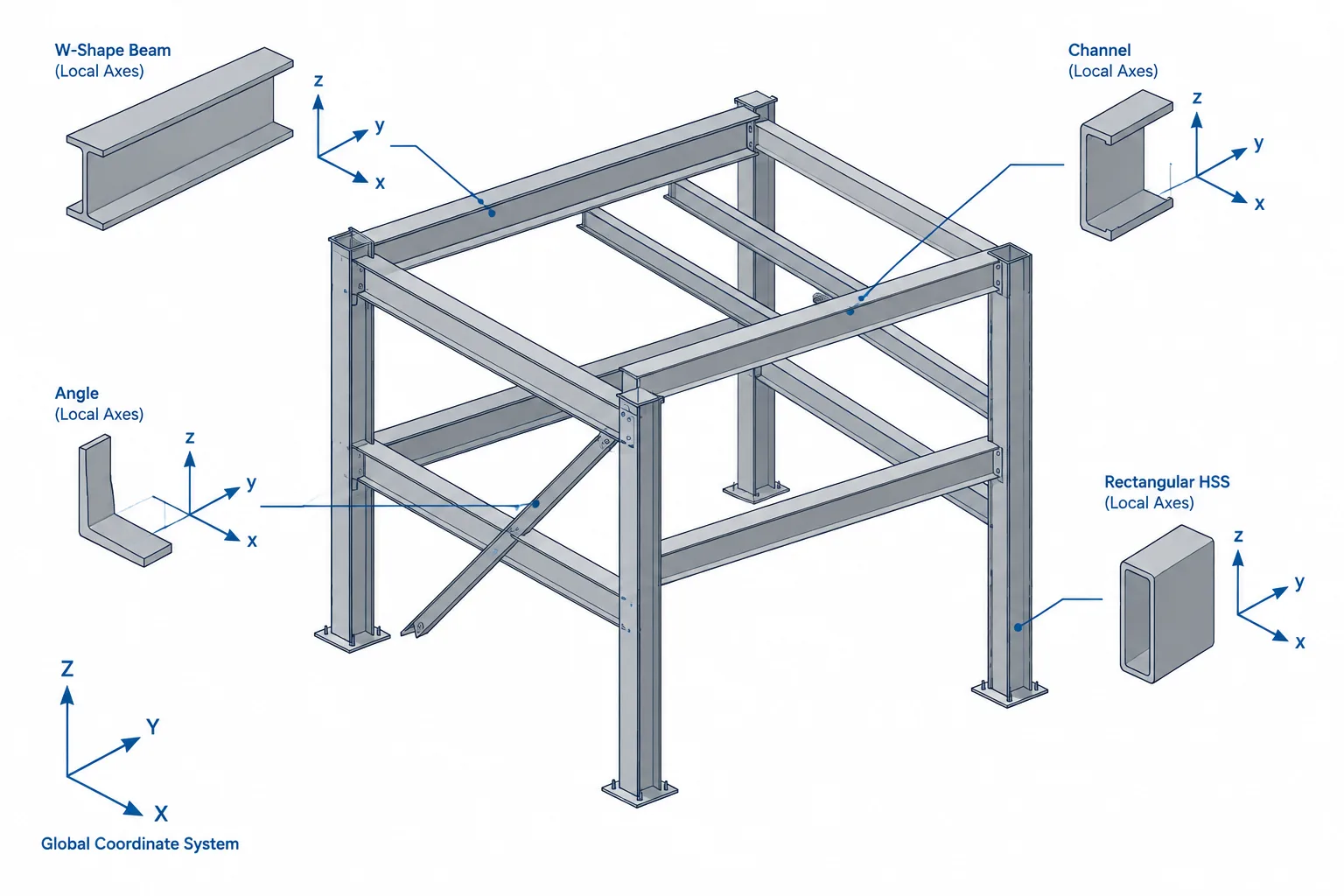
A structural steel member in a CAD or building model has more than a shape designation and two endpoints. It also has a direction, a section orientation, and a relationship to the project coordinate system. These relationships are commonly described with global axes, member local axes, section axes, insertion lines, and rotation values.
Confusing these references can rotate a channel the wrong way, reverse an angle connection, place a beam offset on the incorrect side, or cause connection components to appear at the wrong end. The geometry may still look reasonable in one view, which makes axis-related errors especially difficult to detect.
The exact axis labels and positive directions vary among CAD, analysis, detailing, and fabrication systems. The practical goal is therefore not to memorize one software convention. It is to understand the underlying geometry and verify how each project platform represents it.
Global axes and local axes serve different purposes
Global axes provide a fixed coordinate system for the entire project. They establish directions and elevations used to locate grids, levels, members, plates, and other objects. A global vertical axis, for example, remains vertical regardless of how an individual beam is oriented.
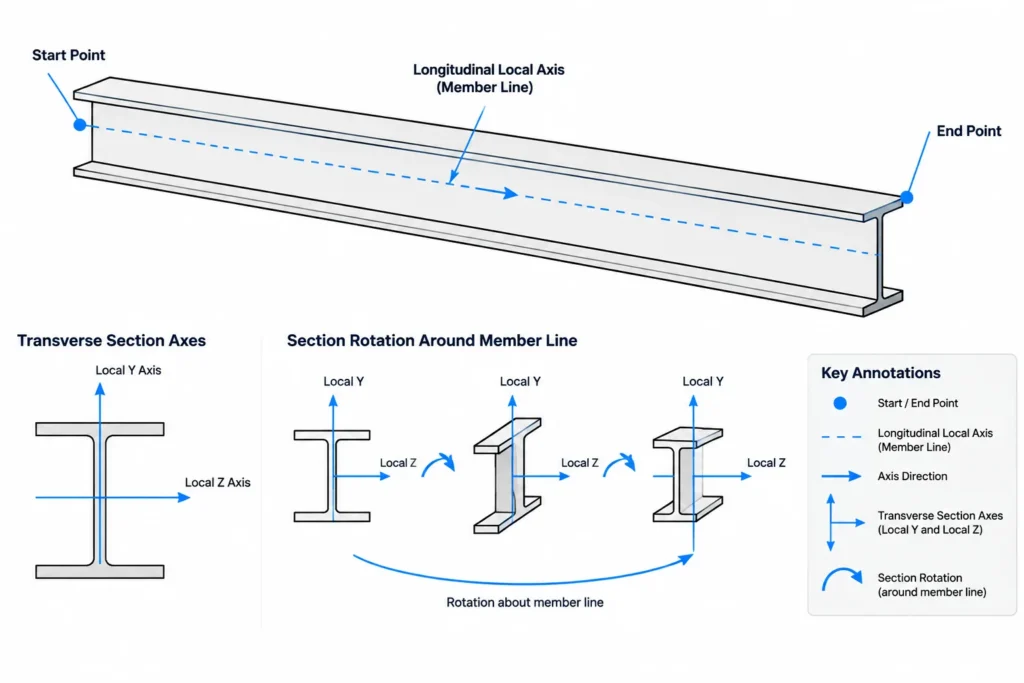
Local axes move and rotate with an object. For a linear steel member, one local axis usually follows the member from one endpoint to the other. The remaining local axes describe the orientation of the cross-section around that longitudinal line.
A horizontal beam aligned with a project grid may have local and global directions that are easy to compare. A skewed brace or sloping rafter will not. Its longitudinal local axis follows the member even though that direction has components along several global axes.
Three references that should not be treated as interchangeable
Member direction
Member direction is established by the relationship between the member’s start and end points. Reversing those points may leave the visible body in the same physical location, but it can change information that depends on direction, including:
- Start-end connection assignments
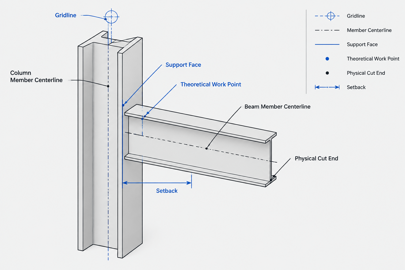
- End offsets and setbacks
- Component orientation
- Cut or cope definitions
- Local coordinate signs
- Assembly or drawing-view behavior
This is why visually identical members are not always digitally equivalent.
Section rotation
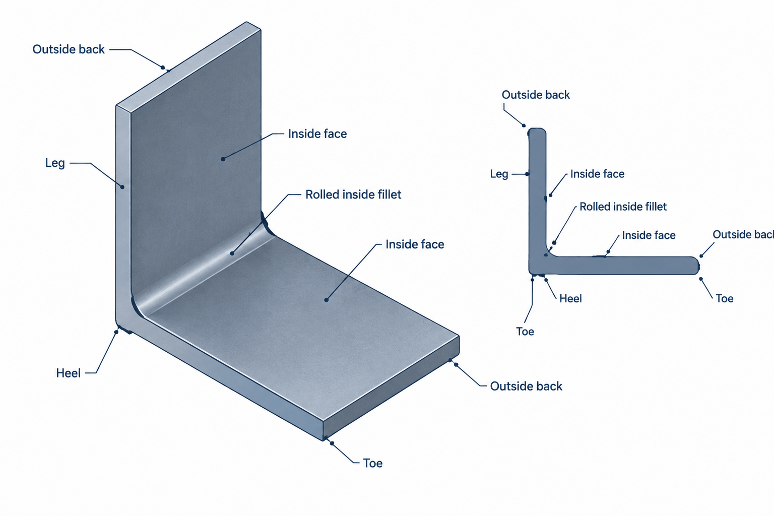
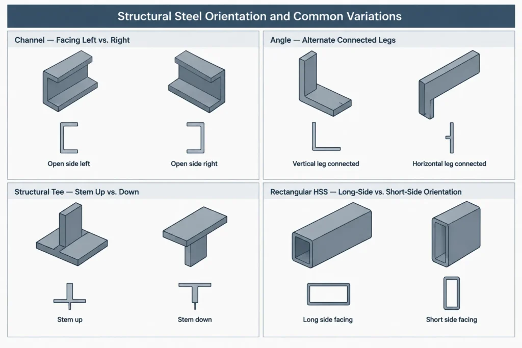
Section rotation describes how the cross-section is turned around the member’s longitudinal axis. A W-shape can have its web vertical or horizontal. A channel can face either side. An angle can have either leg up, down, inward, or outward. These conditions are controlled by section rotation and orientation, not merely by the endpoints.
Rotation values must be interpreted in the context of the software’s local-axis convention. A positive rotation viewed from the start toward the end may not match a value imported from a system using the opposite viewing direction.
Insertion or reference line
The line used to place a member may pass through its centroid, geometric center, top flange, outside face, or another selected reference location. Some workflows also apply offsets between the reference line and the physical section.
As a result, a correctly rotated shape can still be incorrectly located. Rotation answers how the section is turned; insertion and offsets answer where it sits relative to the positioning line.
Section-table axes are not automatically model axes
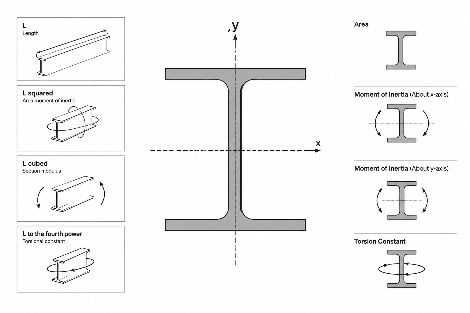
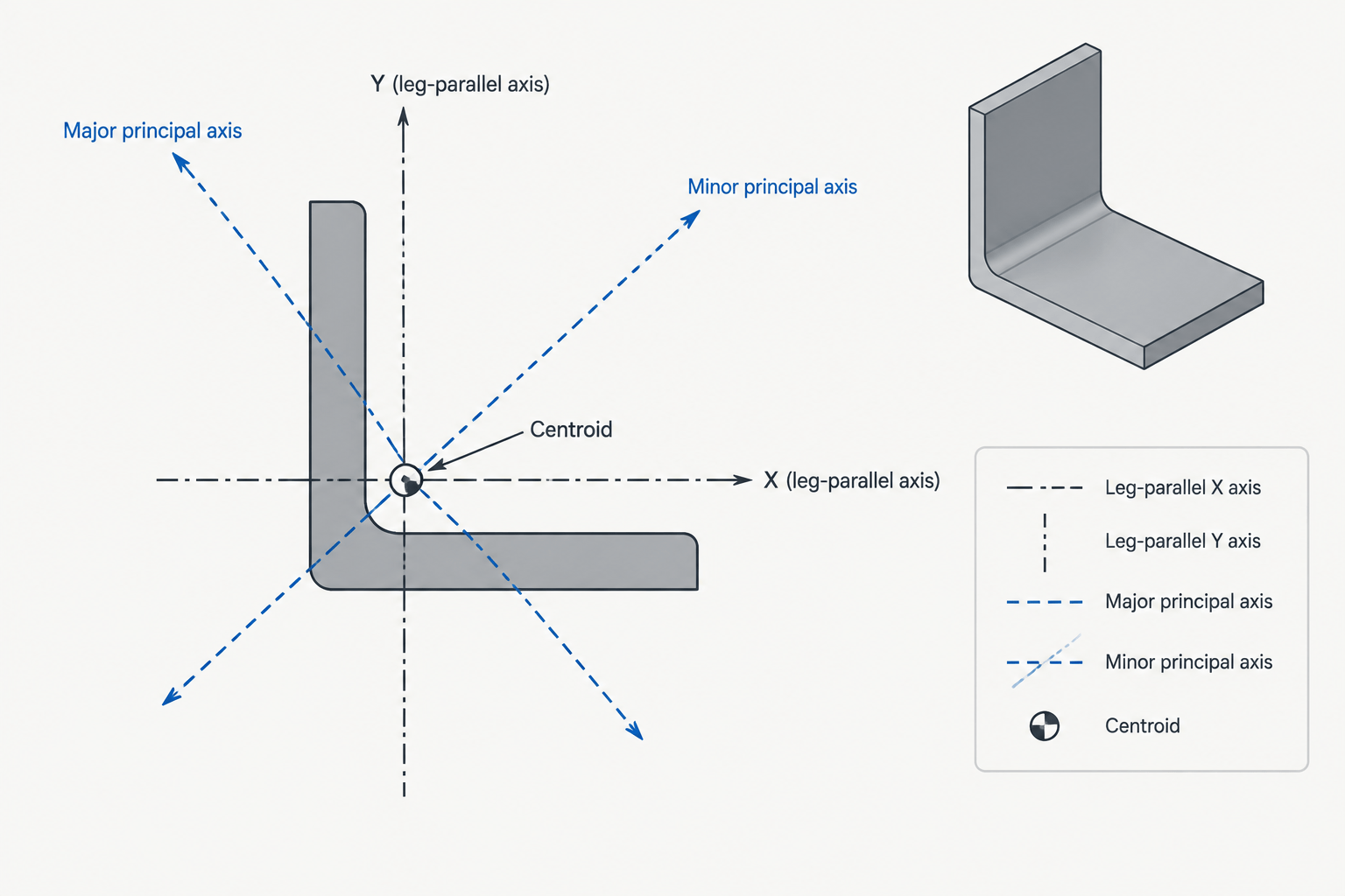
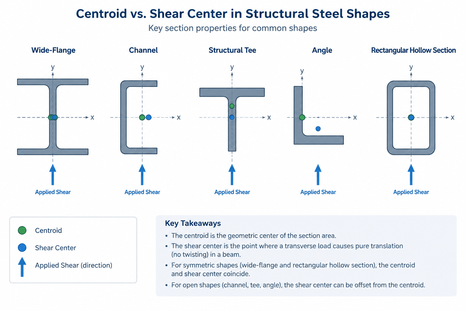
Published shape tables commonly identify section-property axes such as x-x and y-y. For doubly symmetric I-shaped sections, these correspond to the familiar strong and weak bending axes. Those labels describe properties of the cross-section. They do not guarantee that a modeling program’s local y and local z axes use the same labels or directions.
This distinction becomes more important with channels, angles, tees, and other sections that are not doubly symmetric. An angle may have geometric reference axes as well as rotated principal axes. A channel’s centroidal axes do not eliminate its directional characteristics. Simply seeing an x, y, or z label in two different sources is not enough to establish equivalence.
Before transferring loads, offsets, rotations, or section properties between systems, confirm:
- Which local axis runs along the member
- How the transverse local axes are oriented
- Where the section origin is located
- Whether rotations follow a right-hand or another documented convention
- Whether section properties are reported about geometric, centroidal, or principal axes
Why asymmetric shapes reveal axis errors quickly
Doubly symmetric shapes can conceal direction problems because some rotations or endpoint reversals produce similar-looking geometry. Asymmetric and singly symmetric sections are less forgiving.
| Shape or assembly | Axis-related issue to verify | Possible coordination consequence |
|---|---|---|
| Channel | Open side and web direction | Connection material or clearance placed on the wrong side |
| Single angle | Connected leg, outstanding leg, and toe direction | Reversed bolt line or mismatched supporting face |
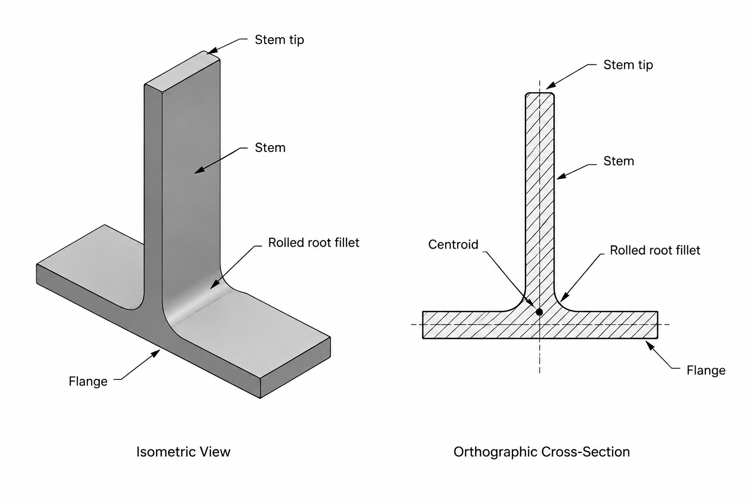
| Structural tee | Stem and flange orientation | Incorrect attachment face or elevation |
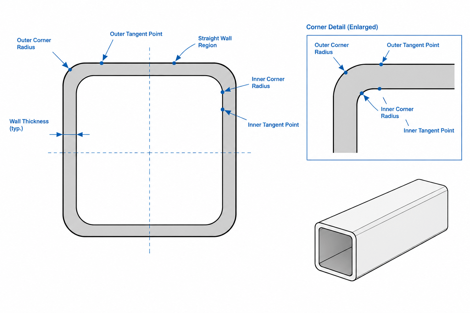
| Rectangular HSS | Long-side and short-side orientation | Plate width, framing face, or architectural alignment conflict |
| Back-to-back pair | Individual section directions and spacing reference | Pair faces inward when the detail requires outward orientation |
| Built-up member | Assembly origin and component local directions | Mirrored plates, stiffeners, or connection components |
Even circular sections, which do not show obvious cross-section rotation, can retain meaningful start-end direction for holes, attachments, end treatments, and data exchange.
Sloped and skewed members need an orientation rule
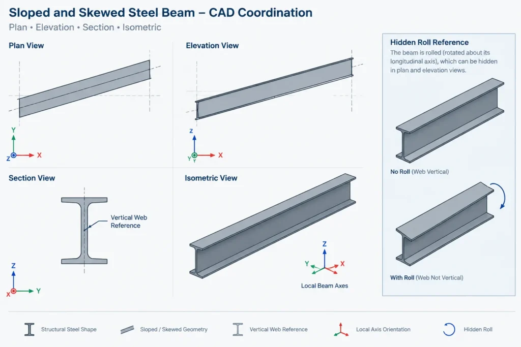
For a member lying in a simple horizontal plane, a default vertical reference may produce the expected web orientation. Problems arise when the member slopes, is skewed in plan, or approaches a near-vertical position. The software must determine how to construct the transverse local axes around the member line.
A useful project workflow states the intended physical result rather than relying only on a rotation value. Examples include keeping a beam web vertical, keeping a rectangular HSS face parallel to a roof plane, or orienting an angle leg toward a supporting member. The numerical rotation is then a model input used to achieve that condition, not the primary definition communicated to reviewers.
Compound geometry deserves a section or 3D check. A plan view may confirm the member line but hide an unintended roll. An elevation may show the slope while concealing whether a channel faces inward or outward.
Mirroring is not the same as rotating
Mirroring can change handedness. Rotation moves an object around an axis without necessarily changing the relationship among its defining directions. A mirrored connection may therefore look similar to a rotated connection while having different plate faces, hole references, weld sides, or start-end assignments.
This matters when copying framing between opposite sides of a building. After mirroring, inspect asymmetric members and connection components instead of assuming the copied objects remain logically correct. Check both physical geometry and object data.
A practical axis-checking workflow
- Identify the global project directions. Confirm the model’s plan directions and vertical direction before reviewing local member coordinates.
- Display or interrogate member endpoints. Determine which endpoint the system treats as the start and which it treats as the end.
- Display local axes when available. Use a simple test member if the axis colors, labels, or arrows are unfamiliar.
- Confirm the section origin. Determine whether the reference line passes through the centroid, geometric center, flange, face, or another insertion point.
- Check the physical orientation. For a channel, identify the open side. For an angle, identify both legs and the toe. For an I-shaped section, identify the web and flange planes.
- Review offsets separately from rotation. Do not use a compensating rotation to solve an insertion-line problem, or an offset to disguise an incorrect section orientation.
- Test one connection or attachment. A sample plate, hole group, or end component can reveal a reversed local direction before the condition is repeated.
- Inspect multiple views. Use plan, elevation, section, and 3D views as appropriate.
- Recheck after exchange or conversion. Imported geometry may preserve appearance while losing object intelligence, axis definitions, or editable orientation data.
Information worth communicating on drawings
Shop and erection drawings generally need to communicate the resulting physical condition, not a software-specific local-axis value. Show the orientation that affects fabrication or erection through clear views, sections, dimensions, elevations, face references, and connection details.
For ambiguous members, useful communication may include:
- Which channel side is open
- Which angle leg is connected
- Whether a tee stem points up or down
- Which HSS face receives an attachment
- Whether offsets are measured to a centerline, face, or edge
- Which end receives a particular cut, plate, or hole pattern
Internal modeling conventions should also be documented for the project team, especially when several applications exchange member data.
Final coordination principle
Structural steel local axes are a data framework for describing member direction and cross-section orientation. They are not a substitute for checking the actual steel geometry. A reliable review asks four separate questions: Where is the member line? Which end is the start? How is the section rotated? Where is the section positioned relative to the line?
When those questions are answered independently, shape data, CAD geometry, connections, and drawings are much more likely to remain coordinated—even for sloped members, asymmetric sections, mirrored framing, and multi-platform model exchanges.