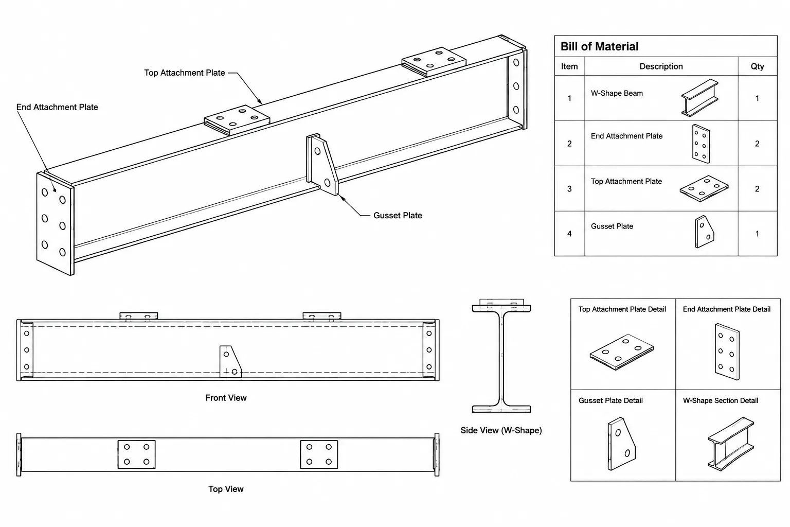
End-plate connections use a plate welded to the end of a steel member and bolted to a supporting member. Although the concept appears simple, the plate outline, bolt arrangement, weld access, supporting surface, and member end condition must all work together. One of the first distinctions a drafter encounters is whether the plate is flush with the connected member or extends beyond it.
The difference between flush and extended end-plate connections is primarily geometric, but geometry affects fabrication, erection, force transfer, and drawing clarity. A connection should not be classified or detailed from appearance alone. The engineer’s connection design, project specifications, and fabricator requirements control the final plate, bolts, welds, and supporting-member checks.
What Is an End-Plate Connection?
An end plate is attached to the end of a beam, brace, HSS member, or other framing element. During erection, the plate is positioned against a supporting flange, web, column face, or another connection plate and secured with bolts. The plate can serve different structural purposes depending on the connection design.
Some end plates are associated mainly with shear transfer and simple framing behavior. Others are designed to participate in moment transfer through tension and compression regions. Similar-looking plates can therefore have very different engineering requirements. Plate thickness, bolt arrangement, weld configuration, stiffening, and supporting-member reinforcement must come from the approved connection design rather than a generic CAD detail.
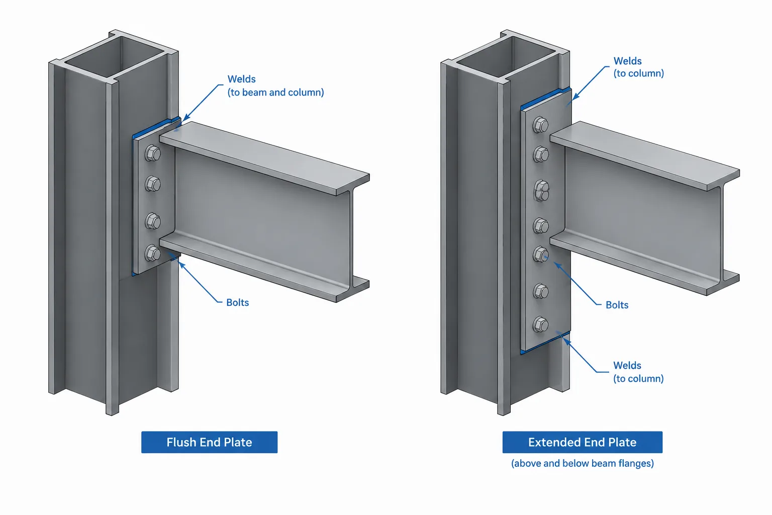
Flush End Plates
A flush end plate generally remains within, or approximately within, the overall depth or profile of the connected member. For a W-shape beam, the top and bottom edges of the plate do not project substantially beyond the beam flanges. The exact relationship between the plate edges and member profile varies with the connection.
This compact outline can be useful where projecting material would conflict with floor systems, adjacent framing, architectural finishes, or erection paths. It does not, however, eliminate the need to check bolt installation space and weld access.
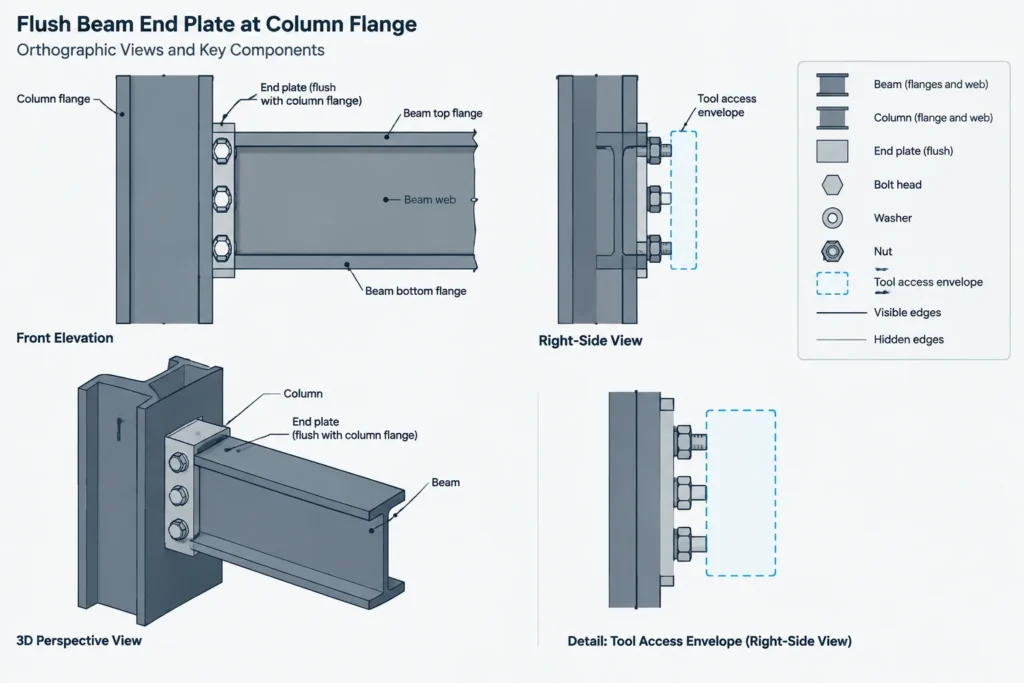
Important flush end-plate geometry
- Plate edge position: The plate outline must be located relative to a clear datum, such as the beam centerline, top of steel, member end, or flange surface.
- Bolt zones: Bolts located between or near beam flanges must have adequate space for holes, washers, nuts, and installation tools.
- Flange interference: A bolt head or nut may fit in a two-dimensional view while still conflicting with a flange, web-to-flange fillet, weld, or adjacent connection component.
- Plate-to-member welds: Weld extents and terminations must be coordinated with member corners, flange edges, and any cope or access feature.
- Supporting surface: The plate must seat against the intended face without interference from projections, welds, or irregular geometry.
Because the plate is compact, its bolt layout may be constrained by the connected member’s flanges and web. A simplified elevation should therefore be checked against sections or a three-dimensional model.
Extended End Plates
An extended end plate projects beyond at least one boundary of the connected member. On a beam connection, the plate may extend above the top flange, below the bottom flange, or in both directions. These extensions create bolt zones outside the member depth and change the connection envelope.
Projection beyond the beam does not by itself define the structural behavior. The bolt pattern, plate bending behavior, welds, and supporting-member response must still be engineered. Drafters should avoid assuming that every extended plate is interchangeable with a standard moment-connection detail.
Important extended end-plate geometry
- Projection direction: Drawings should clearly show whether the plate extends above, below, or on both sides of the connected member.
- External bolt rows: Bolts outside the member depth need coordinated edge distances, spacing, tool access, and clearance from other framing.
- Connection envelope: The projected plate can interfere with slabs, deck, joists, wall systems, stiffeners, splice plates, or perpendicular members.
- Plate flexibility and reinforcement: Plate projection and bolt location affect structural behavior. These are engineering issues, not drafting preferences.
- Erection path: The larger plate may affect how the member is lifted, rotated, inserted, and temporarily supported.
Flush vs. Extended End-Plate Connections at a Glance
| Detailing issue | Flush end plate | Extended end plate |
|---|---|---|
| Plate outline | Generally contained within the connected-member profile | Projects beyond one or more member boundaries |
| Bolt location | Often constrained by flanges, webs, and interior clear space | Can include bolt rows outside the connected-member depth |
| Connection envelope | More compact, but internal congestion may be significant | Larger external envelope requiring broader clash checks |
| Typical drafting risk | Hidden interference near flanges, fillets, and welds | Missed conflicts with deck, slabs, framing, or finishes |
| Erection concern | Access within a compact bolt zone | Insertion and rotation of a projecting plate |
| Structural interpretation | Cannot be determined from the plate outline alone | Cannot be determined from projection alone |
Establish the Controlling Datums
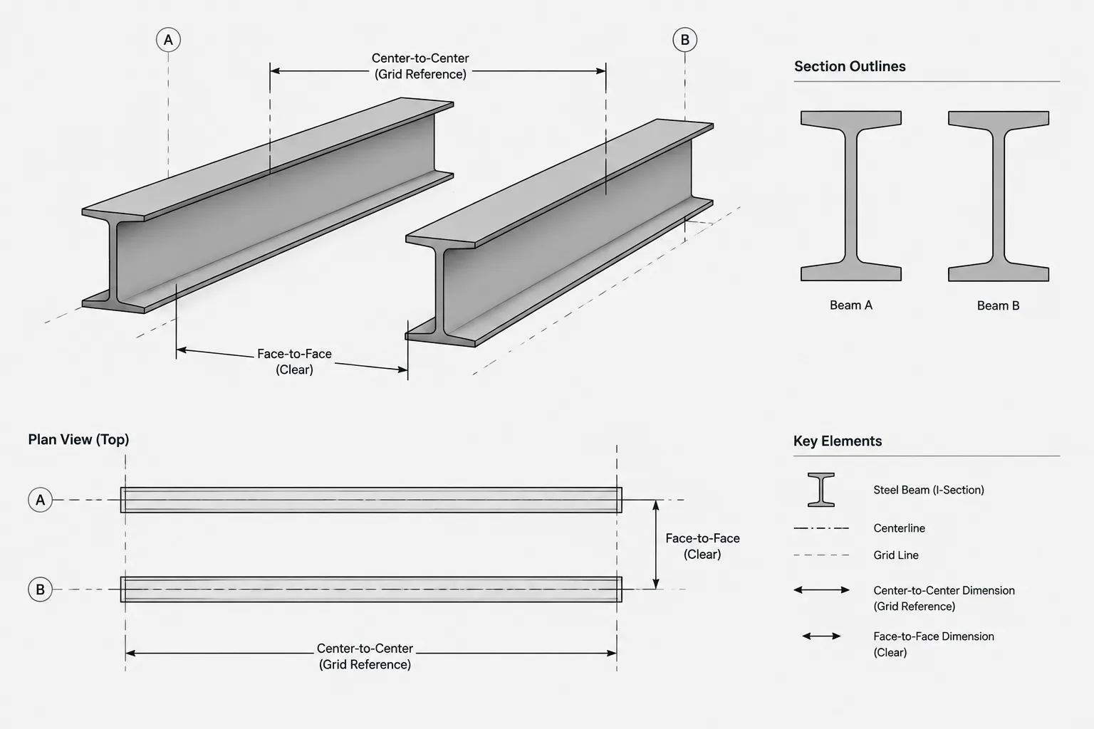
A reliable detail starts with known references. Do not locate the plate and bolts by visually centering them in a CAD view. Relevant datums may include the beam work line, column centerline, face of support, top of steel, beam end, plate face, and bolt-group centerline.
The member length also requires careful interpretation. A beam work-point length is not necessarily its physical cut length. The plate thickness, erection clearance, support face, and any specified setback influence the modeled assembly. Clearly separate dimensions that control member placement from dimensions that control plate fabrication.
When a sloped or skewed beam frames into a support, identify whether dimensions are measured in the member’s local plane, in a true connection-face view, or as plan and elevation projections. A plate that looks rectangular in one view may require a different end cut or spatial orientation than a square framing condition.
Bolt and Tool-Clearance Checks
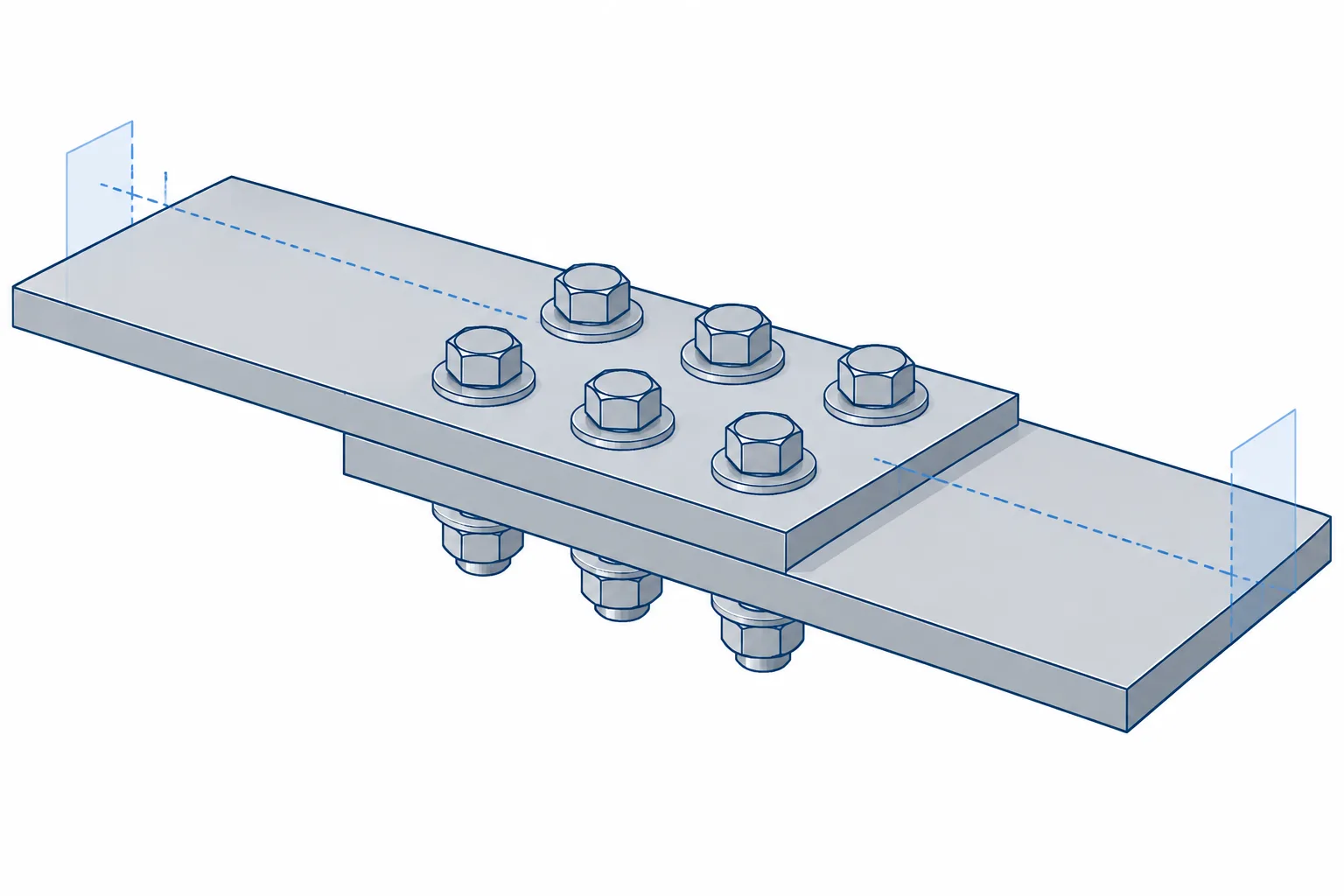
Hole centers are only part of an end-plate layout. The installed fastener assembly occupies three-dimensional space on both sides of the connection. A useful model or drawing check should include the bolt head, nut, washers where required, projection beyond the nut, and the space needed for installation and tightening.
For flush plates, pay particular attention to bolts placed near beam flanges. The nominal gap shown in elevation can be reduced by flange thickness, rolled fillets, weld size, plate distortion, or the orientation of the fastener. For extended plates, check external rows against deck edges, slab zones, column stiffeners, adjacent beams, and architectural elements.
Also verify which side receives the bolt head and which receives the nut if that orientation matters for access or coordination. Drawings should not leave a critical installation assumption hidden in a generic symbol.
Weld and Member-End Coordination
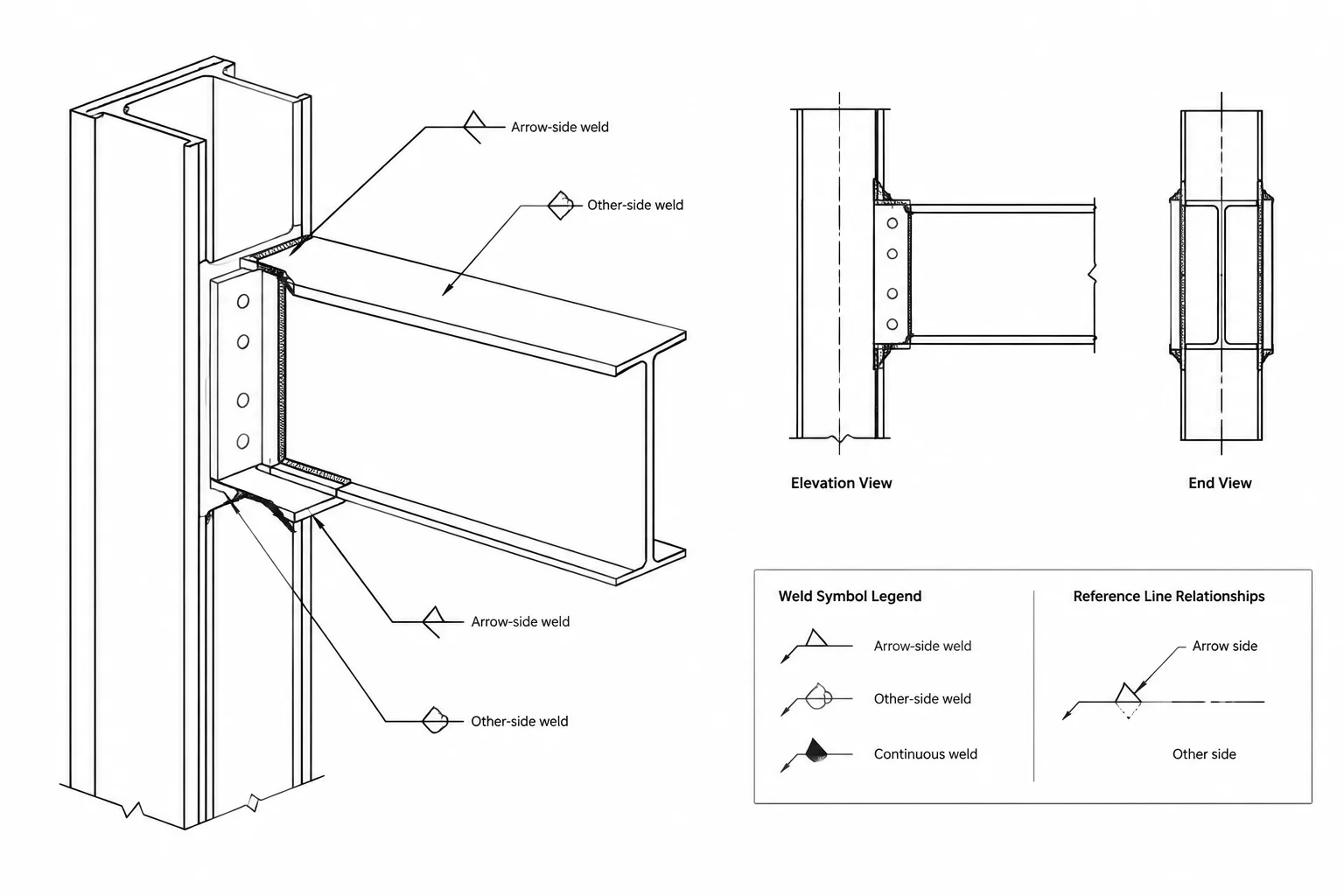
The end plate and connected member are normally fabricated as an assembly, so the member end must match the intended plate fit. The detail should communicate whether the member has a square end, skewed end, sloped cut, cope, corner relief, or another prepared condition.
Weld information must be coordinated across all views. Confirm which member elements are welded to the plate, where welds begin and terminate, and whether the geometry provides access to make and inspect them. A weld line should not pass ambiguously through a rolled fillet or end at a congested plate corner without clarification.
For HSS members, the plate may close the member end or interact with slots, internal plates, venting provisions, or drainage requirements. These conditions deserve explicit sections rather than reliance on a generic end view.
Supporting-Member Checks
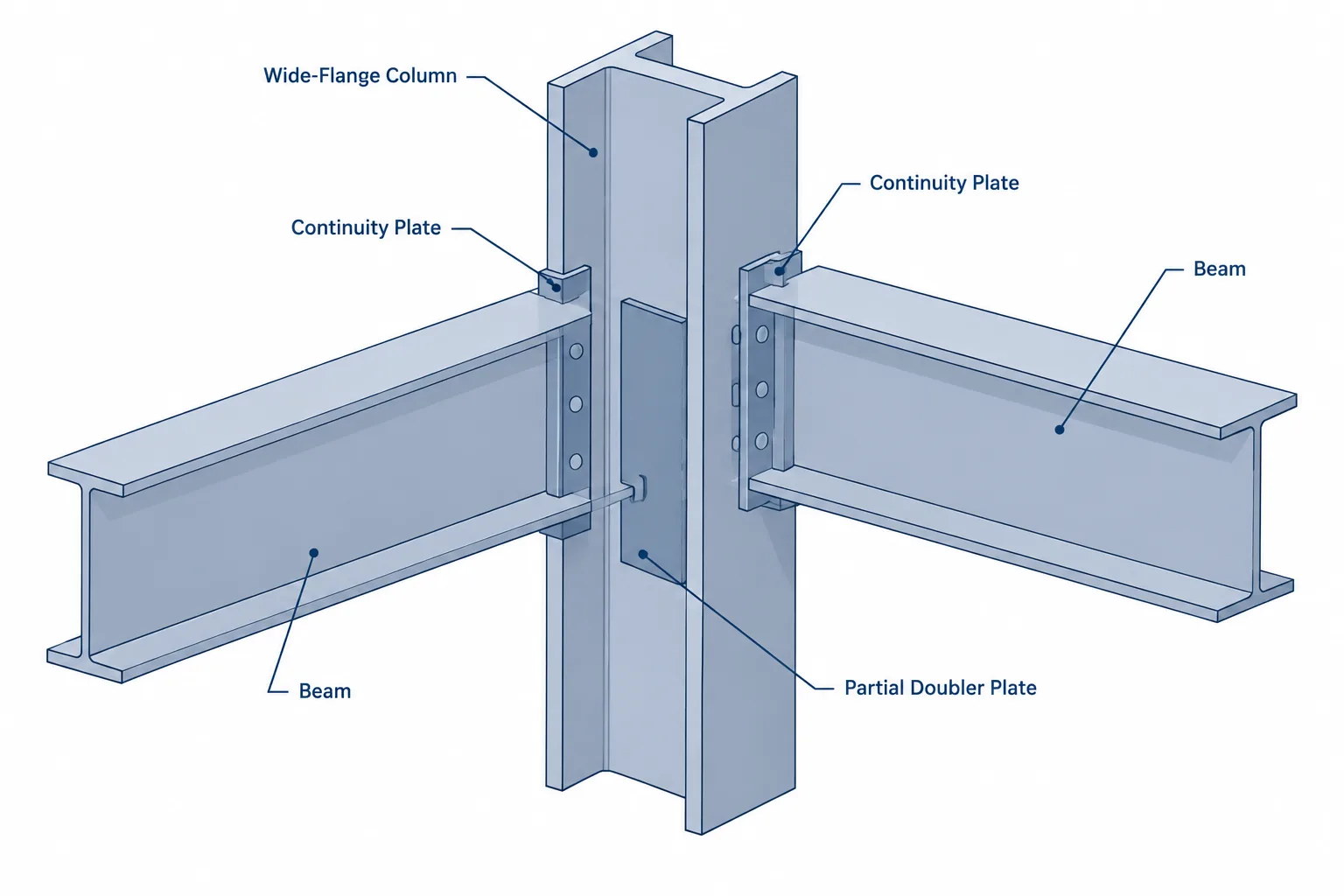
The connection cannot be detailed in isolation from its support. A beam end plate attached to a column flange may interact with column flange width, web location, flange continuity, nearby splices, stiffeners, or other framing. A connection to a column web introduces different clearances and may place bolts near column flanges.
Before releasing drawings, compare the connection model with the actual supporting shape and orientation. Confirm that the bolt group lands on the intended surface, holes avoid incompatible features, and the plate does not extend into another assembly’s working space. Any required supporting-member reinforcement must be shown consistently on the affected assembly and part drawings.
Recommended CAD and Drawing Workflow
- Place the framing work lines. Establish member centerlines, elevations, slopes, and support faces before drawing connection parts.
- Insert verified member geometry. Use the correct shape orientation and enough geometric detail to evaluate flanges, webs, fillets, and HSS corners.
- Model the physical member end. Distinguish the work-point location from the actual cut surface.
- Place the end plate from a defined face. Control its thickness direction and outside dimensions from documented datums.
- Lay out holes by coordinates or controlled construction geometry. Avoid unconstrained visual placement.
- Add fastener envelopes. Check heads, nuts, washers, projection, and tool approach.
- Coordinate welds and cuts. Review plate edges, member flanges, copes, reliefs, and weld terminations together.
- Run surrounding clash checks. Include the supporting member, deck, slabs, adjacent connections, and erection space.
- Create fabrication views. Show the plate as a part and the complete connection as an assembly, with consistent datums.
- Verify against the connection design. Do not infer missing structural requirements from a similar detail.
Common Detailing Errors
- Calling a connection flush or extended without showing the actual plate limits.
- Centering the bolt group graphically instead of dimensioning it from a controlled datum.
- Checking hole clearance but not the installed fastener and tool envelope.
- Using a simplified W-shape outline that hides a flange or fillet conflict.
- Ignoring an extended plate’s interference with deck, slab, or perpendicular framing.
- Confusing beam work-point length with physical member length.
- Copying a prior connection while overlooking a different support orientation or shape size.
- Showing welds in one view that are inconsistent with the section or model.
- Assuming plate projection proves a particular connection behavior or capacity.
Final Detailing Perspective
The practical difference between flush and extended end-plate connections is more than the plate outline. Flush configurations concentrate bolts, welds, and access requirements within a compact region. Extended configurations create additional bolt zones but enlarge the connection envelope and its potential conflicts.
A dependable detail connects the engineer’s design intent to fabricable parts and an erectable assembly. Establish clear datums, model the real member end, check the complete fastener envelope, coordinate weld access, and review the connection against the actual support and surrounding construction. Those steps are more reliable than selecting a familiar-looking detail and adjusting it by eye.