A dimension between two steel members can describe several different geometric relationships. It may locate their centerlines, measure the open space between their nearest faces, or establish the distance from a grid line to a face of steel. These dimensions are not interchangeable, especially when member sizes, orientations, or connection details change.
Understanding center-to-center versus clear dimensions helps drafters build reliable models, helps engineers communicate design intent, and helps fabricators identify which geometry controls. The distinction is especially important in framing plans, equipment-support layouts, wall interfaces, HSS assemblies, and closely spaced connection zones.
What a Center-to-Center Dimension Controls
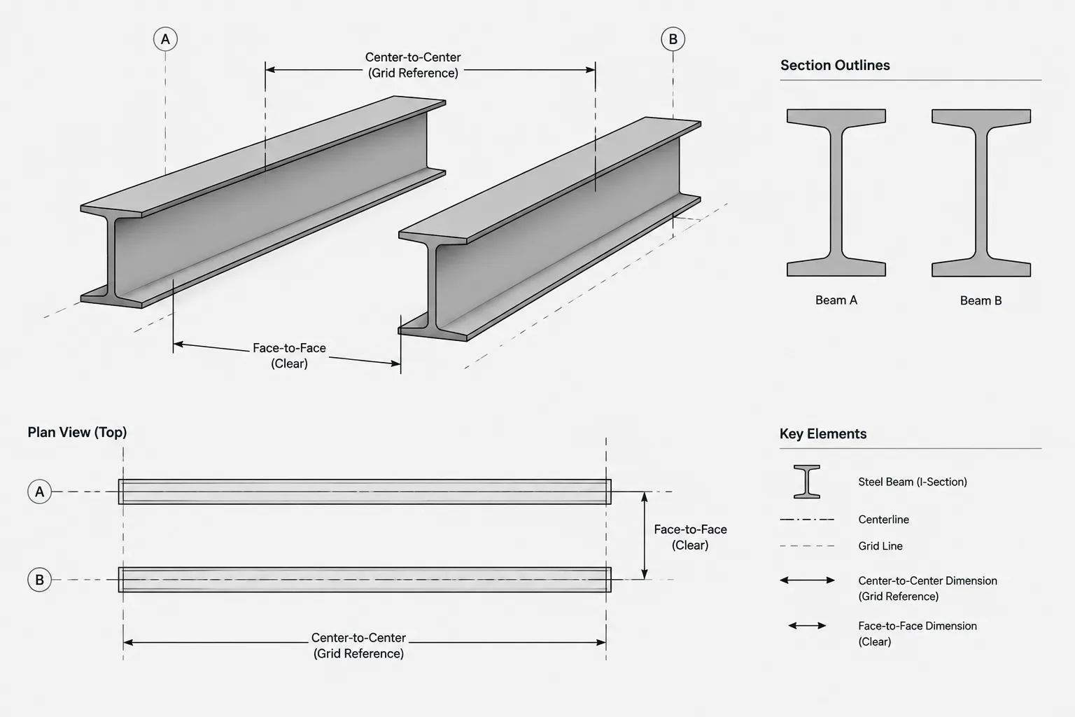
A center-to-center dimension measures between defined centerlines. Depending on the drawing and member type, those lines may represent member work lines, section centroidal axes, geometric centerlines, column grid lines, or another documented layout reference.
Centerline dimensions are useful because they can establish a stable framing layout without depending directly on member width. A beam can often be replaced by another section while its work line remains in the same location. However, the amount of space on either side of that work line may change when the section changes.
Typical uses include:
- Locating columns at grid intersections.
- Spacing parallel beams or joists by work line.
- Defining the plan geometry of a frame.
- Locating braces between connection work points.
- Coordinating analytical members with physical steel models.
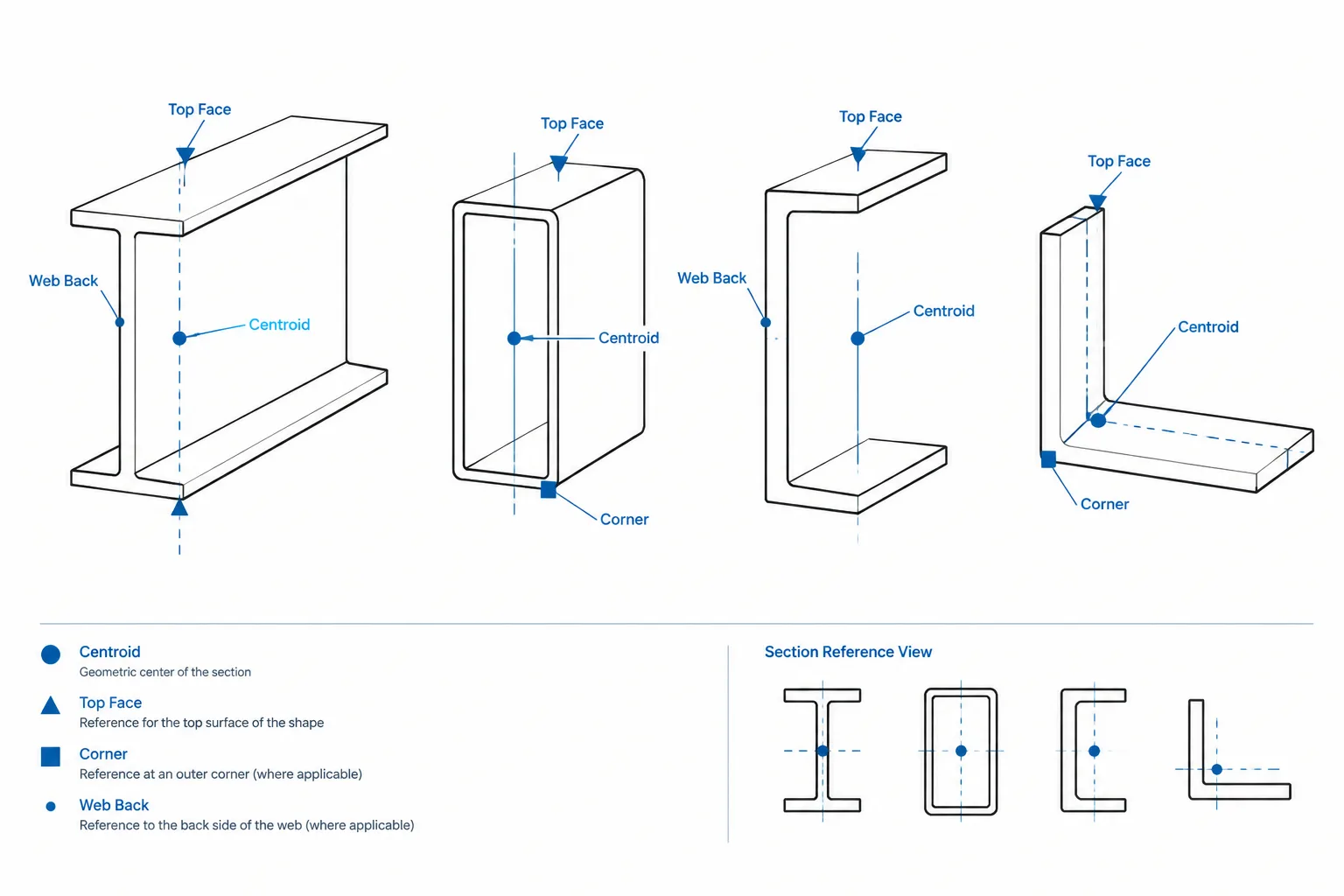
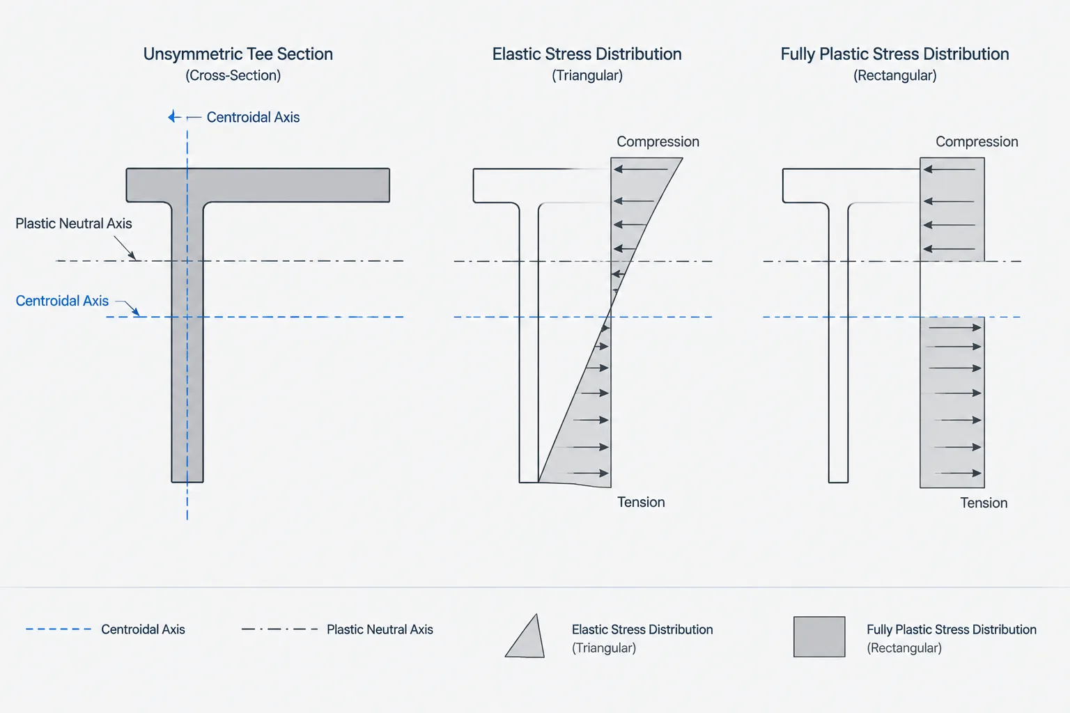
A centerline dimension is only unambiguous when the referenced centerline is clearly defined. The centroidal axis of an unsymmetric angle or channel, for example, may not coincide with the visual center of its bounding box. A connection work line may also differ from the centroidal axis.
What a Clear Dimension Controls
A clear dimension measures unobstructed space between physical boundaries. For two parallel members, it commonly runs from the nearest face of one member to the nearest face of the other. It may also describe clearance between steel and concrete, equipment, piping, cladding, or another trade’s work.
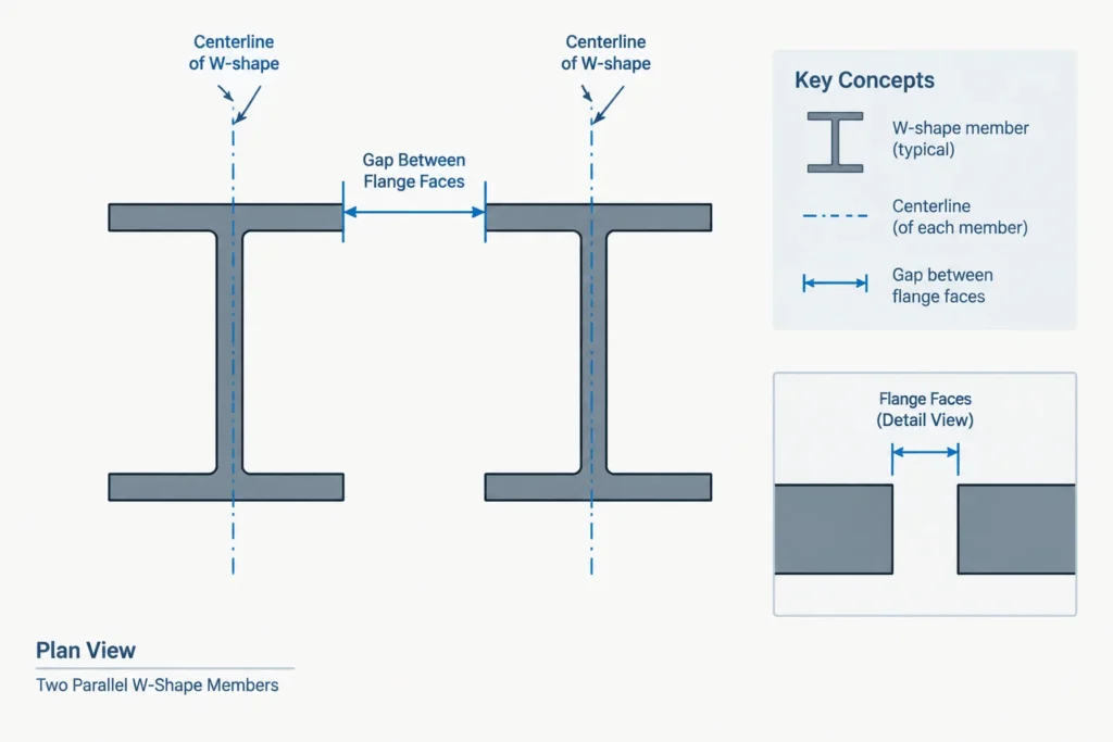
Clear dimensions are appropriate when usable space or physical fit is the primary concern. Examples include:
- An opening that must remain available for equipment or access.
- A gap between HSS members or plate edges.
- Space required between a beam flange and adjacent construction.
- Clear width between column faces.
- Room for bolts, weld access, tools, or erection movement.
Unlike a centerline dimension, a clear dimension depends on the actual extents of the objects. Changing a member depth, flange width, wall orientation, plate projection, or connection component may reduce or increase the available opening even if the framing centerlines remain fixed.
Centerline, Face-of-Steel, and Edge References
Structural drawings commonly combine several reference types. Each should be identified rather than inferred from graphic proximity.
| Reference | What it locates | Common coordination concern |
|---|---|---|
| Grid line | Building or framing layout datum | A member may be centered on, offset from, or unrelated to the grid |
| Member work line | Idealized framing or analytical line | It may not coincide with every physical section center |
| Section centerline | Defined center or centroidal reference of a cross-section | Unsymmetric shapes require careful axis identification |
| Face of steel | Physical outer surface of a member | Its location changes when section dimensions or orientation change |
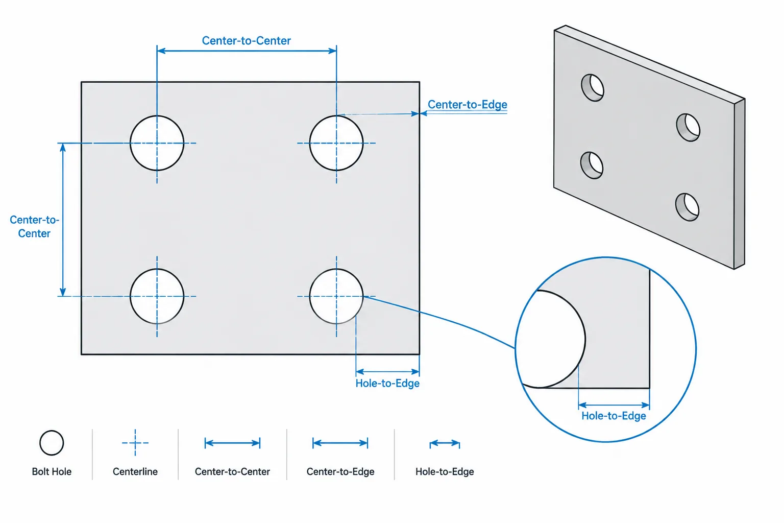
| Plate edge | Cut boundary of a plate or connection element | Projection beyond the supported member can govern clearance |
| Clear opening | Available space between the nearest obstructions | Connection parts may intrude beyond the main member envelope |
Converting Between Center-to-Center and Clear Spacing
For simple parallel, symmetric members, clear spacing can often be understood as the center-to-center spacing minus the distance from each member centerline to its facing surface. If both members have the same width and are centered symmetrically, the relationship is straightforward.
Real steel layouts are often less simple. A conversion must account for the actual orientation and reference point of each section. Potential complications include:
- Different flange widths on adjacent W-shapes.
- Channels with both open sides facing the same direction.
- Angles located by a leg back, heel, centroid, or work line.
- Rectangular HSS rotated so different outside dimensions face the opening.
- Columns offset from their grid lines.
- Skewed members whose projected spacing differs from the shortest true clearance.
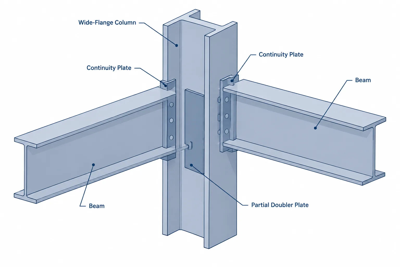
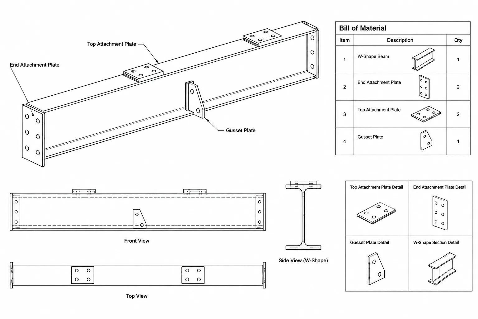
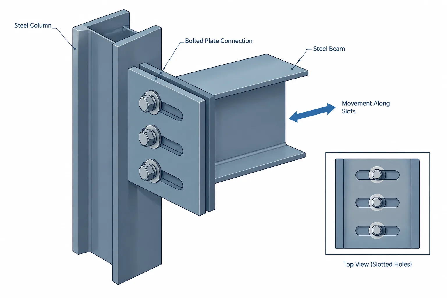
- Connection plates, bolt heads, stiffeners, or welds extending into the nominal opening.
For these cases, do not subtract a generic member width from the centerline spacing. Determine the actual perpendicular distance from each controlling reference line to the relevant physical boundary.
Why Member Substitutions Can Change Clearances
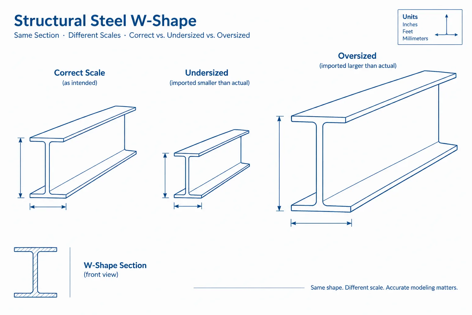
A member substitution can preserve the work-line layout while changing the physical envelope. A revised W-shape may have a different flange width or depth. A rectangular HSS may be rotated. A channel may be reversed. An angle may switch from long-leg vertical to short-leg vertical.
If the original layout was controlled only by center-to-center dimensions, these changes can affect:
- Clear aisle or opening width.
- Distance to walls, deck edges, or equipment.
- Access for bolting and welding.
- Cladding support geometry.
- Clearance between adjacent connection plates.
- Fit of grating, panels, or secondary framing.
This is why a shape change should trigger both a section-property review and a geometric clearance review. Structural adequacy alone does not confirm that the revised member fits the coordinated space.
Skewed Members and True Clear Distance
Clearance becomes more difficult to read when members are skewed in plan. A horizontal or vertical dimension between objects may be only a projected distance, not the shortest distance between their surfaces.
For two parallel skewed members, the most useful clear spacing is often measured perpendicular to their longitudinal direction. For nonparallel members, the minimum clearance may occur at a corner, connection plate, or member end rather than at the dimensioned section.
In CAD, a quick projected measurement can therefore be misleading. Use geometry that represents the actual member extents and inspect the region where the objects come closest. In three-dimensional models, also check whether elevation differences create clearance that is not apparent in plan—or produce a clash hidden by the plan view.
Do Connection Components Control the Opening?
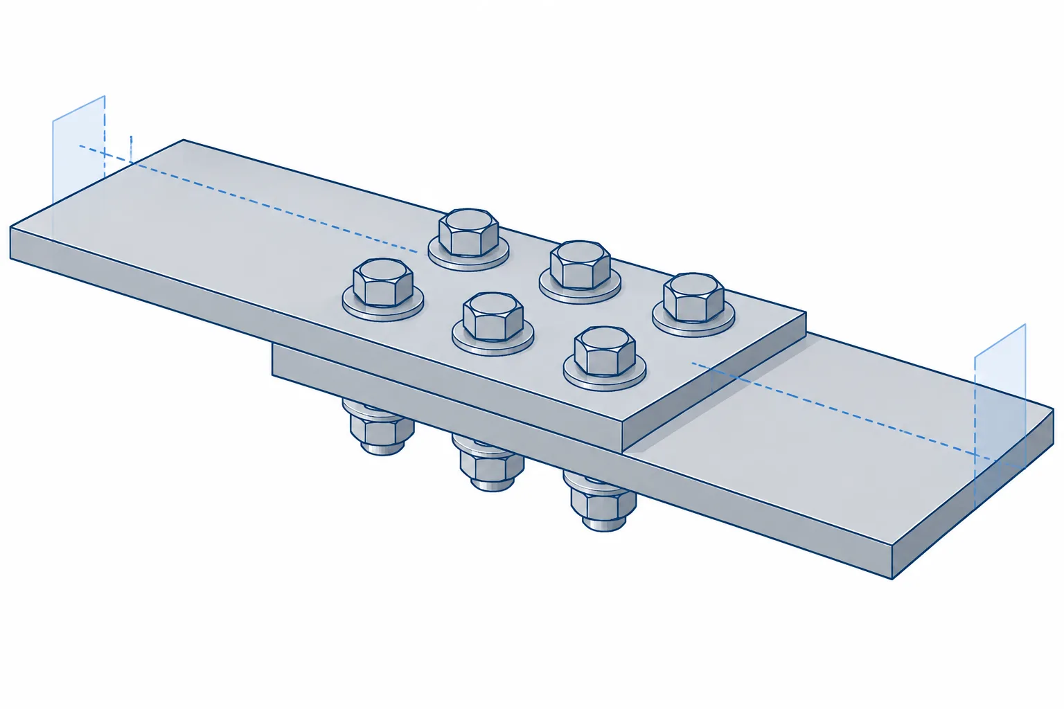
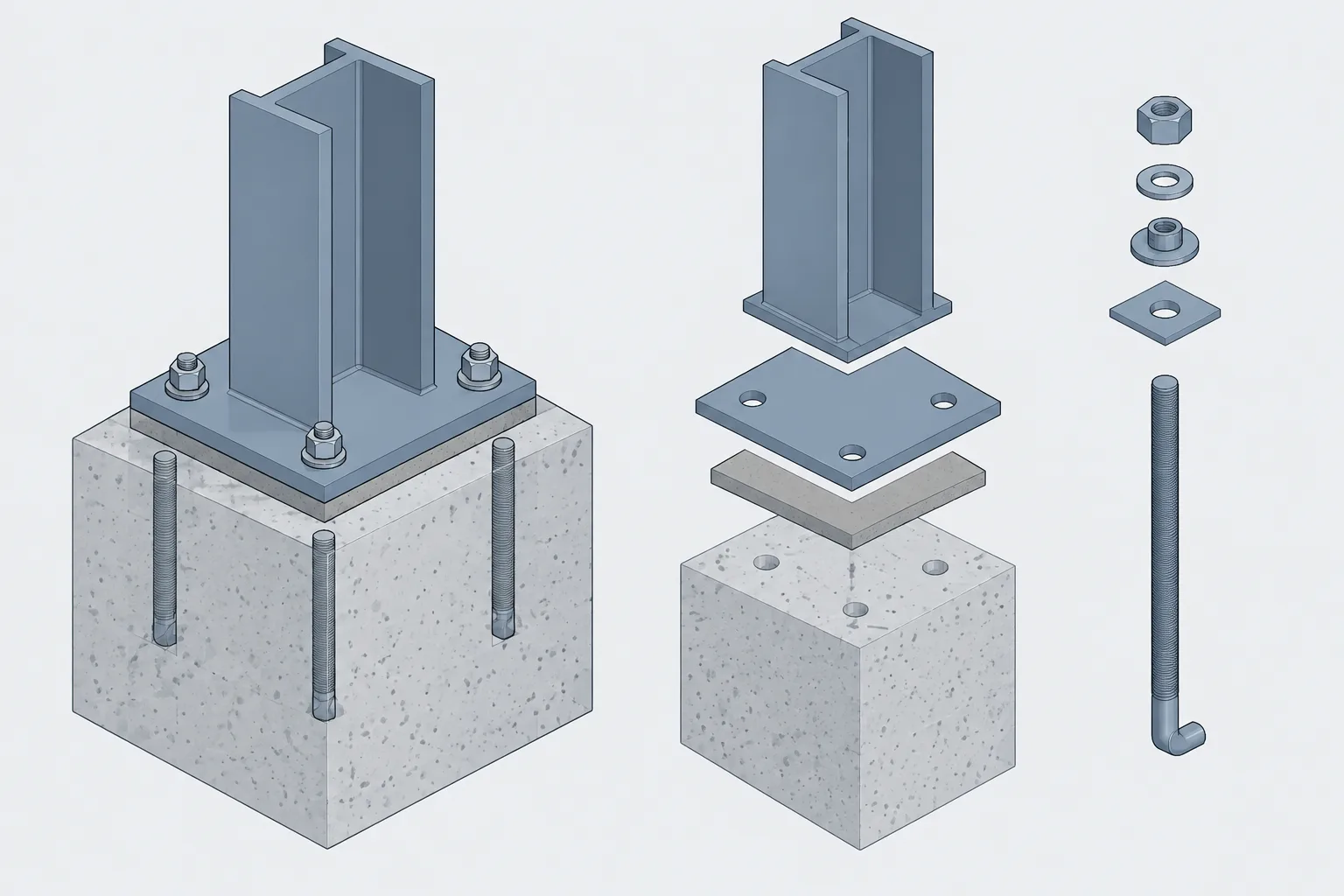
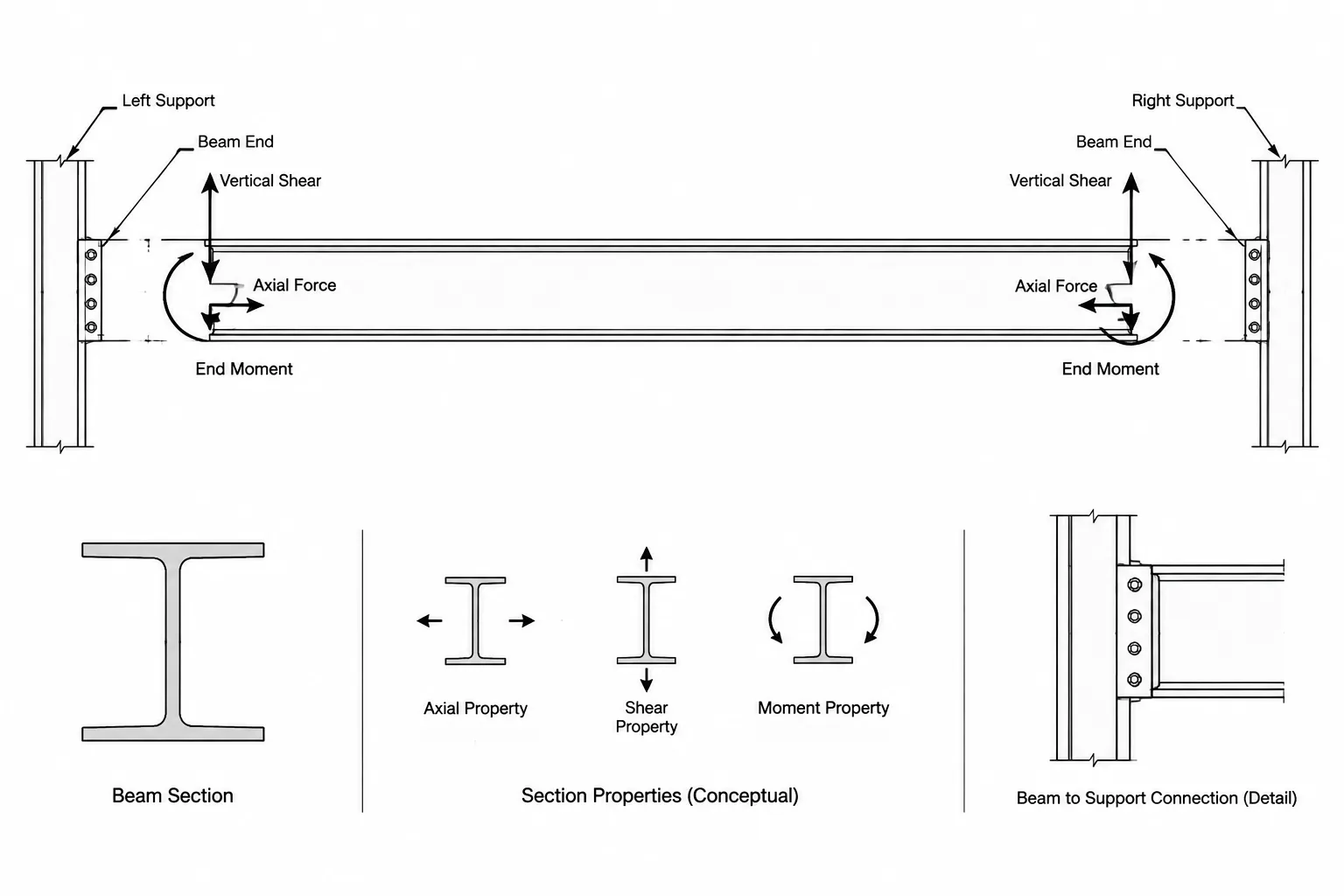
The main member faces do not always define the true clear opening. A shear plate, clip angle, gusset, stiffener, splice plate, bolt assembly, weld profile, or erection aid may extend farther into the space.
It is helpful to distinguish between:
- Member clear distance: space between the primary steel section surfaces.
- Assembly clear distance: space between the nearest parts of the completed steel assemblies.
- Operational clearance: space available after considering installation access, movement, finishes, and adjacent systems.
A drawing note that says only “clear” can be interpreted differently if it does not identify the controlling objects. Dimensions should point to the relevant faces or be accompanied by wording that defines the intended opening.
CAD and BIM Workflow
Establish the controlling datum first
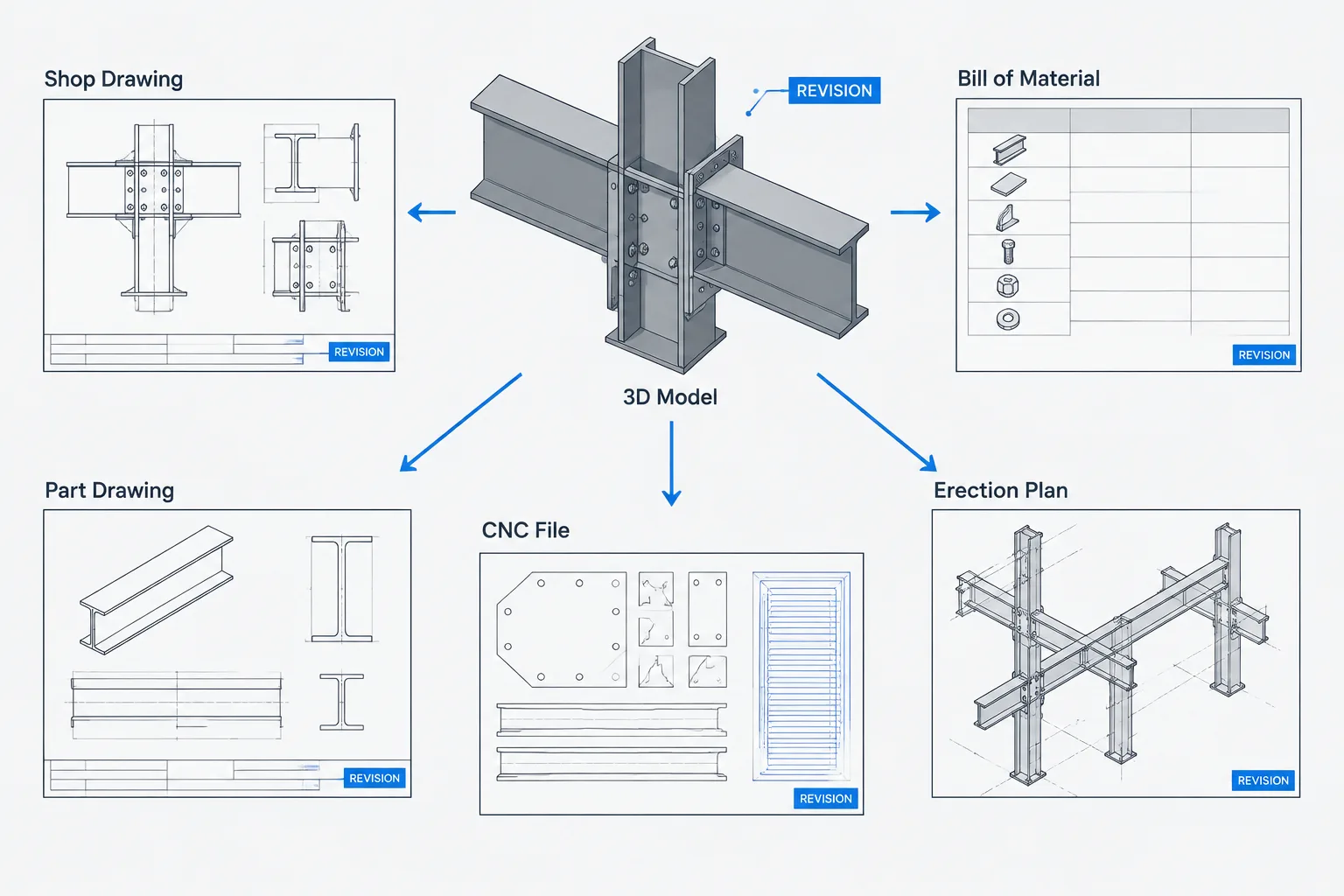
Before placing members, identify whether the layout is controlled by grids, work lines, faces of steel, or a required clear opening. Avoid placing members by eye and adding dimensions afterward. The model should be constructed from the same references shown as controlling on the drawings.
Model physical extents where fit matters
Single-line members may be adequate for early framing layout, but they cannot confirm face-to-face clearance. Use section envelopes or detailed geometry when checking interfaces, connection congestion, and openings.
Keep derived dimensions identifiable
If a clear distance is derived from centerlines and section dimensions, treat it as a result rather than an independent controlling input unless the design intent says otherwise. Overconstraining both values can create conflicts when a shape changes.
Check offsets and rotations
Verify section insertion points, local axes, offsets, and rotations before trusting a measured gap. A correctly named shape placed from the wrong insertion point can produce an incorrect face location even when its section geometry is accurate.
Drawing Practices That Reduce Ambiguity
- Label grid, member, and work-line references consistently.
- Use dimension extension lines that visibly terminate at the intended faces or centerlines.
- Add centerline symbols where the reference might otherwise be mistaken for an edge.
- State whether a required opening is clear between members or between complete assemblies.
- Show offsets when a member is not centered on its grid or work line.
- Dimension unsymmetric shapes from a practical, identifiable surface when appropriate.
- Recheck clear openings after member-size, orientation, or connection revisions.
- Avoid relying on scaled measurements from plotted drawings.
A Practical Coordination Check
When reviewing a structural steel layout, ask four questions: What datum locates each member? What physical surfaces define the opening? Are connection components included in the clearance check? What happens if the member size or orientation changes?
Center-to-center dimensions are effective for establishing structural layout, while clear dimensions communicate physical space. Reliable drawings and models use each for its proper purpose and make the controlling reference explicit. When both framing location and usable clearance matter, show enough information to verify both without forcing the fabricator or field crew to guess.