Hot-dip galvanizing hollow structural sections requires more coordination than simply adding a coating note to the drawings. An HSS member may appear open in the model while becoming partially or completely sealed after cap plates, end plates, base plates, diaphragms, or connection plates are installed. If air, moisture, pretreatment solutions, and molten zinc cannot move through the assembly as intended, the result can be a processing hazard, incomplete coating, trapped material, poor drainage, or unwanted surface buildup.
Vent and drain holes are therefore part of the fabrication and galvanizing plan. Their locations depend on the member geometry, assembly sequence, dipping orientation, internal obstructions, and the galvanizer’s handling method. They should not be placed from a generic CAD detail without project-specific review.
Why Hollow Steel Needs Venting and Drainage
During hot-dip galvanizing, a fabricated steel assembly moves through cleaning and preparation stages before immersion in molten zinc. A hollow member needs suitable paths for liquids to enter and leave while displaced air escapes. After immersion, excess zinc must also be able to drain from cavities and corners.
A completely sealed cavity is especially important to identify. Heat can expand trapped air, and hidden moisture can create a serious hazard. The galvanizer must know where enclosed spaces exist, including small cavities formed by reinforcement plates, end closures, overlapping parts, or intermittent weld layouts.
The terms vent and drain describe functions rather than permanently fixed directions on the finished structure:
- Vent openings allow air and process gases to escape as liquids enter a cavity.
- Drain openings allow preparation liquids and molten zinc to leave the cavity.
- Combination openings may perform different functions as the assembly is immersed, rotated, or withdrawn.
The required flow path is based on the member’s orientation during galvanizing, not merely its final installed orientation.
Finished Orientation Is Not Dipping Orientation
A common detailing mistake is to place a hole at what appears to be the top or bottom of an erected member without considering how the galvanizer will handle it. A sloped HSS brace, for example, may be dipped at a different angle from its final slope. A column assembly may enter the bath diagonally rather than vertically. Long assemblies may also be rotated to clear equipment or improve drainage.
This distinction changes which corners become high points and low points during processing. Air collects at process high points, while liquids and zinc collect at process low points. An opening located near the bottom of the erected member may not drain the member during withdrawal if the assembly is suspended from the opposite end.
Drawings should therefore avoid unsupported assumptions about dipping direction. When hole placement is sensitive to orientation, the fabricator and galvanizer should coordinate lifting points, immersion direction, withdrawal direction, and permitted hole locations before fabrication is finalized.
Internal Plates Can Interrupt the Flow Path
An HSS can look continuous externally while being divided into separate enclosed chambers internally. Internal diaphragms, splice plates, knife plates, reinforcement plates, and concealed end closures may block air and liquid movement.
Each isolated chamber must be considered on its own. A vent at one end of the member does not serve a cavity separated by a solid internal plate. Likewise, a small gap shown schematically around an internal component may not provide a reliable process path after welding, distortion, or zinc buildup.
When reviewing an HSS assembly, trace the internal path rather than reviewing only the exterior:
- Identify every plate that crosses all or part of the hollow section.
- Determine whether welds create sealed pockets between intersecting parts.
- Check whether slots or openings remain connected after final assembly.
- Confirm that process liquids can leave each compartment.
- Consider whether zinc can drain without collecting behind a diaphragm or in a corner.
If an internal opening is proposed, its geometry must be coordinated with structural demands, welding access, fabrication methods, and the galvanizer’s requirements. Removing material from a diaphragm or connection plate is not purely a drafting decision.
Common HSS Conditions Requiring Special Attention
| Assembly condition | Potential issue | Coordination question |
|---|---|---|
| Cap plate welded to an HSS end | The cap may create a sealed cavity or trap zinc near the end. | Will openings be placed in the cap, the HSS wall, or another accessible location? |
| HSS column welded to a base plate | The base plate can close the lower end and restrict drainage. | How will the column be oriented, and can openings remain accessible after welding? |
| Knife plate extending into HSS | The plate and welds may divide the interior or obstruct flow. | Does the plate create separate chambers or narrow drainage paths? |
| Internal diaphragm | A full-depth plate can isolate part of the member. | Does each resulting cavity have a verified vent and drain route? |
| HSS truss or frame assembly | Intersecting members may appear connected but remain internally isolated. | Which members communicate internally, and which require separate openings? |
| Decorative closure or seal-welded detail | Appearance requirements may conflict with visible process holes. | Can hole location and any approved closure method be coordinated before fabrication? |
Hole Location Is a Structural and Fabrication Decision
Vent and drain openings remove steel and may be located near welded connections, highly stressed regions, member ends, or concentrated-force locations. Their effect cannot be dismissed because they are described as process holes. The engineer responsible for the member should review openings that could affect strength, serviceability, fatigue behavior, or connection performance.
Fabrication constraints matter as well. A hole that is theoretically suitable may be difficult to drill, cut, inspect, or clean after an end plate is attached. It may also interfere with a weld, bolt line, backing component, erection aid, architectural cover, fireproofing interface, or drainage path required in service.
The best location often results from balancing several objectives:
- Provide direct flow rather than relying on small incidental gaps.
- Place openings near relevant process high and low points.
- Avoid creating pockets around internal plates and welds.
- Maintain required connection geometry and edge material.
- Keep the opening accessible for fabrication and inspection.
- Address appearance where exposed steel is architecturally important.
Opening size and shape should be confirmed with the galvanizer and project engineer. A copied hole size from an unrelated detail may not suit the enclosed volume, member length, zinc flow, or shop process.
How to Show Vent and Drain Provisions on Drawings
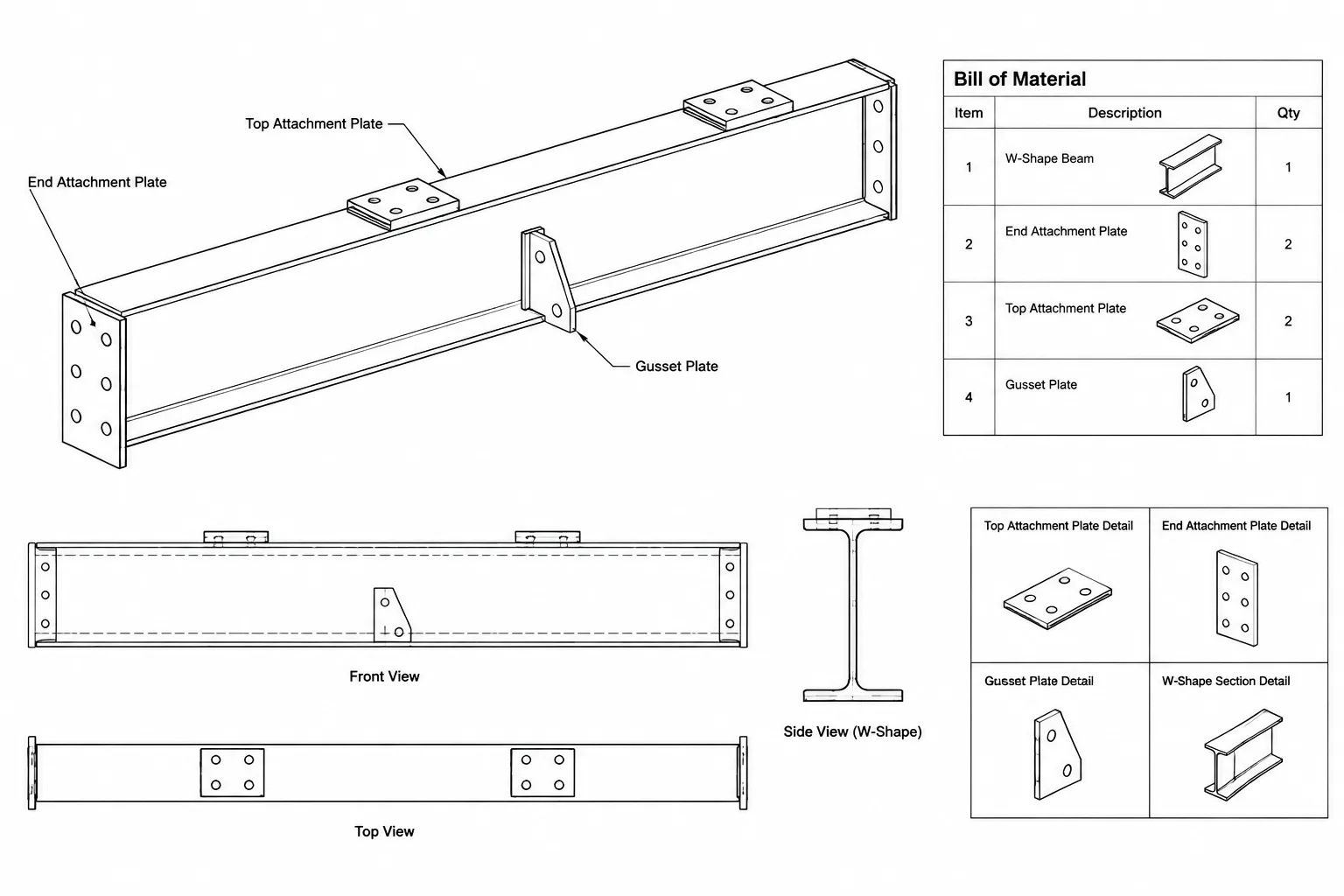
A useful shop drawing identifies more than a circle on one elevation. The opening should be located from stable datums and shown in enough views to remove ambiguity. If a hole passes through only one HSS wall, the drawing should identify the applicable face. If openings occur on opposite walls, a section or end view may be clearer than hidden lines.
Drawing information may include:
- Hole or slot identification and quantity.
- Controlling location dimensions.
- The HSS face receiving the opening.
- Relationship to end plates, cap plates, diaphragms, and welds.
- A section showing internal communication between cavities.
- A process note directing final coordination to the galvanizer.
- Whether an opening remains open, is screened, receives a separate closure, or is treated by another approved method after galvanizing.
Do not use a vague note such as “provide vents as required” as the only communication when the assembly contains hidden compartments. General notes can establish responsibility, but the detailer still needs to expose the relevant geometry so the fabricator and galvanizer can evaluate it.
Modeling and CAD Review Workflow
A three-dimensional model can help find enclosed volumes, but only if the model includes the parts that actually close the HSS. Simplified member objects often omit internal diaphragms, weld effects, temporary shipping plates, and small openings. Automated clash detection also does not prove that a cavity can vent or drain.
A practical review can follow this sequence:
- Start with the final fabricated assembly. Include closures, connection plates, internal parts, and weld-related boundaries.
- Divide the assembly into cavities. Treat each fully separated volume as an independent space.
- Assign a likely process orientation. Obtain galvanizer input rather than relying solely on erection orientation.
- Trace entry, venting, and drainage. Look for high-point air pockets and low-point liquid traps.
- Review structural effects. Submit proposed openings for engineering acceptance where required.
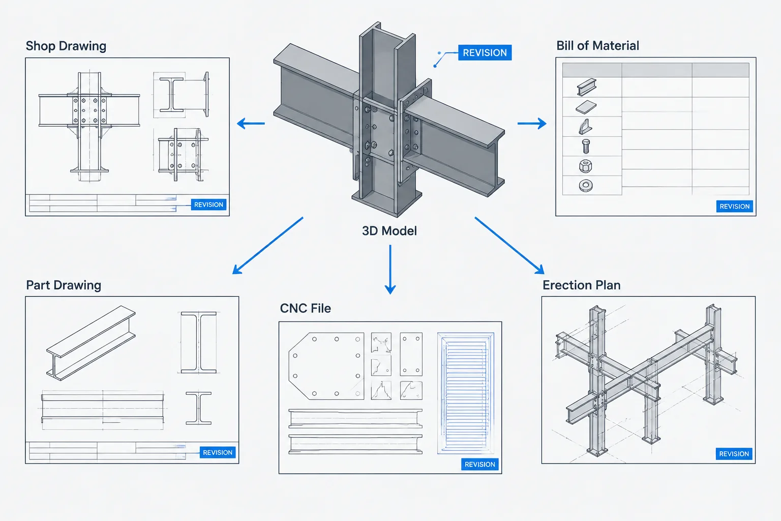
- Document the result. Show openings in the views, part details, and bill information needed for fabrication.
- Recheck revisions. A moved diaphragm, added cap, or changed connection can invalidate the original venting plan.
Do Not Confuse Process Drainage with In-Service Drainage
Galvanizing openings and in-service weep holes are related but not interchangeable concepts. A hole that drains zinc during fabrication may not be at the low point after erection. Conversely, a rainwater drainage hole in the finished structure may be poorly positioned for the dipping process.
If the HSS can admit water during service, the project team should separately evaluate drainage, corrosion exposure, insect or debris entry, sealants, closures, and maintenance access. The drawings should make clear which openings are required for galvanizing and which are intended to remain functional after erection.
Final Coordination Checklist
- Has every sealed or potentially sealed HSS cavity been identified?
- Are internal diaphragms and inserted plates shown in the review model or sections?
- Has the anticipated immersion and withdrawal orientation been discussed?
- Does each cavity have a credible path for air, liquids, and zinc?
- Have opening locations been checked against welds, bolts, and connection forces?
- Are exposed openings coordinated with architectural expectations?
- Are process holes distinguished from permanent service drainage?
- Will a later fabrication revision create a new closed pocket?
- Have the galvanizer, fabricator, detailer, and engineer resolved their respective decisions?
Vent and drain detailing is most reliable when it is treated as assembly coordination rather than a last-minute shop modification. By tracing internal cavities, separating dipping orientation from erection orientation, and documenting verified flow paths, the project team can reduce fabrication surprises while preserving the structural and visual intent of the HSS assembly.