A bolted lap joint connects steel parts by placing one component over another and fastening through the overlapping region. The concept is simple, but the resulting geometry affects the load path, bolt grip, fit-up, access, material takeoff, and clarity of the shop drawings.
Lap joints appear in plates, flat bars, splice components, angles, cold-formed elements, and miscellaneous framing. They may be permanent structural connections or part of an erection and alignment strategy. In every case, the detailer must represent the actual stack of steel rather than treating the joint as a flat diagram of bolt centers.
This guide focuses on geometric and drafting coordination. Connection strength, bolt selection, hole type, surface preparation, and required overlap must be established by the responsible design and project documents.
What Defines a Steel Lap Joint?
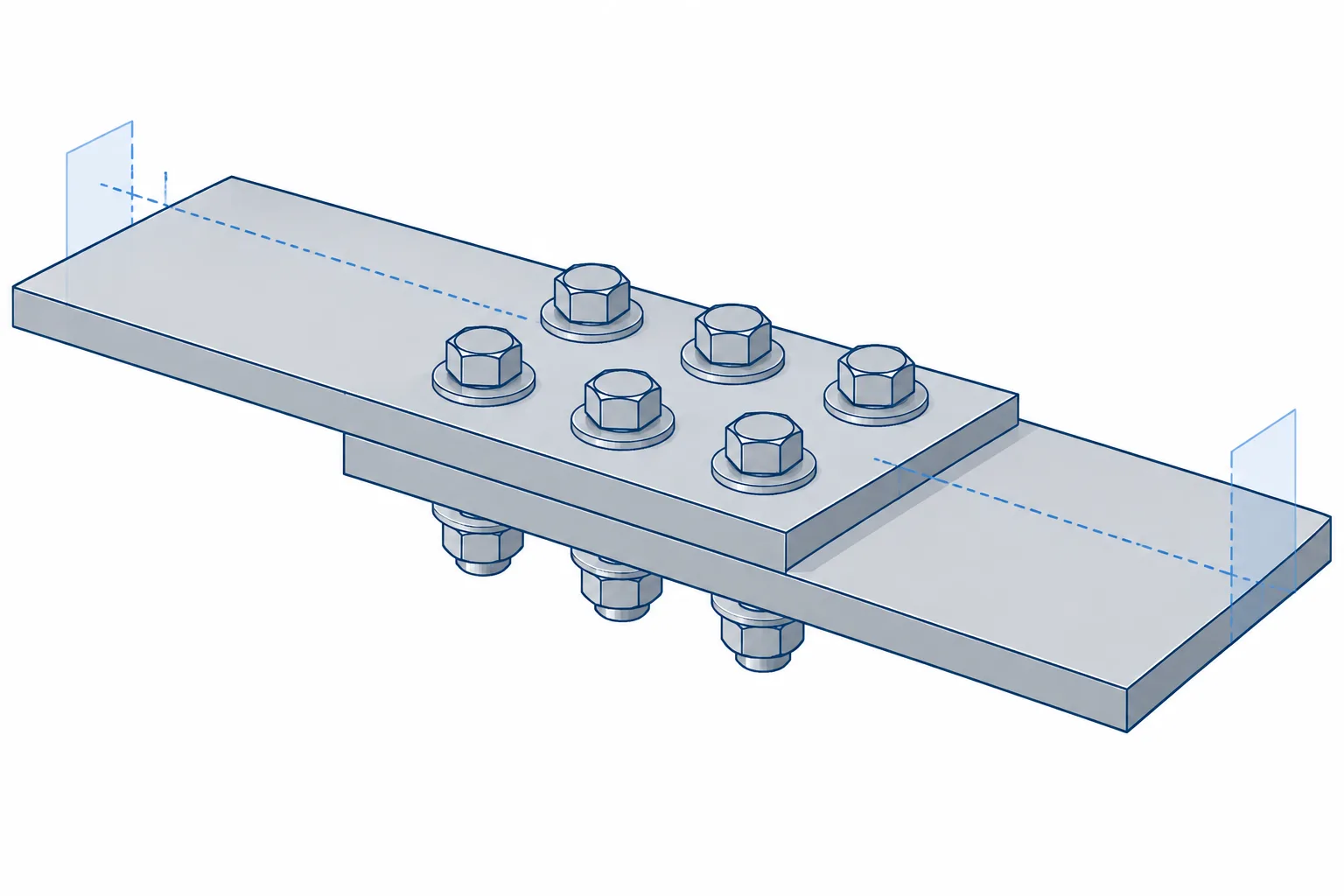
A lap joint has an overlap zone in which connected parts occupy different planes. A simple joint may contain two plates, while a more complex assembly can include splice plates, fillers, connection angles, washers, or other components.
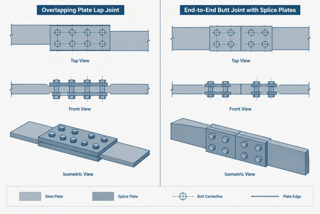
This distinguishes it from a butt joint, where the primary parts terminate near one another and separate splice material bridges the interface. The distinction matters because a lap joint can shift the centerline of one part relative to another and create an eccentric load path.
| Joint feature | Lap joint | Butt joint with splice material |
|---|---|---|
| Primary-part position | Parts overlap | Parts generally meet end to end |
| Part planes | Usually offset by the ply thickness | Primary parts may remain in a common plane |
| Connection region | Located within the overlap | Spans the interface between member ends |
| Typical detailing concern | Offset, eccentricity, and overlap length | End gap, splice alignment, and splice-plate layout |
Start with the Ply Stack-Up
The ply stack-up is the ordered set of materials through which a bolt passes. A reliable lap-joint detail identifies each ply and its thickness before bolt length or projection is considered.
A stack-up check should account for:
- The main connected steel parts.
- Splice plates, connection angles, or reinforcing material.
- Fillers or shims that form part of the final assembly.
- Washer locations and any project-specific washer arrangement.
- The selected bolt assembly and required installation access.
- Coatings or surface conditions that affect fit-up, where relevant to the project.
Do not infer the bolt grip from a plan view alone. Two plates can appear coincident in plan while occupying separate elevations. A section through the bolt group is often the clearest way to show the actual stack.
Overlap Length Is More Than a Bolt-Pattern Dimension
The overlap must accommodate the designed fastener pattern as well as the material extending beyond it. Its geometry is therefore related to bolt rows, end distances, edge distances, fabrication tolerances, and the physical ends of the connected parts.
On a shop drawing, avoid defining the overlap indirectly through several unrelated dimensions when a controlling dimension can be shown clearly. Depending on the assembly, useful controls may include:
- Part end to part end.
- Part end to the first bolt line.
- Work point or member datum to the joint interface.
- Bolt-line spacing within the connection.
- Overall assembled length.
The controlling dimension scheme should match fabrication and inspection needs. Redundant dimensions can be helpful as references, but they should not create competing definitions of the same geometry.
Understand the Offset Load Path
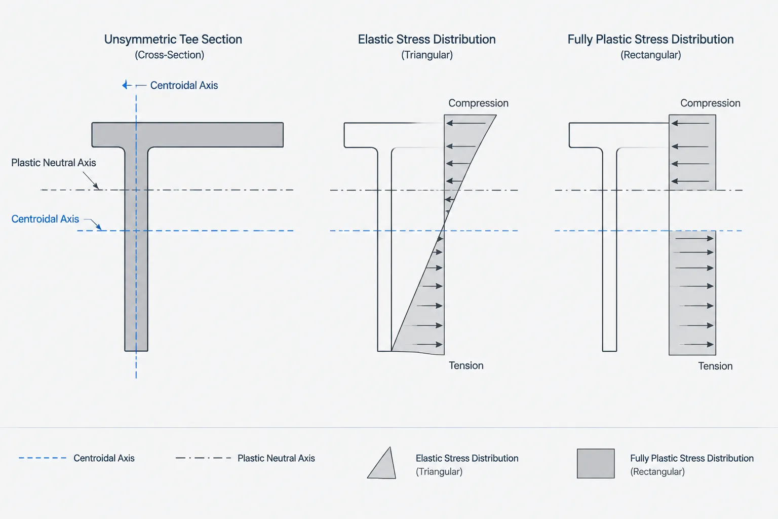
When two plates overlap, their centroids are not normally in the same plane. Force passing from one part to the other may therefore act through an offset. This can introduce local bending or other secondary effects in the connected parts and fasteners.
The detailer should not attempt to resolve that design question by moving bolts or adding material without authorization. However, the drawing and model must preserve the intended geometry so the connection designer is evaluating the same arrangement that will be fabricated.
Potential warning signs include:
- A thin connected element lapped onto a much thicker component.
- Several fillers added to one side of the joint.
- A load line that appears centered in one member but offset in the other.
- A lap joint that changes the member elevation or face alignment.
- A bolt group moved to clear another component without a design review.
If a symmetric load path is intended, a connection using material on both sides may be considered by the designer. That is a different physical assembly and should not be substituted for a single-sided lap detail during drafting.
Hole Alignment Through Multiple Plies
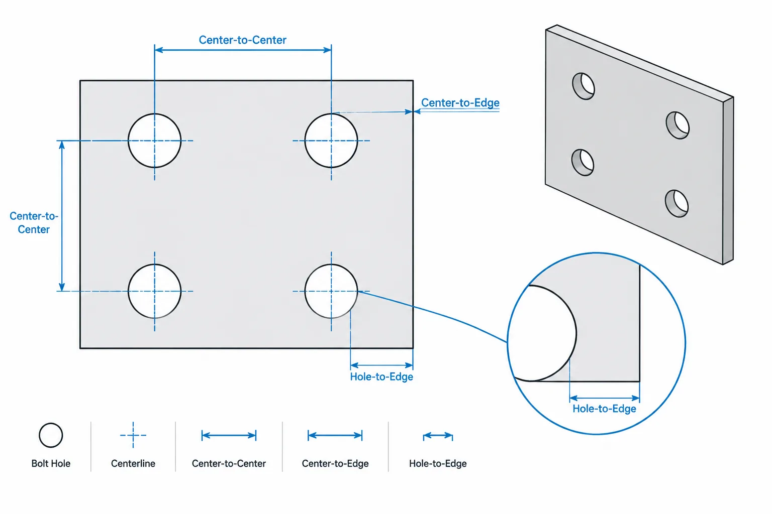
Every bolted ply needs a compatible hole location. In CAD, copying a hole pattern between parts is convenient, but it is safe only when the parts share the correct coordinate system, orientation, and datum.
Check that:
- The hole centers are transferred from a common assembly datum.
- Mirrored parts have not reversed an asymmetric pattern.
- Slots, when specified, retain the intended direction in every affected ply.
- Hole callouts correspond to the correct part rather than only the assembly view.
- Plate rotations in the model have not changed local hole coordinates.
- NC or CNC output matches the approved part geometry.
A useful model check is to place a temporary cylinder or centerline through each bolt location. A continuous axis should pass through all intended plies without stepping sideways or intersecting unintended steel.
Fit-Up, Faying Surfaces, and Unintended Gaps
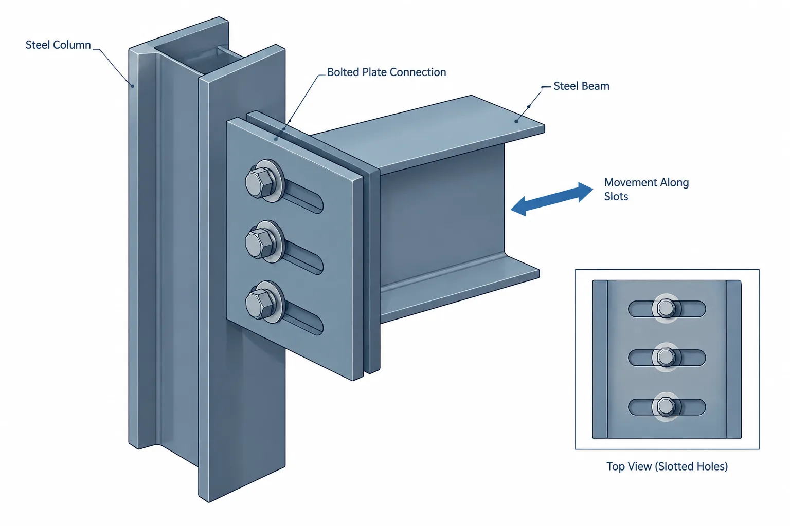
The contacting faces of a bolted lap joint are commonly called faying surfaces. The drawing should make clear which surfaces meet and whether fillers, shims, coatings, or preparation requirements apply.
An unexplained model gap is not a harmless graphics issue. It may alter bolt grip, conceal an incorrect offset, or suggest that a filler is missing. Conversely, forcing all modeled faces into contact can hide a real geometry conflict elsewhere in the assembly.
Surface treatment can also be a design and specification issue, particularly when connection behavior depends on the condition of the contact surfaces. Detailers should carry the specified requirements into notes and fabrication information without inventing or generalizing them.
Bolt Access and Installation Sequence
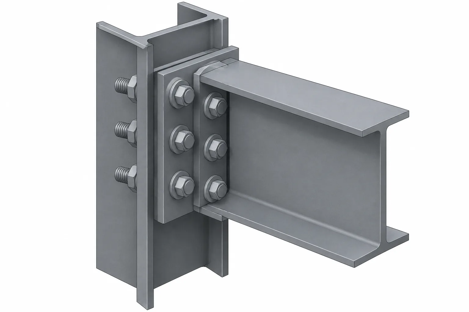
A bolt pattern that fits within the overlap may still be difficult to install. The joint must provide access for inserting bolts, placing washers and nuts, and operating the required installation tools.
Review access in three dimensions, especially when the lap is close to:
- Angle legs or channel flanges.
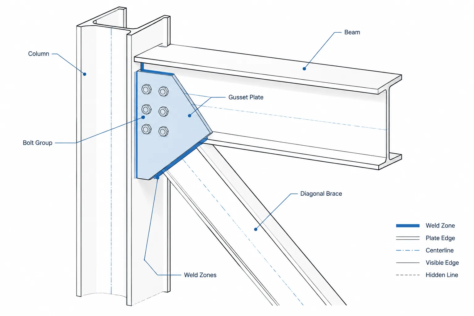
- Stiffeners and gusset plates.
- HSS walls or closed connection zones.
- Adjacent bolt rows.
- Welds, returns, and plate bends.
- Concrete, decking, cladding, or other trades.
The erection sequence matters as well. A bolt may be accessible in an isolated shop model but blocked after another member or plate is installed. Assembly views should be checked in the anticipated order of fabrication and erection.
Bolts and Welds in the Same Lap Region
Some details combine bolts with shop or field welds. Their functions must be understood rather than assumed. A bolt might provide permanent load transfer, temporary positioning, or part of a combined connection concept established by the designer.
Coordinate bolt holes with weld access, weld terminations, and the physical space required for welding and inspection. Avoid casually placing a weld over a hole edge, washer footprint, or bolt installation zone. If the drawing does not make the intended load-transfer mechanism clear, request clarification.
Recommended Drawing Views
A complete lap-joint presentation often needs more than one view:
- Plan or elevation: Shows the bolt pattern, plate outline, and overlap limits.
- Section through the bolts: Shows ply order, thickness changes, washers, fillers, and member offsets.
- End view: Confirms lateral alignment and edge relationships.
- Assembly detail: Relates the joint to work points, member ends, and surrounding steel.
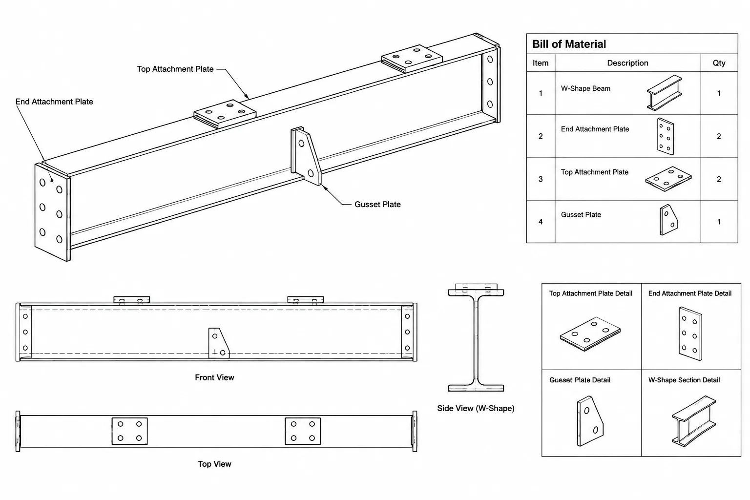
- Part details: Define each plate or component independently for fabrication.
Hidden lines can support interpretation, but they should not replace a section when the ply arrangement is important. The goal is to remove ambiguity for fabrication and checking, not merely to reduce the number of views.
A Practical CAD and Drawing Check
- Identify the connected parts and the intended joint type.
- Confirm the overlap boundaries and controlling datums.
- Model each ply at its actual position rather than as coplanar linework.
- Verify the bolt axis through every connected component.
- Review grip, washer placement, and tool access using the specified assembly.
- Check edge and end relationships against the connection design information.
- Examine eccentricity and offsets for consistency with the design intent.
- Confirm that fillers and shims appear in the model, part list, and relevant views.
- Check shop and field installation sequence.
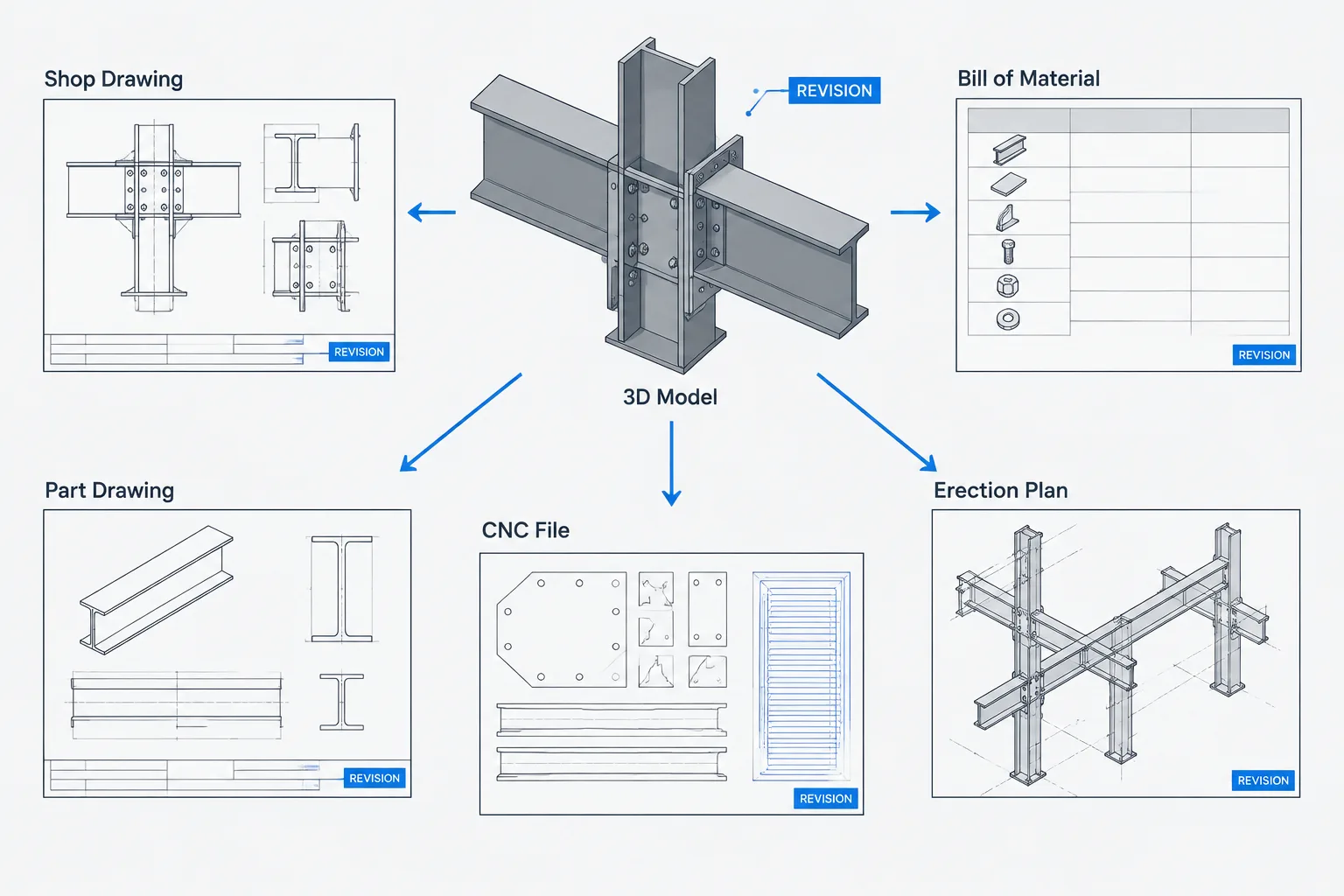
- Compare assembly dimensions, part details, material lists, and fabrication data before release.
Final Detailing Principle
A lap joint should be treated as a three-dimensional transfer zone, not simply as two outlines with matching holes. Its quality depends on coordinated overlap geometry, an accurate ply stack-up, aligned holes, usable bolt access, and a clearly represented load path.
When those relationships are shown explicitly, lap joints become easier to design-check, fabricate, assemble, and inspect. When they are left implicit, even a simple two-part connection can produce incorrect bolt lengths, mismatched holes, unintended offsets, or field fit-up problems.