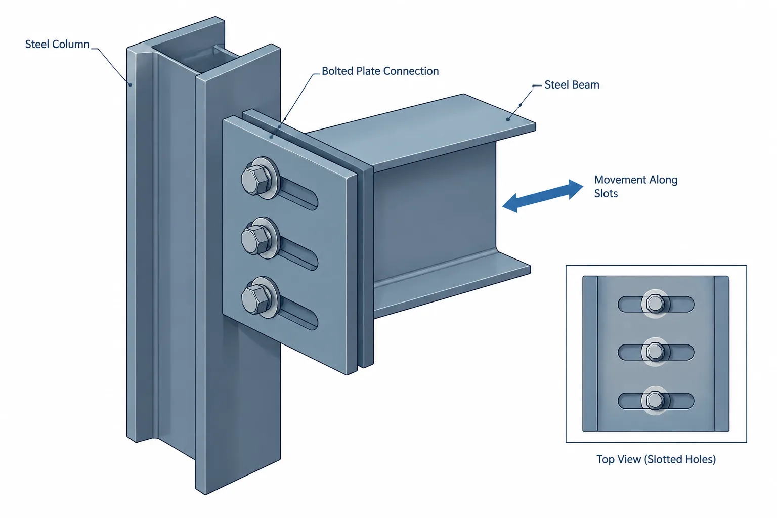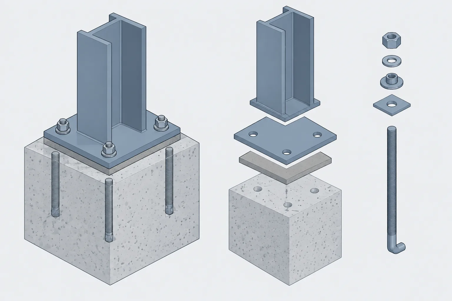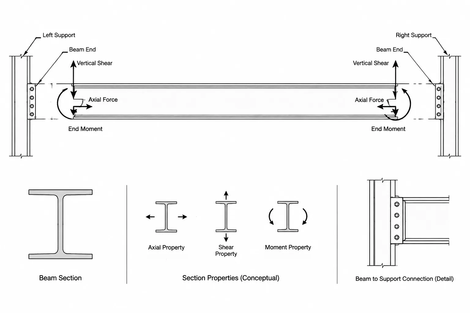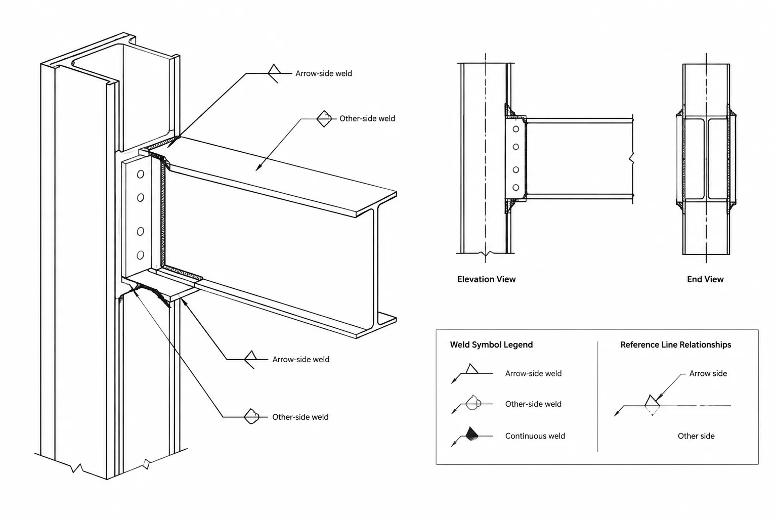
Structural steel weld symbols compress a large amount of fabrication information into a small drawing annotation. A symbol may identify the weld type, which side of the joint receives it, its extent, and whether supplementary instructions apply. The challenge is that the symbol does not stand alone: it must be interpreted together with the arrow location, member orientation, section views, connection details, and project notes.
This guide focuses on the drawing-reading and coordination principles behind weld symbols rather than weld design or acceptance criteria. Exact symbol use, weld requirements, and inspection provisions must follow the governing project documents and applicable welding standard.
The Main Parts of a Weld Symbol
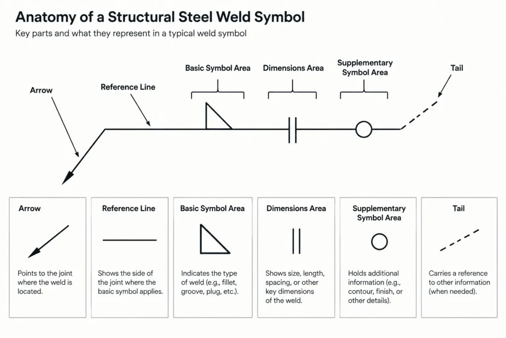
A typical weld callout is organized around a horizontal reference line. The arrow connects that line to the joint or component being identified. Additional information may appear around the line or in a tail.
- Arrow: Points toward the relevant joint, edge, interface, or member.
- Reference line: Provides the framework for locating the basic weld symbol and associated dimensions.
- Basic weld symbol: Indicates the general weld or joint form, such as a fillet, groove, plug, or slot weld.
- Dimensions: May describe weld size, length, spacing, groove geometry, or another required parameter.
- Supplementary symbols: Can communicate conditions such as all-around welding, field welding, contour, or finish.
- Tail: May contain a process, procedure reference, specification note, or other project-specific instruction. An unused tail may be omitted.
These parts should be read as a coordinated instruction. For example, a recognizable fillet symbol does not by itself establish the physical joint, weld extent, access, or whether the callout applies to the near face visible in the current view.
Arrow Side and Other Side
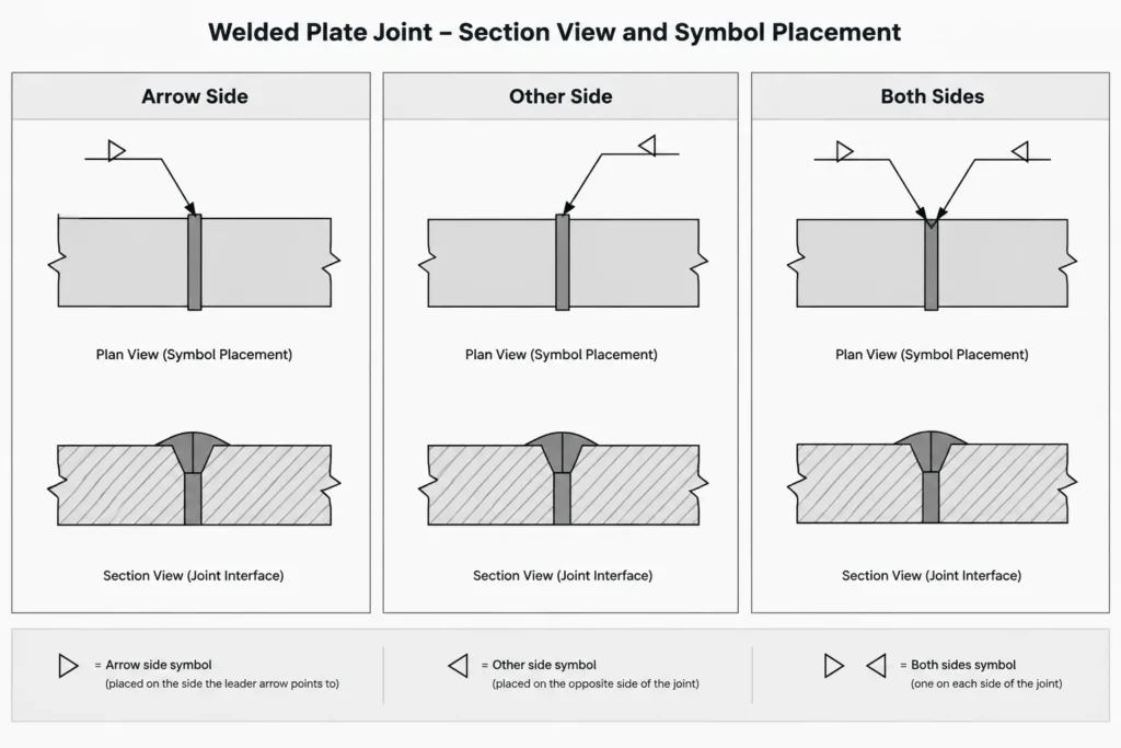
In common U.S. structural drawing practice, a basic weld symbol placed below the reference line generally applies to the arrow side of the joint. A symbol placed above the line generally applies to the other side. Symbols on both sides of the line indicate welding on both sides of the referenced joint.
The arrow side is not automatically the near side of the drawing, the left side of the member, or the face currently visible in elevation. It is the side of the joint to which the arrow refers. That distinction becomes important when members are shown in section, when a detail is mirrored, or when the arrow points to an edge shared by several plates.
Use the following reading sequence:
- Follow the arrow to its physical endpoint.
- Identify the two parts forming the joint.
- Determine which side of that joint the arrow designates.
- Read the symbol position relative to the reference line.
- Confirm the result against the plan, elevation, section, and three-dimensional member orientation.
If the joint side cannot be established without guessing, the detail needs clarification. Adding another view or moving the arrow is often safer than relying on a note to repair an ambiguous graphic.
The Arrow Points to a Joint, Not Merely a Plate
A common drafting mistake is to treat the arrow as though it labels an entire component. In most connection details, the intended subject is the interface between components. An arrow landing on a shear plate edge, for example, may refer to the joint between the plate and supporting member rather than every exposed edge of the plate.
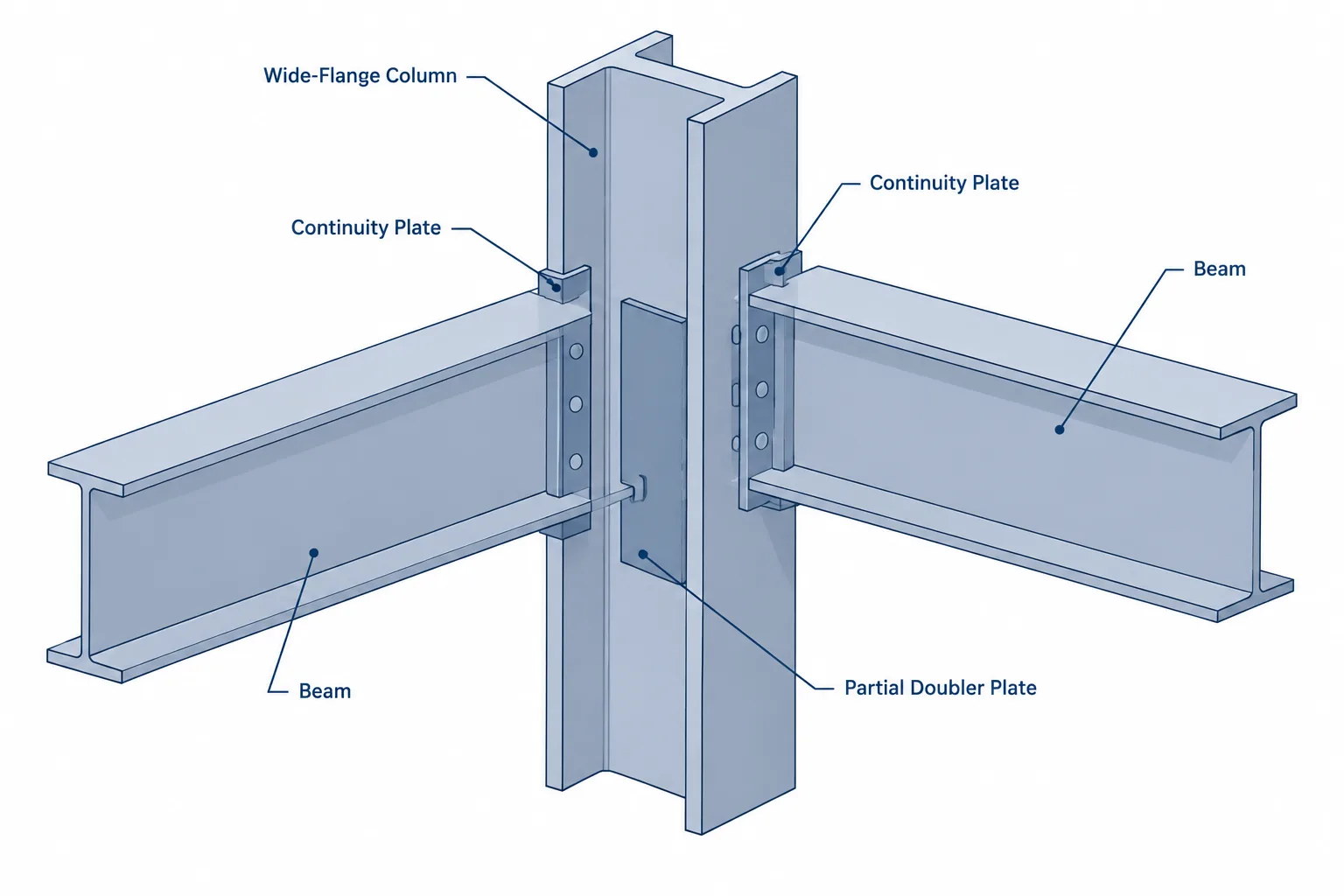
Closely spaced connection elements can make the endpoint unclear. Stiffeners, clip angles, continuity plates, doubler plates, and HSS walls may overlap in projection. A leader that appears clear at a large CAD zoom can become ambiguous when plotted.
Good practice is to place the arrowhead directly at the relevant interface and check the annotation at its intended sheet scale. Where several similar joints exist, use separate callouts, a clearly bounded typical note, or a detail that explicitly identifies the repeated condition.
Common Information and Where It Appears
| Information | Drawing function | Coordination question |
|---|---|---|
| Basic weld symbol | Identifies the general weld or joint type | Does the depicted joint geometry support that type? |
| Symbol above or below the line | Distinguishes other-side and arrow-side application | Can the joint side be determined from the view? |
| Size information | Defines a required weld or preparation dimension | Is the notation complete and consistent with the design information? |
| Length and spacing | Describes continuous or intermittent extent | Are start, stop, and end conditions clear? |
| All-around indicator | Extends the instruction around the referenced joint | Is a continuous physical path actually available? |
| Field-weld indicator | Identifies welding intended for field execution | Does the erection sequence provide access and fit-up? |
| Tail note | Adds a process or project-specific reference | Does it point to information available to fabrication and inspection personnel? |
Weld Length and Extent Need Geometric Context
A weld symbol may describe a weld length, but the drawing still needs to make its location understandable. A plate edge can be longer than the specified weld, and several possible start points may exist. Simply placing a length next to the symbol may not establish whether the weld is centered, starts at one end, stops at a cope, or continues around a corner.
For partial-length welds, show or dimension the controlling location when it matters. For repeated intermittent welds, make the pattern direction and applicable edge clear. Avoid assuming that fabricators will infer a centered pattern unless that intent is stated or unmistakably shown.
End conditions deserve particular attention near beam copes, flange transitions, rounded HSS corners, access holes, plate clips, and intersecting welds. The available physical edge may differ from the simplified linework in a general arrangement view.
All-Around Does Not Mean Everywhere on the Assembly
An all-around indicator applies around the joint identified by the arrow. It should not be interpreted as an instruction to weld every contacting edge in the assembly.
Before using an all-around callout, trace the intended joint as a continuous path. Ask whether the path is interrupted by another plate, a cope, an inaccessible face, or a change in joint configuration. A rectangular plate attached to a broad surface may have an obvious perimeter, while an attachment crossing a rolled-shape fillet or wrapping around an HSS corner may require more explicit depiction.
If different edges require different welds, separate callouts are generally clearer than one symbol that appears to cover unlike conditions.
Field and Shop Location Must Match the Connection Sequence
A field-weld designation affects more than symbol reading. It should agree with how the steel is assembled, shipped, erected, aligned, and accessed. A joint shown as field welded may become difficult to reach after decking, adjacent framing, piping, or architectural construction is installed.
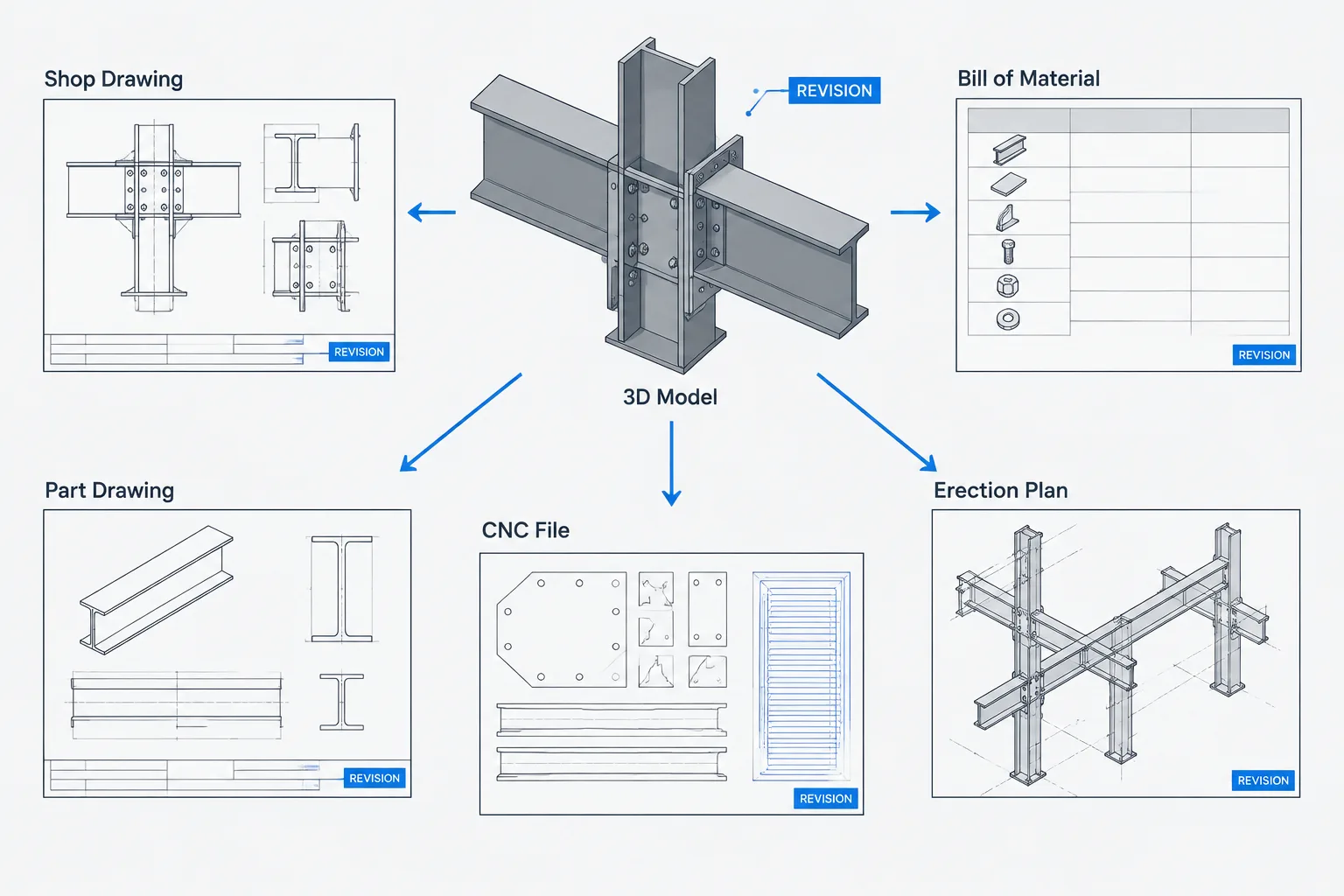
Likewise, a weld assumed to be completed in the shop may join parts assigned to separate shipping assemblies. Review weld callouts alongside piece marks, shipping splits, erection plans, and connection sequence. The weld location and the assembly breakdown must tell the same story.
Groove Weld Symbols Require Extra Care
Groove weld notation can communicate joint preparation as well as weld placement. The detail geometry should agree with the symbol: member edges, root region, backing or related components, and access must not contradict the callout.
Some groove conditions are asymmetric, making the arrow endpoint and symbol orientation especially important. Do not mirror or rotate a detail without checking whether the prepared component has changed sides. A visually symmetric connection may contain a joint preparation that is not symmetric.
When the shop drawing is based on design information that does not fully define the joint preparation, the detailer should use the project’s clarification process rather than inventing missing geometry.
CAD Practices That Reduce Weld-Symbol Errors
- Use associative leaders where practical. A detached arrow can remain behind when connection geometry moves.
- Avoid exploding symbols into loose linework. Maintaining a complete annotation object reduces accidental loss of a flag, tail, or dimension.
- Check mirrored details. Mirroring can reverse graphics without preserving the intended arrow-side relationship.
- Review plotted output. Arrowheads and symbols that are clear in model space may overlap object lines on the sheet.
- Keep symbol scale consistent. Excessively small annotations are easy to misread, while oversized symbols can obscure the joint.
- Coordinate typical details. A typical weld note should define its scope and should not conflict with specific connection callouts.
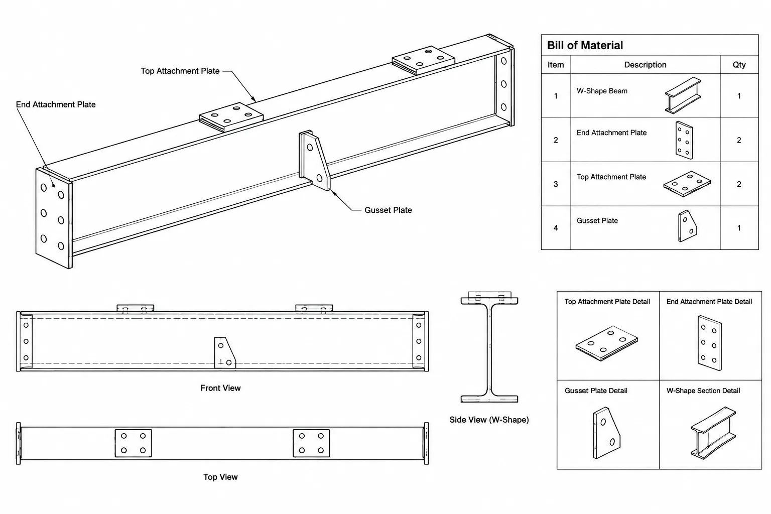
- Compare views. Plan, elevation, and section views should describe the same welded interface.
A Practical Weld-Symbol Review Checklist
Before issuing a structural steel detail, review each weld callout with these questions:
- Does the arrow terminate at one identifiable joint?
- Can the arrow side and other side be determined without assumption?
- Does the basic symbol match the physical joint shown?
- Are weld extent, start location, and termination clear?
- Does an all-around instruction follow a real, continuous path?
- Do field and shop designations agree with assembly and erection planning?
- Are both-side welds physically accessible?
- Has a mirrored, copied, or rotated detail changed the intended side?
- Do member fillets, HSS corners, copes, or adjacent plates affect access?
- Are project notes and specific symbols consistent?
Read the Symbol and the Steel Together
A weld symbol is not a substitute for understanding the connection geometry. Reliable interpretation comes from combining the annotation with the actual parts, their orientation, the joint interface, and the fabrication sequence.
For drafters, the central rule is simple: make the arrow point to an unmistakable joint and make the symbol agree with what can physically be fabricated. For reviewers, trace the joint rather than reading the callout in isolation. That approach catches many side, extent, access, and sequencing errors before they reach the shop or field.