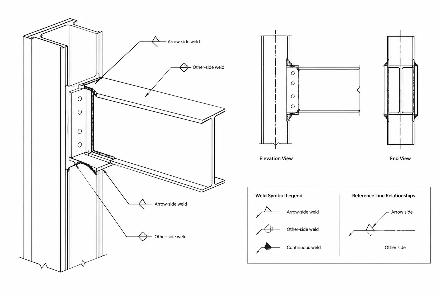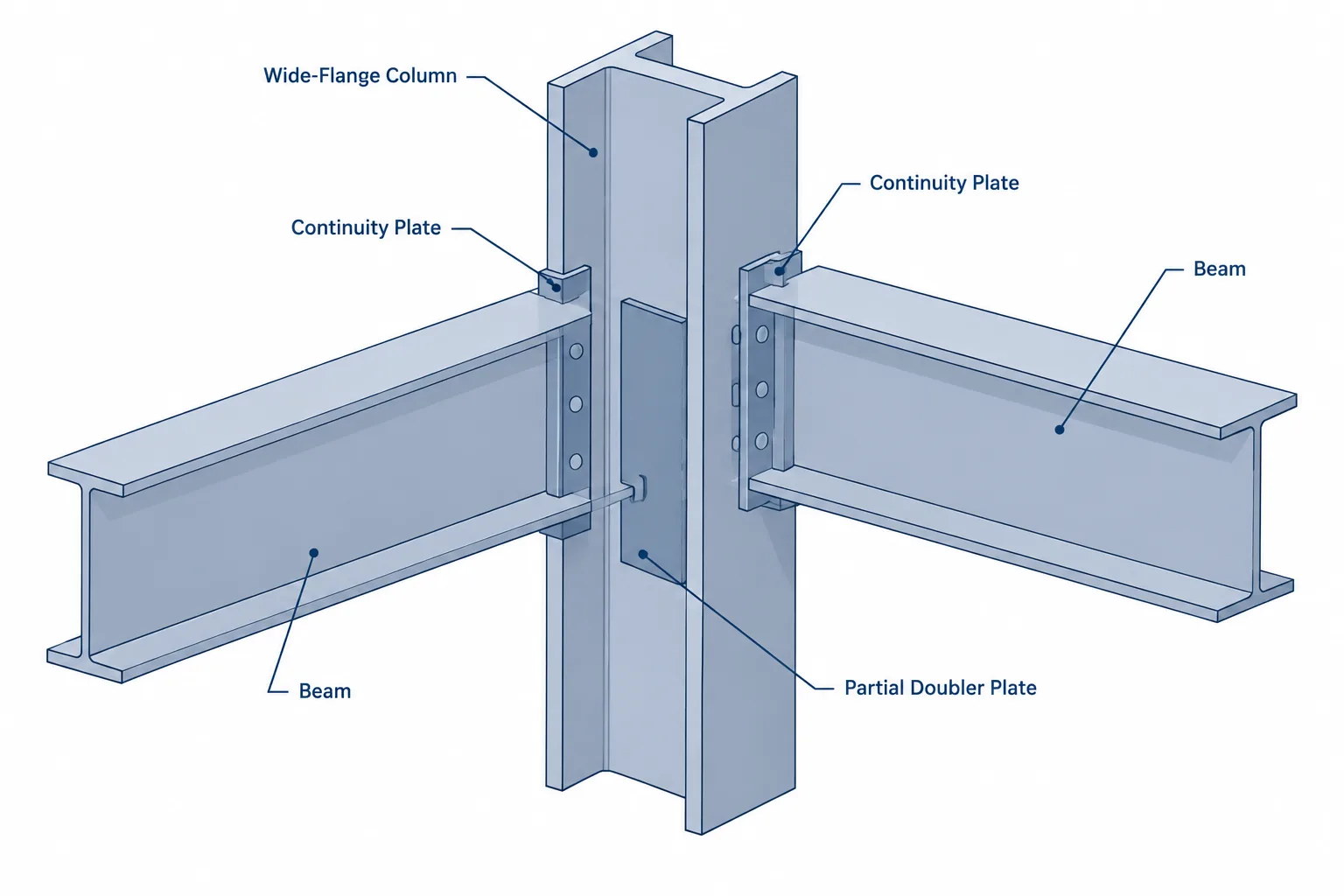
Structural steel information may be located from column grids, survey coordinates, member work lines, faces of steel, or part-level fabrication datums. These references can describe the same assembly, but they are not interchangeable. A hole located correctly from a plate edge may still be wrong in the building if the plate assembly was positioned from an incorrect grid intersection.
A reliable detailing workflow therefore separates three questions: Where is the steel in the project? How is the member oriented? Where are its individual features located? Understanding these levels helps prevent shifted columns, mirrored connections, incorrect elevations, and coordinate data that appears precise but does not match the controlling drawings.
The Main Coordinate Levels in a Steel Project
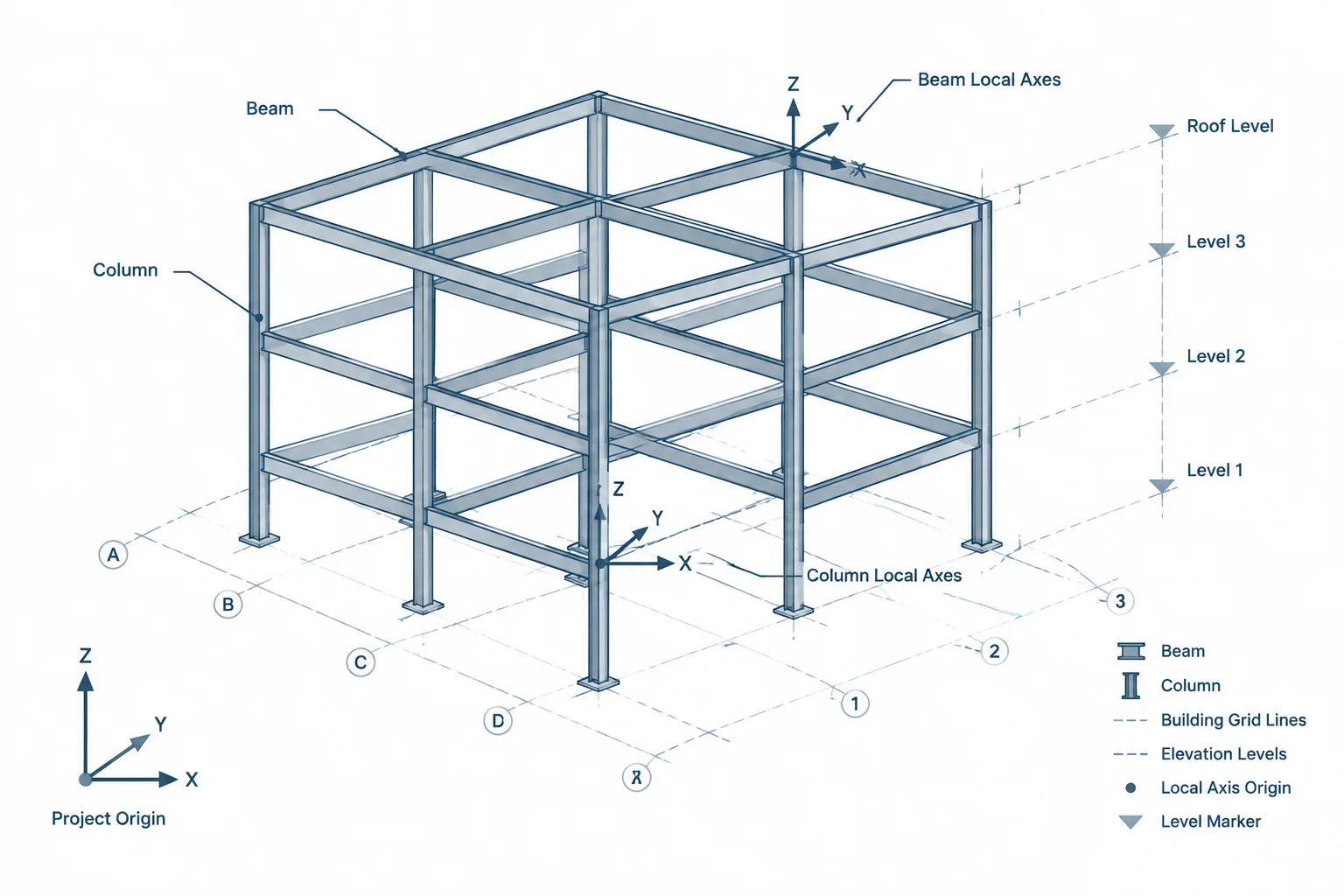
Structural steel coordinate systems are easiest to manage when divided into project, member, and part references. Different software may use different names, but the underlying hierarchy is similar.
| Reference level | Typical purpose | Common examples |
|---|---|---|
| Project or global | Locates objects within the entire structure or site | Project origin, northing, easting, elevation |
| Structural grid | Organizes primary framing and communicates design layout | Lettered and numbered grid lines, offsets from grids |
| Member local | Defines orientation and feature positions along a member | Start and end, longitudinal axis, top, bottom, left, right |
| Assembly datum | Controls attached parts within a fabricated assembly | Beam end, column work point, connection face |
| Part datum | Locates holes, cuts, and edges on an individual piece | Plate corner, edge, centerline, bend line |
Problems arise when data from one level is treated as though it belongs to another. For example, a column centerline may be placed at a global coordinate, while its base plate holes are dimensioned from the plate centerlines. The anchor rods may instead be controlled by a grid intersection. All three references must agree, but each serves a different task.
Project Origins and Global Coordinates
A global coordinate system provides a common spatial framework for the complete model. It generally includes two horizontal directions and a vertical direction. The project origin may be selected for modeling convenience, inherited from survey information, or established through project coordination.
The origin should not be assumed to coincide with a building grid intersection. Some models use a remote survey origin, while others use a convenient structural reference near the framing. A project may also contain transformed or shared coordinate systems used to align models from different disciplines.
Before importing, exporting, or referencing steel geometry, confirm:
- Which origin is being used.
- Which direction represents project north or the primary building axis.
- Whether elevations are relative or tied to a broader project datum.
- Whether an offset or rotation is applied during file exchange.
- Whether coordinates refer to member centerlines, insertion points, or physical faces.
A long coordinate value does not prove that an object is accurately located. It only reports a position relative to a selected origin. Model alignment must still be checked against recognizable grids, levels, and framing intersections.
Structural Grids Are Layout References, Not Physical Edges
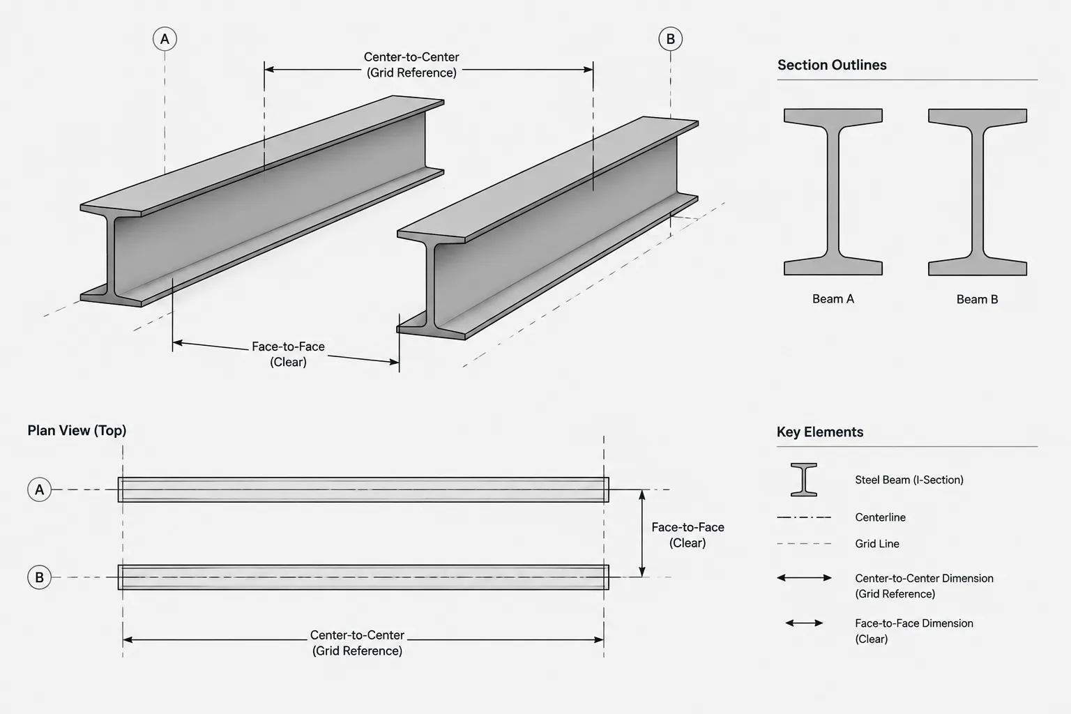
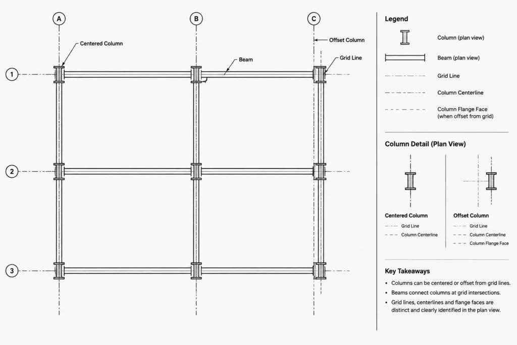
Grid lines are commonly used to locate columns, walls, and major framing. They provide stable references that remain understandable across plans, elevations, and coordination models. However, a grid is an abstract control line. It does not automatically represent the face or center of every steel member near it.
A column may be centered on a grid, offset from it, or centered in one direction while aligned by a flange face in the other. Perimeter framing may be dimensioned from a property-related control line while the steel sits inside that line. Transfer framing and sloping members may cross several grids without using any intersection as a fabrication datum.
When reading a grid-based location, identify exactly what the dimension reaches:
- Member centerline or work line
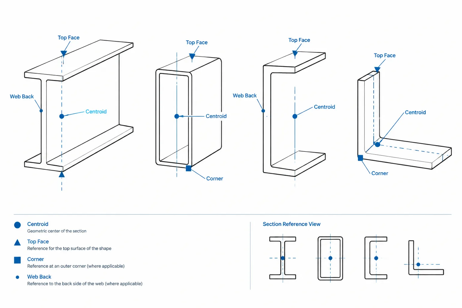
- Column flange face
- Column web centerline
- Beam end or bearing line
- Edge of base plate
- Edge of slab or another nonsteel reference
This distinction is especially important when a member size changes. If the centerline remains fixed, its faces may move. If a face is the controlling datum, the member centerline may move instead.
Local Member Axes and Direction
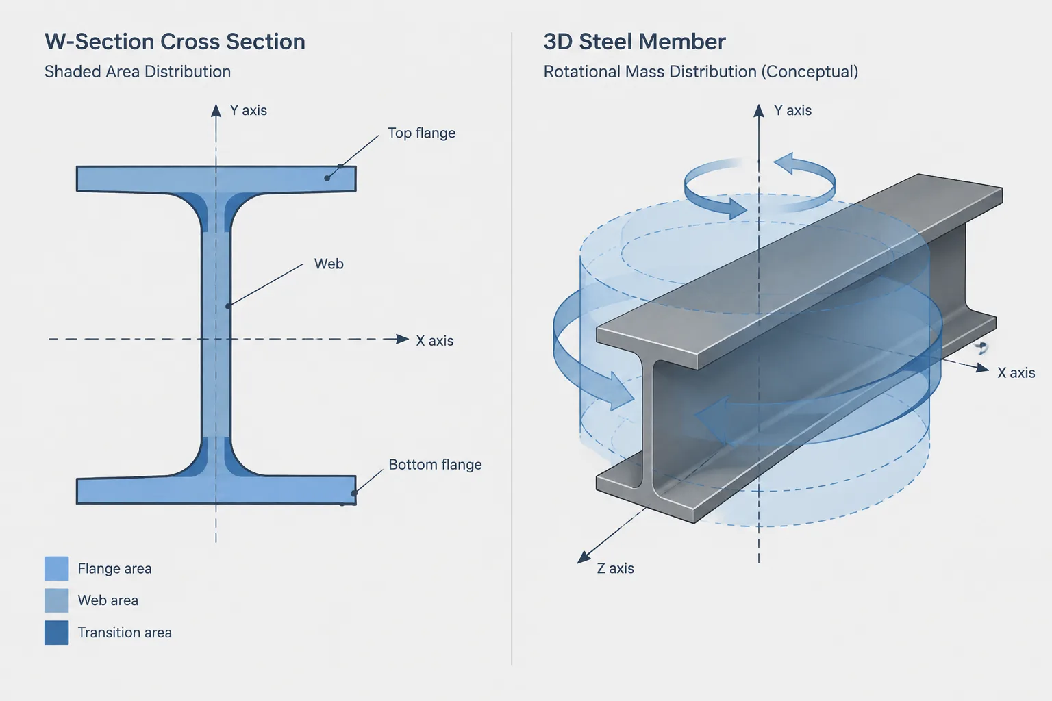
Each modeled member also has a local coordinate system. One axis typically follows the member length, while the other two describe the section orientation. Local axes allow connection components, offsets, and cuts to be defined relative to the member rather than the whole building.
Member direction matters because many local descriptions depend on looking from the start toward the end. Reversing a member can exchange left and right, near and far, or start and end. The physical shape may initially appear unchanged, but connection rules, cope locations, plate sides, bolt coordinates, and piece-mark logic may be affected.
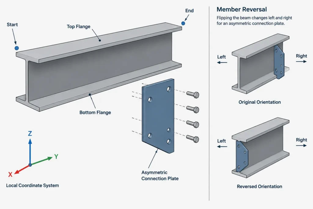
For sloped or skewed members, local directions are particularly useful. Global vertical is not necessarily the same as the member’s local section direction. Likewise, a dimension measured along a sloped member is different from its horizontal projection.
Useful local-axis checks
- Display the member start and end before placing asymmetric connections.
- Verify which local direction corresponds to the top flange or intended HSS face.
- Check section rotation after copying or mirroring members.
- Confirm whether offsets are measured globally or perpendicular to the member.
- Recheck local axes after replacing one shape type with another.
Assembly Datums and Fabrication Dimensions
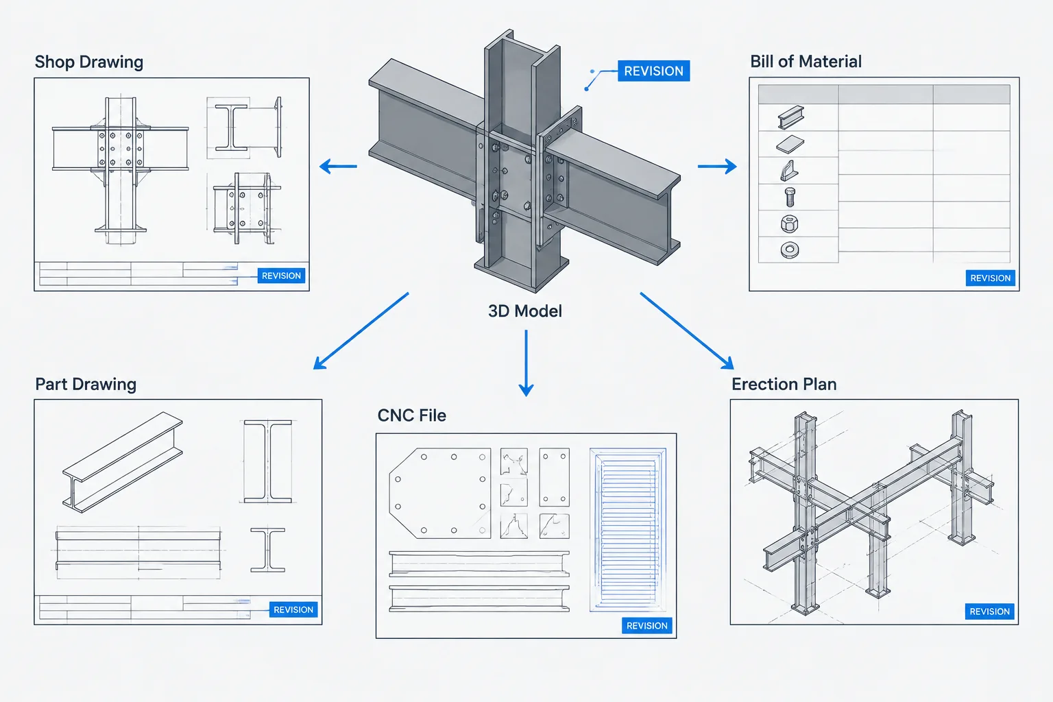
Shop drawings usually need dimensions that can be reproduced during fabrication. Global coordinates alone are rarely the clearest way to manufacture an assembly. A beam may be located globally in the model, but its holes and attached plates are more practically dimensioned from a beam end, work point, web centerline, flange surface, or another accessible datum.
A good fabrication datum should be identifiable on the actual piece and should support the intended sequence of cutting, drilling, fitting, and inspection. Dimensions should not require the shop to reconstruct the entire building coordinate system merely to locate a clip angle or bolt group.
Common assembly-level references include:
- A finished or square-cut member end
- A theoretical work point beyond the physical end
- The centerline of a column or beam web
- The outside face of a flange
- Top of steel
- A bearing surface or connection plane
If a theoretical point controls a dimension, the drawing should make that relationship understandable. A work point cannot be measured directly unless it is supported by other dimensions or geometry.
Part Coordinates for Plates and Connection Material
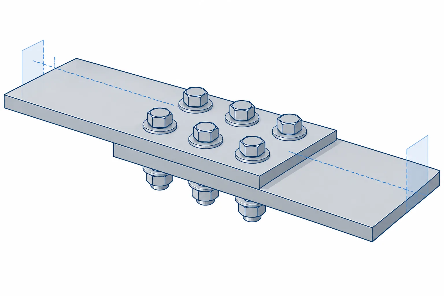
Individual plates and connection parts need their own unambiguous datums. Hole locations are commonly organized from edges, centerlines, or a designated plate corner. Cutouts, slots, notches, and bend lines should use the same coordinate logic where practical.
Mixing datums can create unnecessary calculation and increase the chance of errors. For example, locating one hole row from the left edge and another from the plate centerline may be valid, but the reason should be clear. A consistent baseline often makes both checking and machine-data preparation easier.
The selected origin should also remain valid if the part is rotated for nesting. Nesting orientation on a sheet is a production decision; it should not silently redefine the engineering or detailing datum used to describe the part.
Coordinate Transformations During Model Exchange
Steel geometry often passes through several environments, including analysis models, coordination models, detailing software, CAD backgrounds, survey files, and fabrication outputs. Each transfer may introduce an origin shift, axis rotation, unit conversion, or interpretation of insertion points.
A practical exchange check should use more than a visual overlay. Compare several known references distributed around the structure. Suitable checks include grid intersections, column work points, level elevations, and distinctive framing locations. One matching point verifies translation, but it may not reveal a rotation, scale problem, or mirrored axis.
Keep a record of any transformation applied during import or export. If a temporary move is needed for modeling convenience, preserve enough information to return the model to the agreed project coordinates.
A Practical Coordination Checklist
- Identify the controlling project origin, grid system, and elevation datum.
- Confirm whether model coordinates are shared, transformed, or local to a file.
- Determine what each grid dimension locates: centerline, work line, or face.
- Check member start, end, local axes, and section rotation.
- Use fabrication datums that can be established on the physical member.
- Keep hole and cut coordinates consistent within each part.
- Verify imported geometry at multiple separated control points.
- Recheck coordinates after mirroring, rotating, or changing member sizes.
- Do not treat displayed coordinate precision as proof of dimensional accuracy.
- Resolve conflicting references before releasing drawings or machine data.
Choosing the Right Reference for the Task
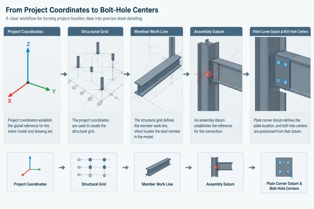
No single coordinate system should control every drawing operation. Project coordinates are valuable for model alignment and field layout. Grids communicate the structural arrangement. Local member axes control orientation and connection placement. Assembly and part datums support fabrication.
The goal is not to eliminate these different references, but to maintain a traceable relationship among them. A well-coordinated steel model should let a reviewer move logically from a building grid, to a member work line, to an assembly datum, and finally to a hole or cut location without encountering an unexplained shift or reversal.