Tag: CAD workflow
-
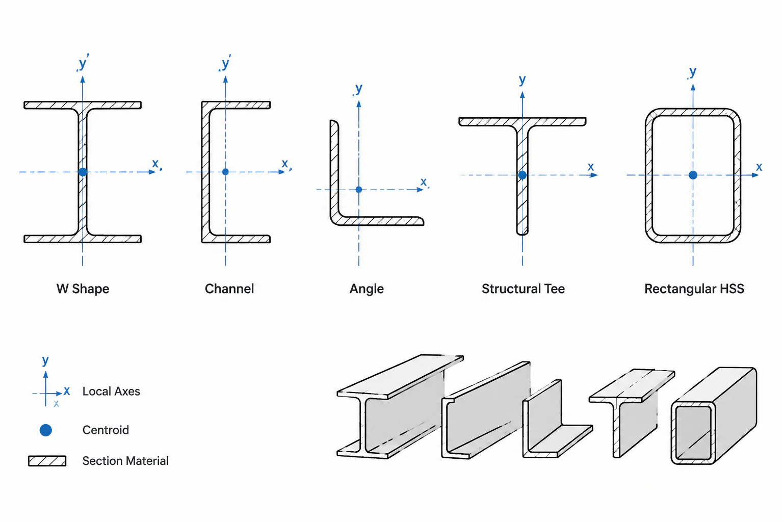
Centroid Coordinates in Steel Shape Tables: x̄, ȳ, Reference Axes, and CAD Placement
Learn how to interpret x-bar and y-bar centroid coordinates for W shapes, channels, angles, tees, and HSS, including reference origins and CAD checks.
Written by
-
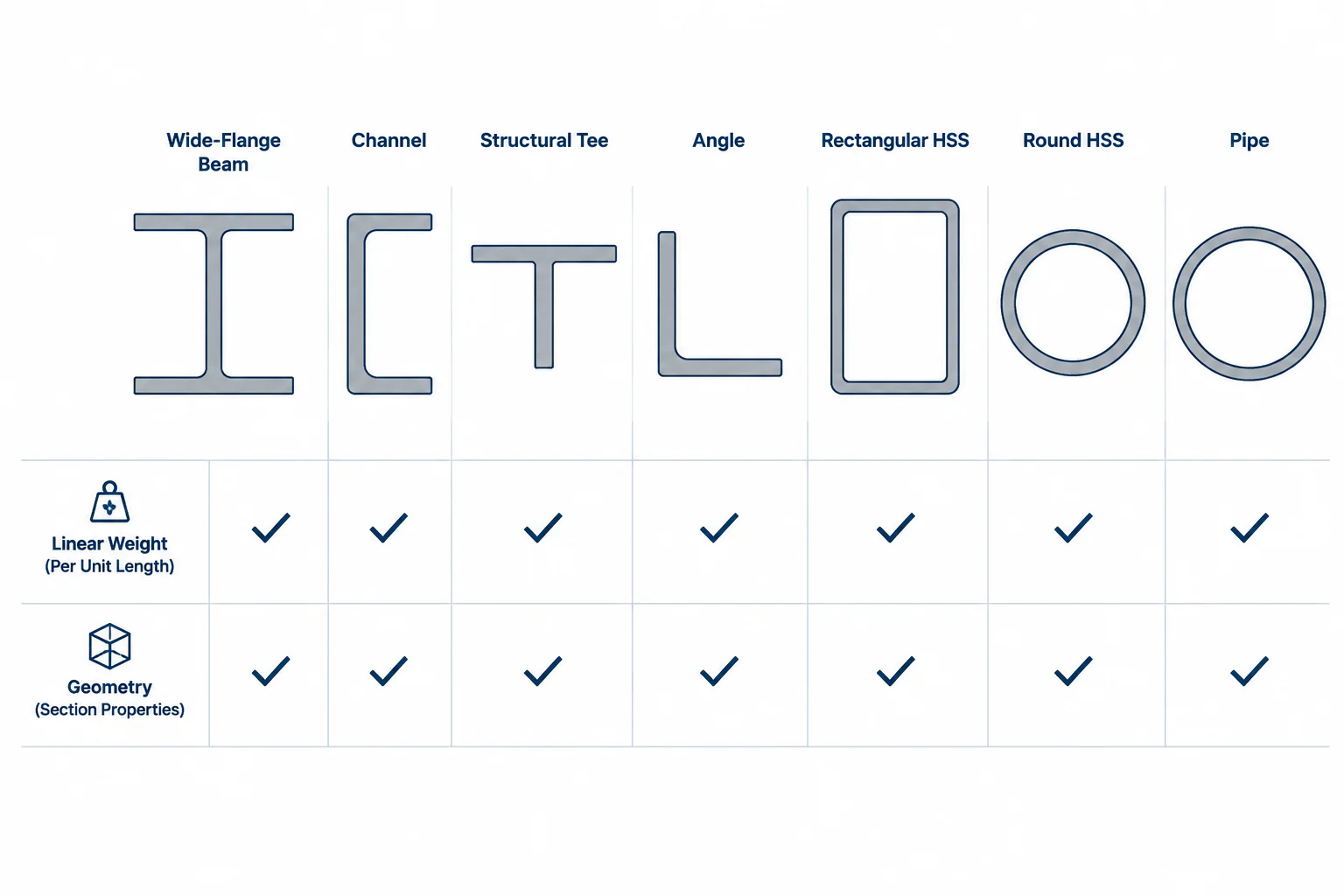
Reading Steel Shape Designations: Where Weight per Foot Appears—and Where It Does Not
Learn which structural steel designations include nominal weight per foot, which describe geometry instead, and how to estimate member weight correctly.
Written by
-
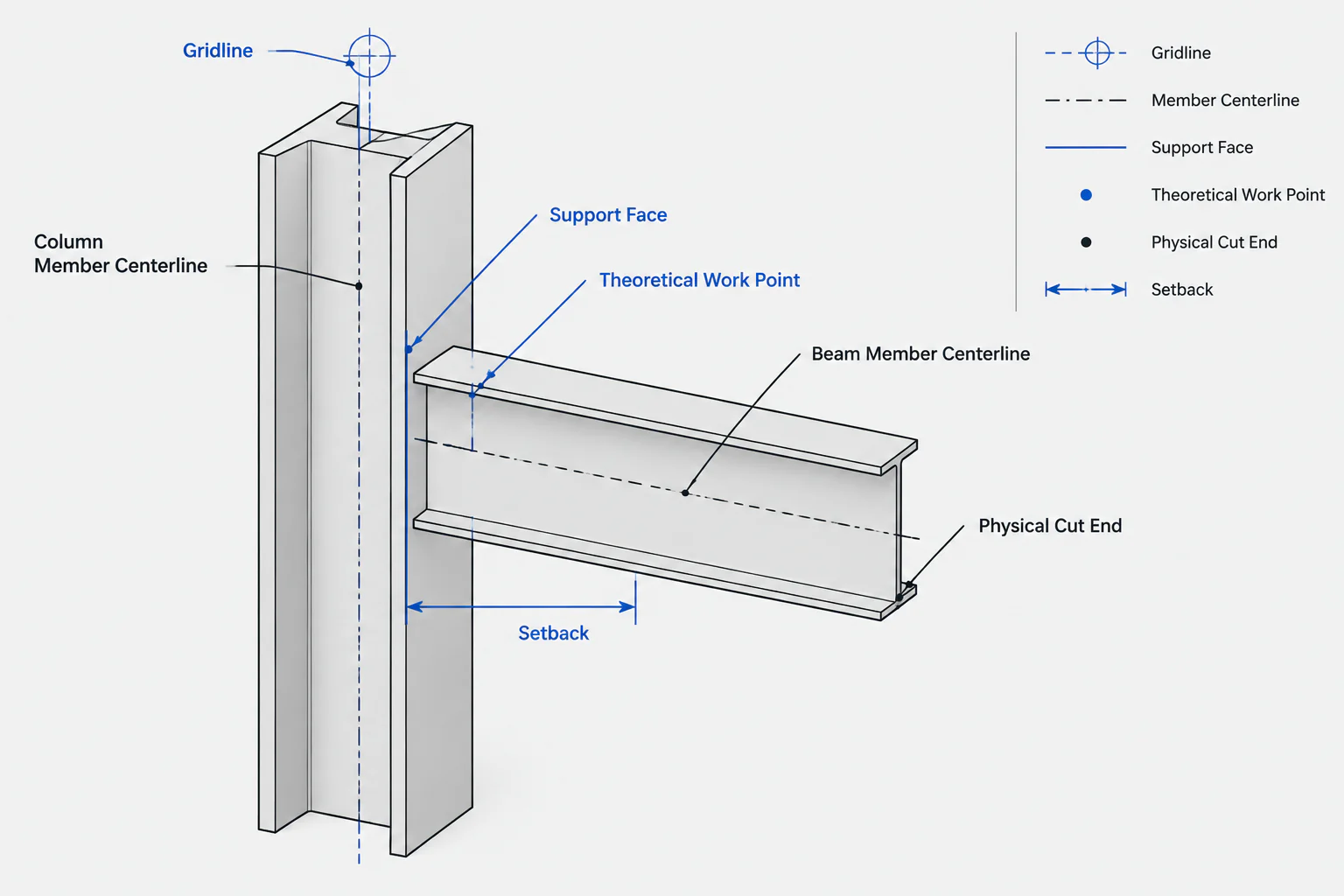
Work Points, Member Centerlines, and Setbacks in Structural Steel Detailing
Learn how work points, member centerlines, support faces, setbacks, and cut lines control structural steel detailing and CAD geometry.
Written by
-
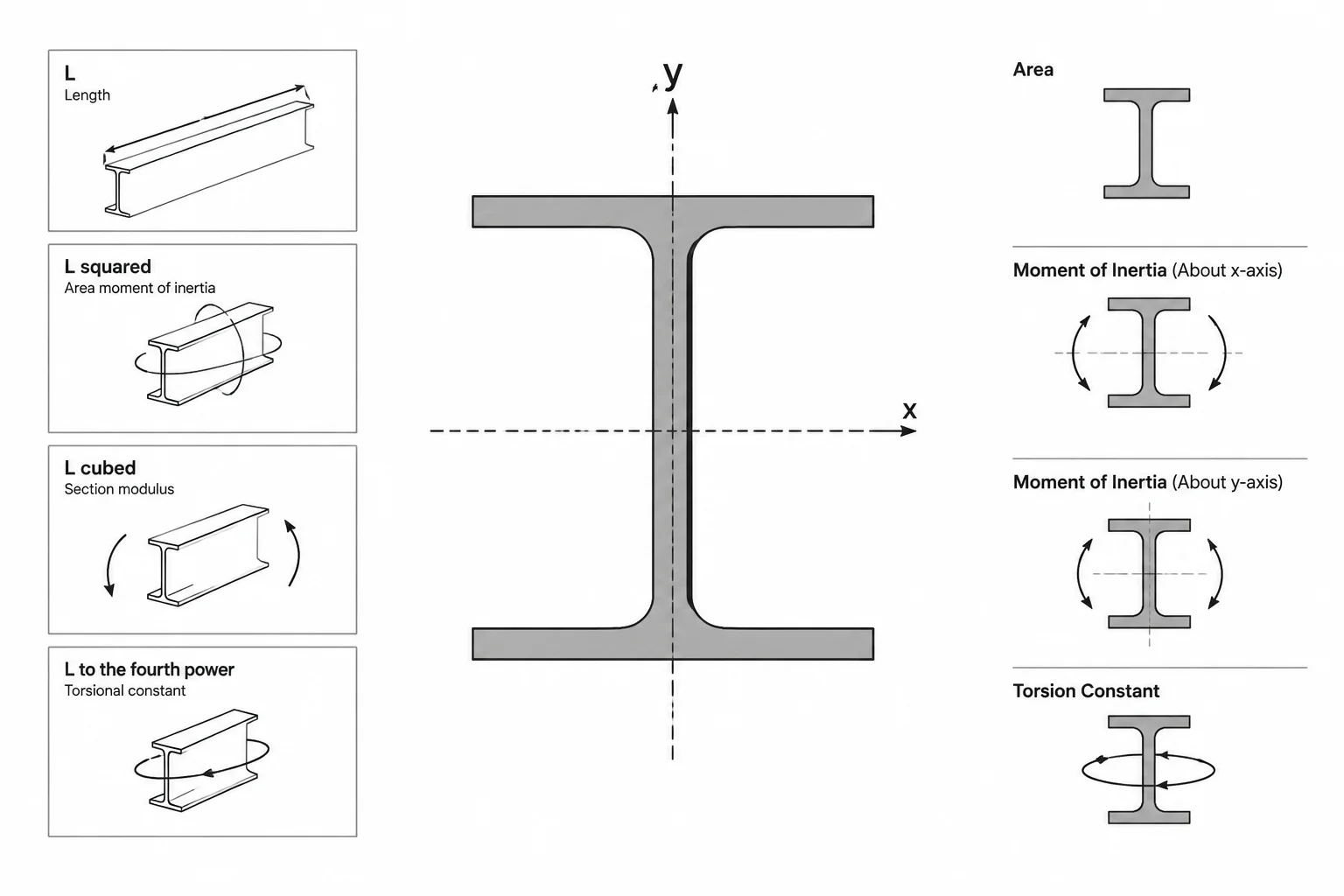
Steel Section Property Units: How to Read and Convert A, I, S, Z, r, J, and Cw
Learn the units used for steel section properties, why dimensional exponents matter, and how to convert shape data without common CAD and calculation errors.
Written by
-
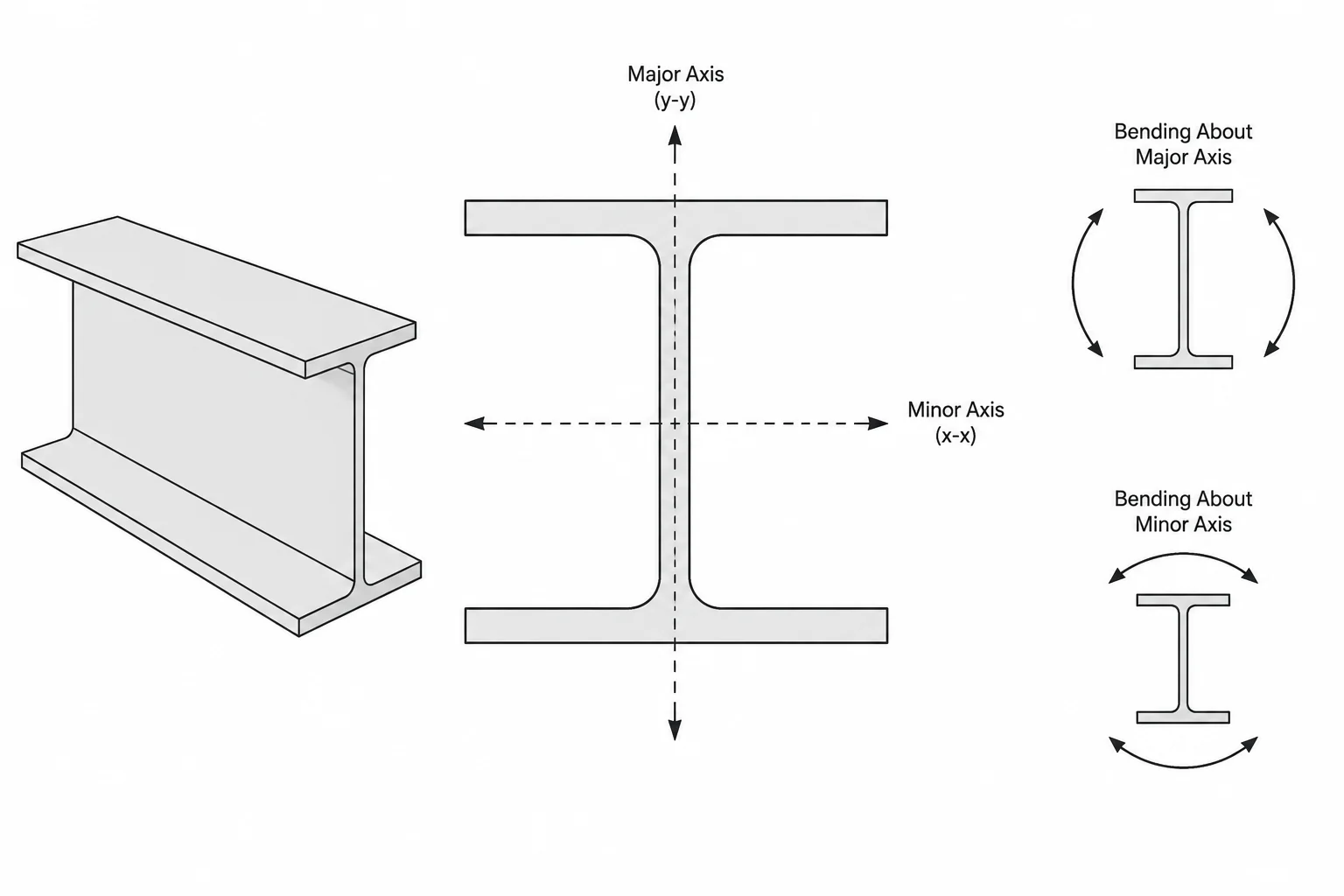
Strong Axis vs. Weak Axis in Structural Steel Sections
Learn how strong-axis and weak-axis bending relate to Ix, Iy, Sx, Sy, orientation, and detailing for W-shapes, channels, angles, tees, and HSS.
Written by
-
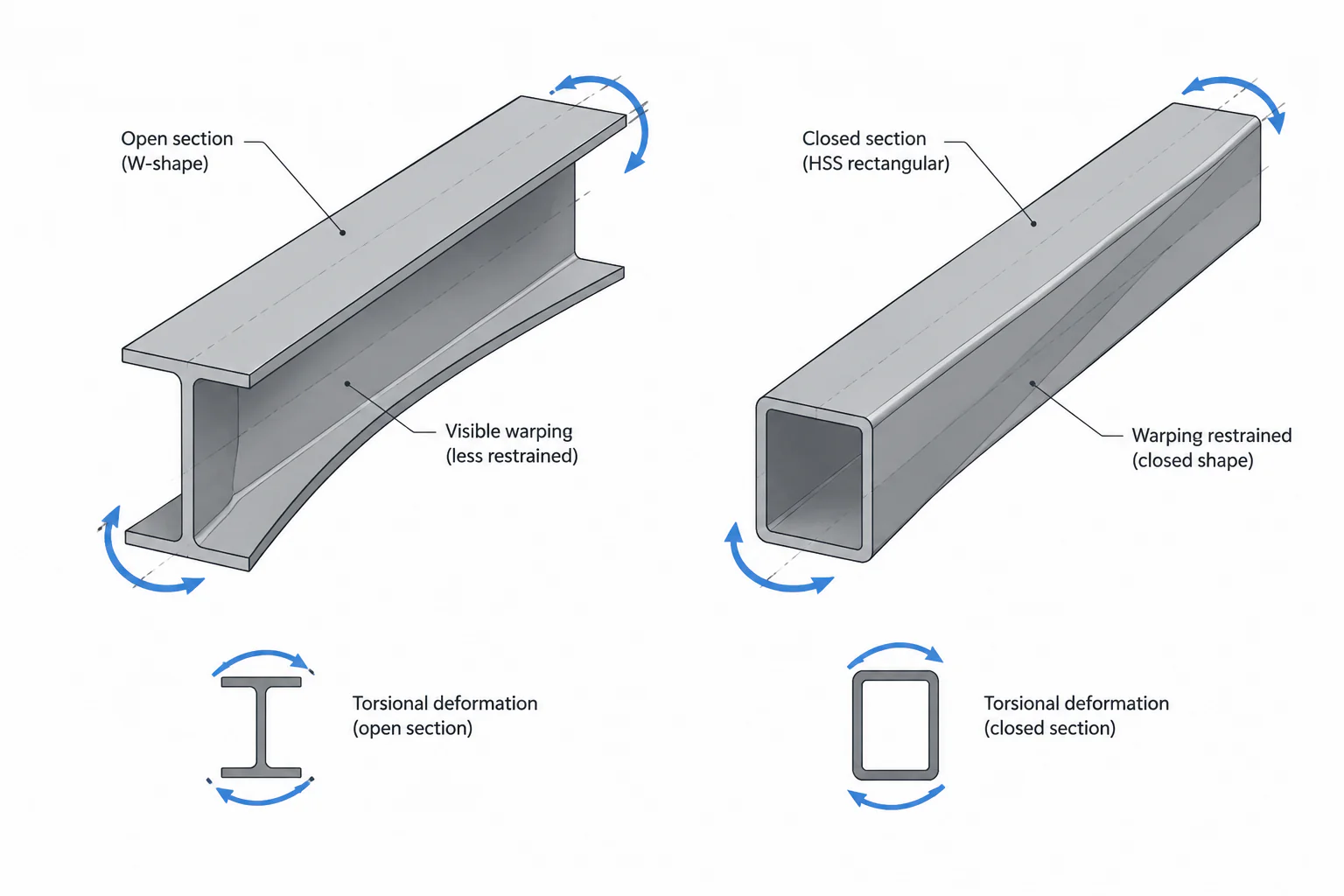
Torsional Constant J and Warping Constant Cw in Steel Shape Tables
Learn what J and Cw mean in structural steel shape tables, how open and closed sections resist torsion, and how to use these properties in design and CAD workflows.
Written by
-
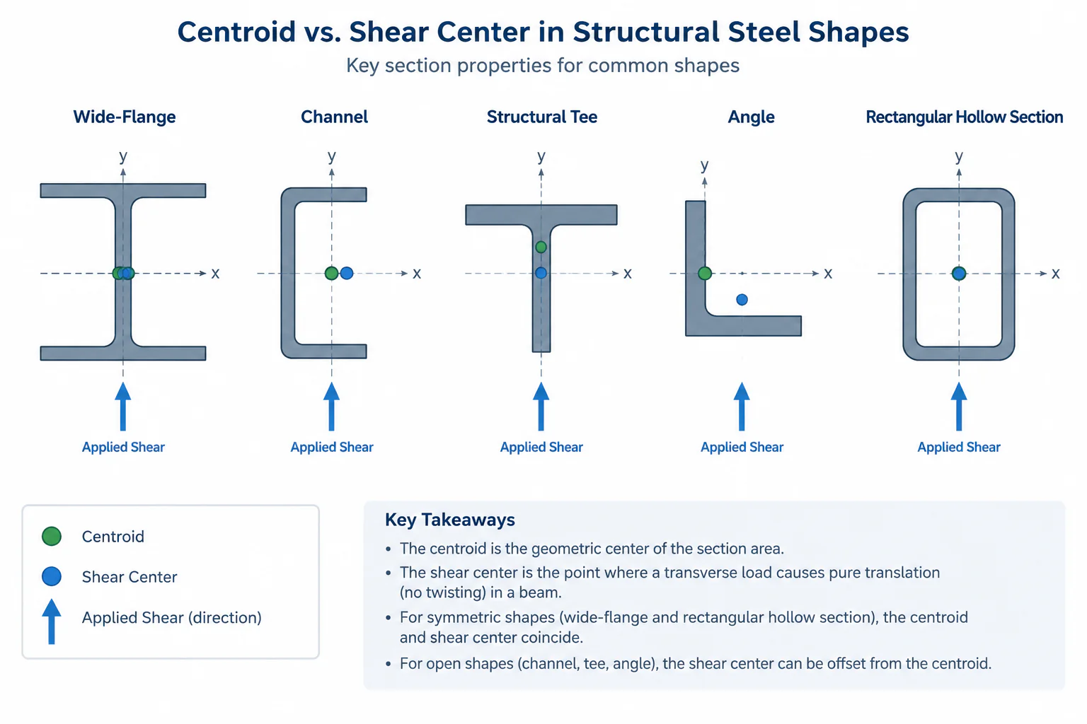
Shear Center vs. Centroid in Structural Steel Shapes
Learn how the shear center differs from the centroid in W-shapes, channels, tees, angles, and HSS, with practical detailing and CAD guidance.
Written by