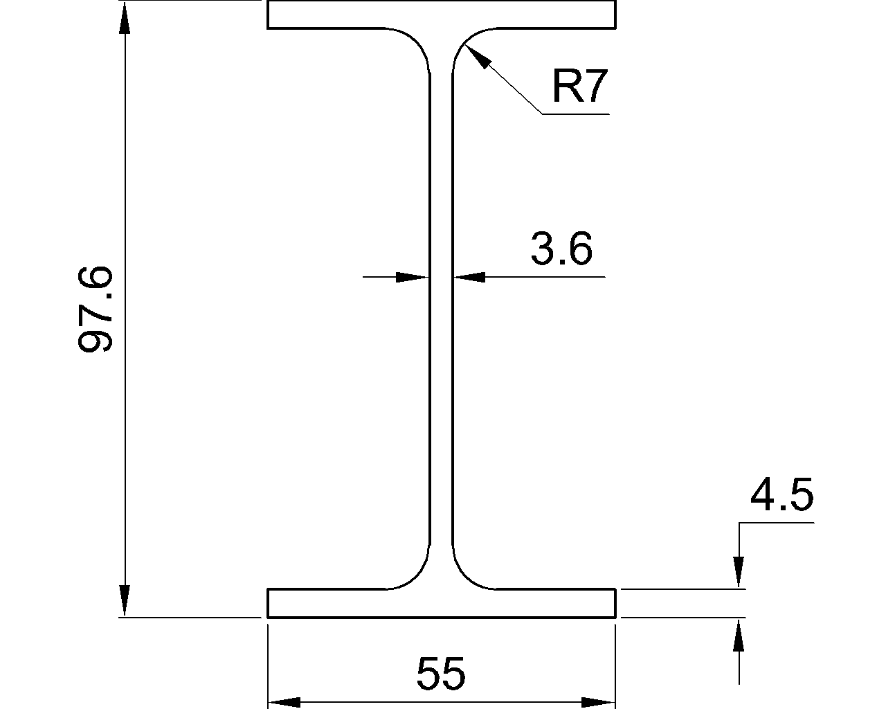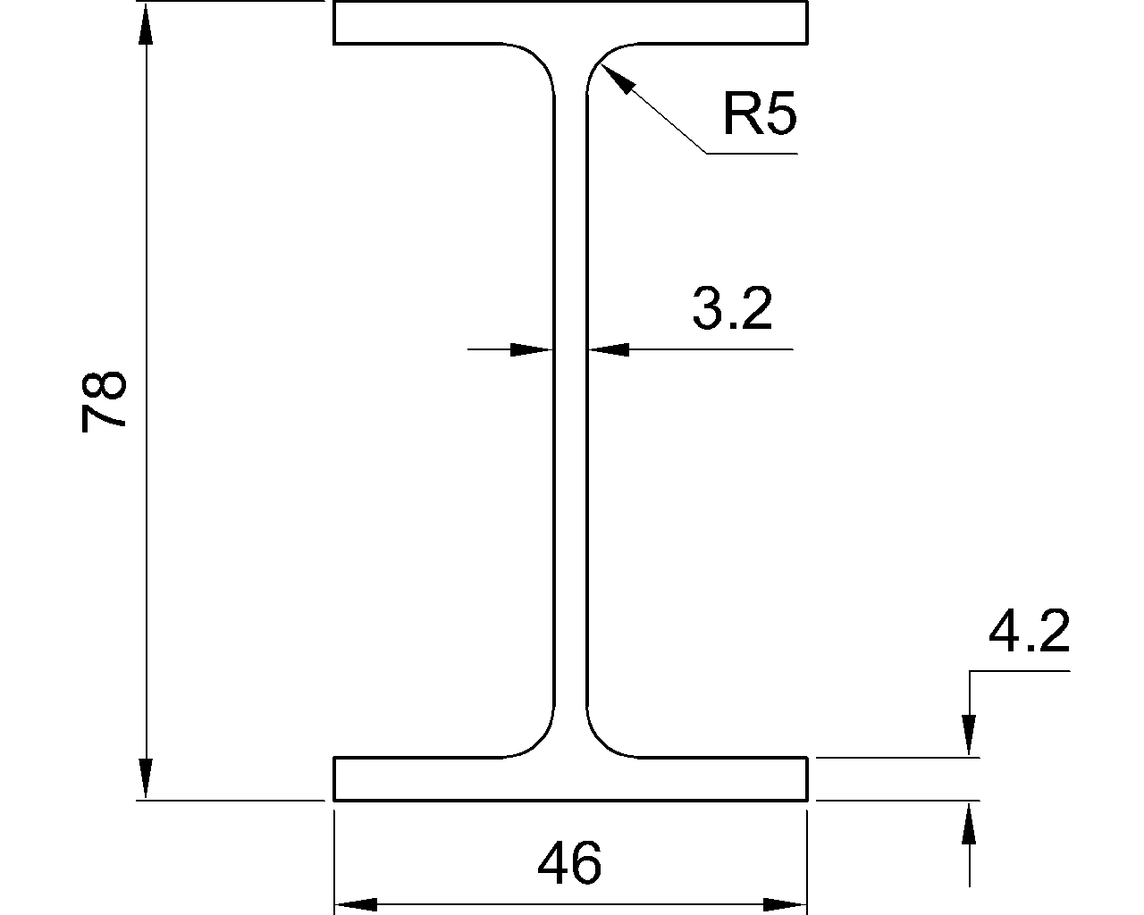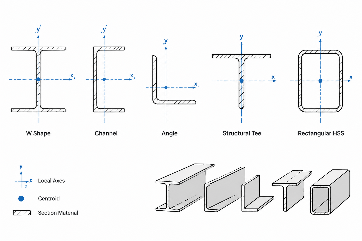
Steel shape tables often locate a section’s centroid with coordinates written as x̄ and ȳ, sometimes shown as x-bar and y-bar. These values may appear straightforward, but they are easy to misuse when the table’s origin, axis direction, or shape orientation is not understood. The issue is especially important for channels, angles, structural tees, and other sections whose centroid does not coincide with the visual center of a bounding box.
Centroid coordinates help establish analytical axes, place section geometry in CAD, calculate eccentricities, and assemble built-up members. They are geometric properties of the cross-section, not instructions for locating a member in a building. A reliable workflow therefore separates the section’s local coordinate system from project grids, elevations, work points, and connection geometry.
What Is the Centroid of a Steel Cross-Section?
The centroid is the area-weighted center of a cross-section. If a section is made from material of uniform density, its cross-sectional centroid also corresponds to its center of mass for a slice of constant thickness along the member. In shop and design conversations, it may informally be called the center of gravity, although centroid is the more precise term when discussing section geometry.
The first moments of area about axes passing through the centroid are zero. Section properties such as moment of inertia, section modulus, and radius of gyration are commonly reported about centroidal axes unless a table states otherwise.
The centroid should not be confused with:
- The geometric center of a bounding box: the midpoint between a shape’s extreme limits.
- The shear center: the point through which a transverse load can act without producing twist under idealized conditions.
- A work point: a drafting or layout reference selected to control member placement.
- A connection centerline: a line associated with bolts, welds, plates, or framing geometry.
- The neutral axis: an axis of zero longitudinal strain for a particular bending condition; for common elastic analysis of a homogeneous section, it passes through the centroid.
How x̄ and ȳ Coordinates Are Defined
A centroid coordinate has meaning only when its reference origin and coordinate directions are known. In general, x̄ is the horizontal distance from a stated y-axis to the centroid, while ȳ is the vertical distance from a stated x-axis to the centroid. The exact notation and origin convention can vary among shape references, software libraries, and CAD resources.
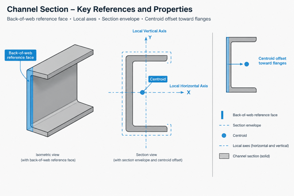
One source may measure from the lower-left corner of the overall section envelope. Another may measure from the back of a channel web, the outside face of an angle leg, or a centerline. A value must not be transferred between sources until those conventions have been compared.
Read the Diagram Before Reading the Value
A shape-table sketch normally communicates four essential items:
- The displayed orientation of the section
- The origin or face from which each distance is measured
- The positive directions of the local axes
- Whether the shown axes are centroidal, reference, or principal axes
If the diagram is absent, treat the coordinate as incomplete information. Do not assume that x̄ is measured from the leftmost edge or that ȳ is measured from the bottom.
How Symmetry Affects Centroid Location
| Shape type | Typical symmetry | Centroid implication |
|---|---|---|
| W and similar doubly symmetric I-shapes | Symmetric about both primary centerlines | The centroid lies at the intersection of the web centerline and mid-depth line. |
| Round, square, and rectangular HSS | Normally symmetric about both centerlines | The centroid lies at the geometric center of the overall section. |
| Channel | Usually symmetric about one axis | The centroid lies on the mid-depth axis but is offset horizontally from the web reference face. |
| Structural tee | Usually symmetric about the stem centerline | The centroid lies on the stem centerline but is not generally at half the overall depth. |
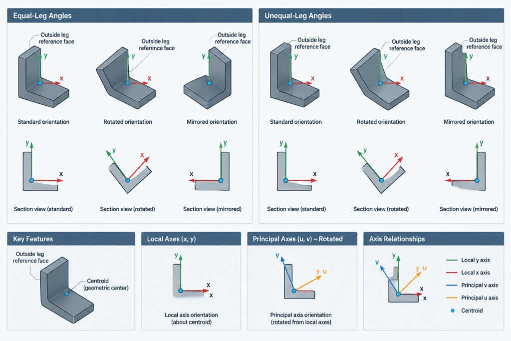
| Equal-leg angle | Symmetric about a diagonal bisector | Its coordinates may be equal when measured consistently from corresponding outside leg faces, but its principal axes are rotated. |
| Unequal-leg angle | No comparable leg symmetry | Both centroid coordinates depend on the stated orientation and origin. |
Rolled fillets and rounded corners contribute area. Consequently, a centroid derived from a simplified sharp-corner outline may differ from a published property based on a more representative section model. For accurate reference work, use verified tabulated properties and understand how the associated geometry was defined.
Shape-Specific Interpretation
W Shapes and Other Doubly Symmetric Sections
For a doubly symmetric W shape, locating the centroid is conceptually simple. It is at the intersection of the horizontal mid-depth line and the web centerline. In CAD, however, the insertion point of a block may be at a corner, top of steel, or another drafting reference rather than at this centroid. Symmetry does not guarantee that the file origin is the section origin.
Channels
A channel is symmetric about its horizontal centroidal axis but not about its vertical direction. Its centroid is offset from the back of the web toward the flanges. This offset matters when a channel is positioned by its web face while analysis or load information refers to its centroidal axis.
Flipping a channel changes the direction of the offset in project coordinates. The tabulated distance itself may remain the same in the table’s local convention, but the coordinate transformation must reflect the mirrored orientation.
Angles
For an angle, x̄ and ȳ are commonly measured from specified outside leg faces or reference axes. Equal-leg angles have geometric symmetry about a diagonal line, not about the usual horizontal and vertical axes aligned with the legs. Unequal-leg angles require particular care because rotating the long leg from vertical to horizontal effectively changes how the local coordinates map into the drawing.
Centroidal axes parallel to the legs are not generally the principal axes of an angle. Therefore, locating the centroid does not by itself establish the directions associated with maximum and minimum moments of inertia.
Structural Tees
A structural tee is symmetric about the stem centerline, so one centroid coordinate is fixed by that symmetry. The other depends on the area distribution between the flange and stem. The centroid is generally closer to the flange than the midpoint of the tee’s overall depth. A tee created by splitting a parent shape should be referenced using properties specifically provided for the resulting tee rather than by assuming that it retains the parent section’s centroid.
Why Centroid Location Matters in Detailing
Many steel members are physically located by accessible faces while analytical models are often organized around centroidal lines. The difference creates an offset that must be understood rather than silently ignored.
Common situations include:
- Locating a channel by the back of its web while tracking the member’s centroidal line
- Aligning an angle leg with a plate edge while evaluating the offset to the angle centroid
- Positioning a tee by the top of its flange while dimensioning its stem centerline
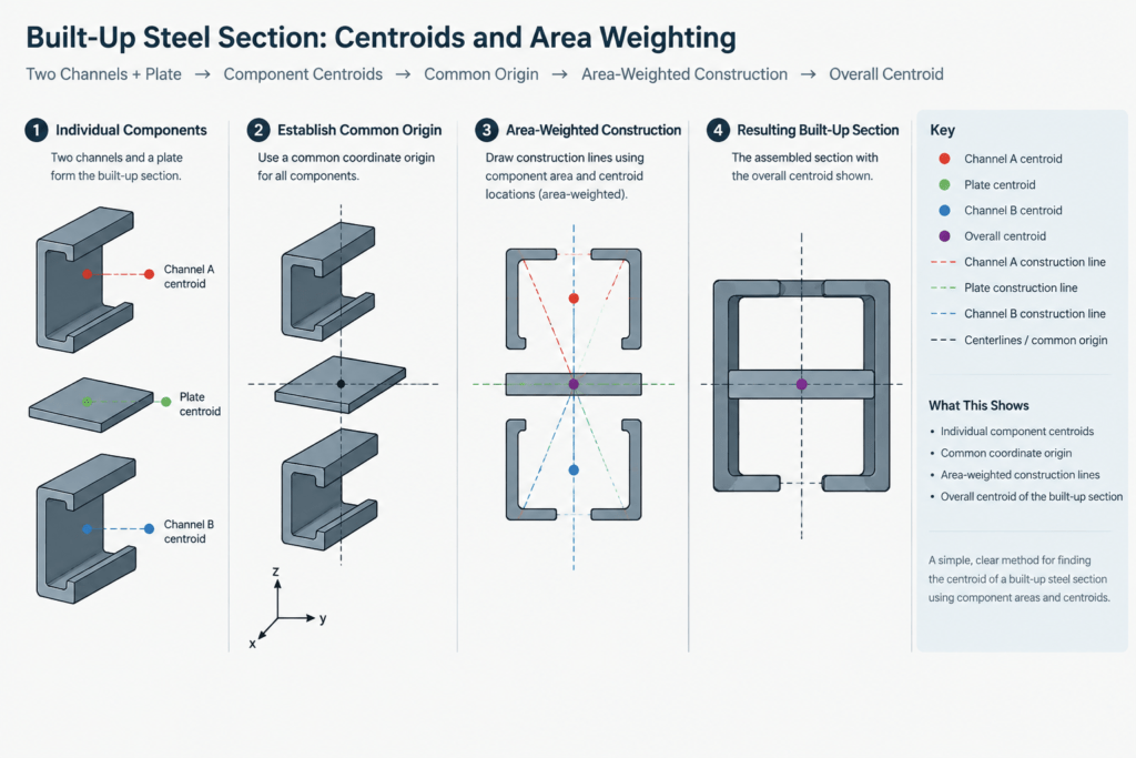
- Building a compound member from channels, angles, plates, or tees
- Comparing a CAD section origin with a structural analysis model insertion point
- Checking whether a load path passes through a centroid, shear center, or neither
An offset does not automatically mean a detail is incorrect. It means the force path and resulting effects may require evaluation by the responsible engineer. The detailer’s role is to preserve and communicate the intended geometry.
Centroids of Built-Up Sections
For a built-up section, the overall centroid is found by area-weighting the centroid of each component. Conceptually, the coordinate in either direction is the sum of each component area multiplied by its centroid coordinate, divided by the total area.
This method requires every component coordinate to use the same origin and axis directions. Plates, rolled shapes, and HSS components cannot be combined reliably if one coordinate is measured from a local face and another from a project centerline without first transforming them into a common system.
Voids and subtracted regions are handled as negative areas in an idealized geometric calculation. Weld metal, copes, holes, and other features should be included or excluded according to the purpose and precision of the model. A simplified detailing model and an engineering property calculation may reasonably use different levels of geometric detail.
A Practical CAD Workflow
- Confirm the designation. Verify the shape family and exact member designation before using any property.
- Identify the source convention. Review the diagram that defines x̄, ȳ, the origin, and axis directions.
- Inspect the CAD geometry. Determine whether the section is represented by nominal outlines, detailed fillets, or another approximation.
- Locate the local centroid. Place a temporary point or construction-line intersection using the verified coordinate convention.
- Transform the section. Rotate or mirror the shape into its required member orientation while keeping the centroid associated with the geometry.
- Place it in project coordinates. Apply the specified offset from grids, elevations, faces, work points, or connection lines.
- Check the result independently. Use symmetry, CAD area properties, or a separate calculation as a reasonableness check.
- Label reference lines clearly. Distinguish member centerlines, centroidal axes, work lines, and physical faces where ambiguity could affect fabrication or coordination.
Common Errors to Avoid
- Assuming the centroid is always at half the overall width and depth
- Using a table value without its defining section sketch
- Confusing a CAD block insertion point with the centroid
- Mirroring a channel or angle without reversing the applicable project-coordinate offset
- Swapping angle coordinates after rotation without tracking the local axes
- Treating centroid and shear center as interchangeable
- Recalculating from a sharp-corner outline and expecting exact agreement with rolled-shape properties
- Combining built-up components that use different origins
Final Reference Check
Before relying on steel shape centroid coordinates, confirm three things: the exact shape, the origin used by the property source, and the orientation of the section in the drawing. Then keep local section coordinates separate from project coordinates until the final placement transformation is made.
This approach prevents many avoidable CAD and detailing errors. It also makes offsets visible, allows section properties to be interpreted consistently, and improves coordination between shape tables, analytical models, and fabrication drawings.