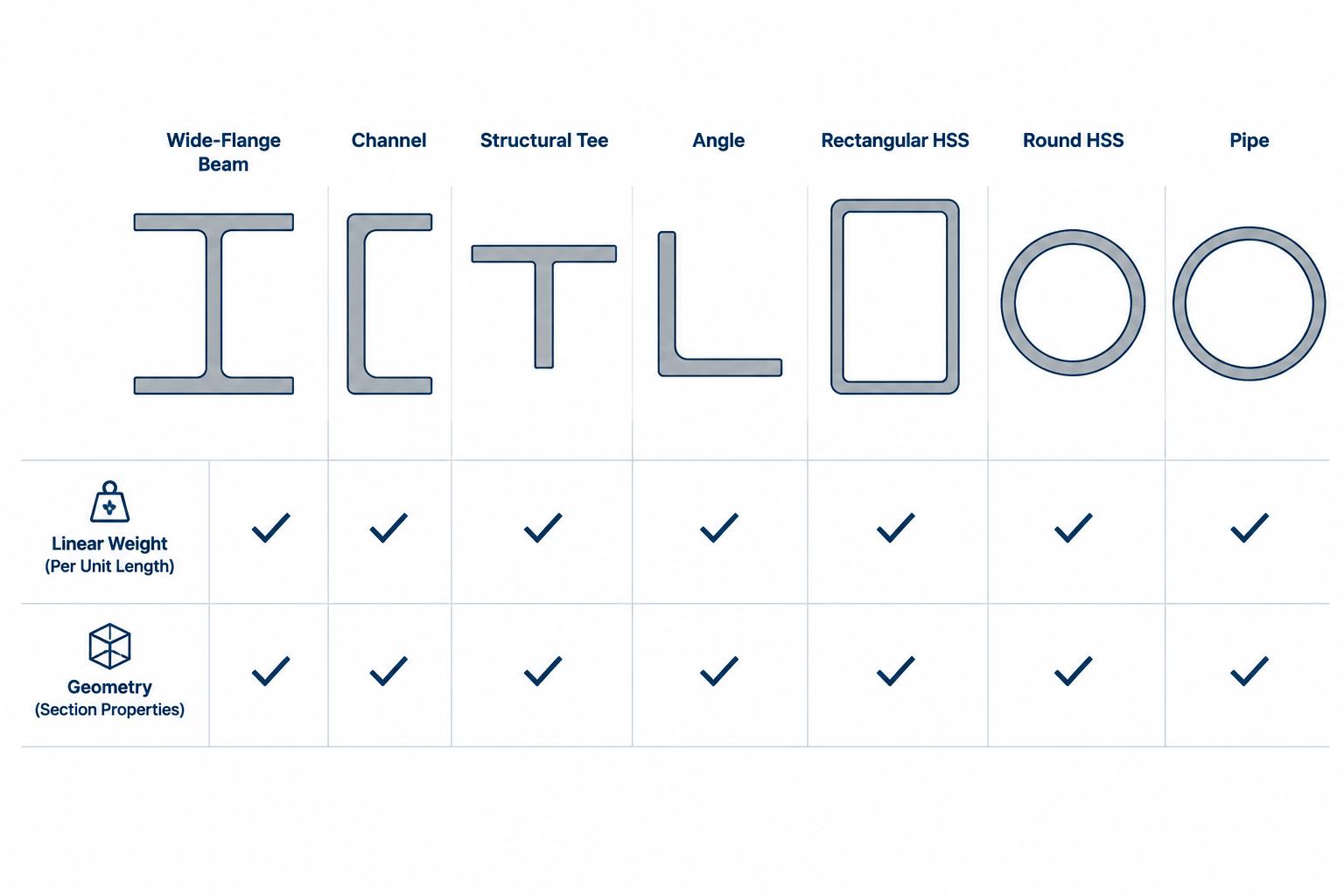
Tag: steel angles
-
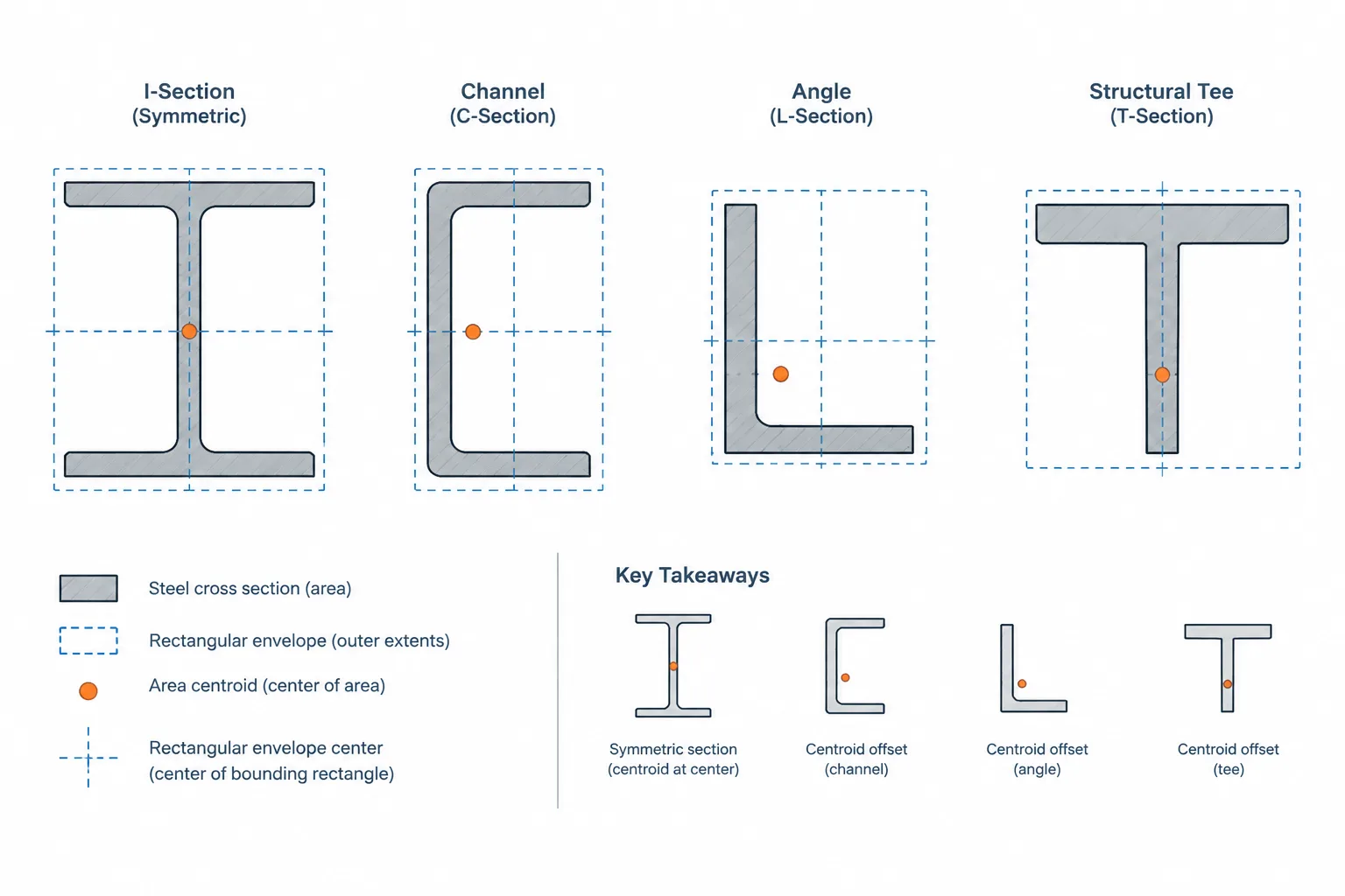
Centroid vs. Geometric Center in Structural Steel Shapes: Choosing the Correct Reference
Learn why a steel shape’s centroid may not match its overall geometric center and how that difference affects axes, dimensions, modeling, and detailing.
Written by
-
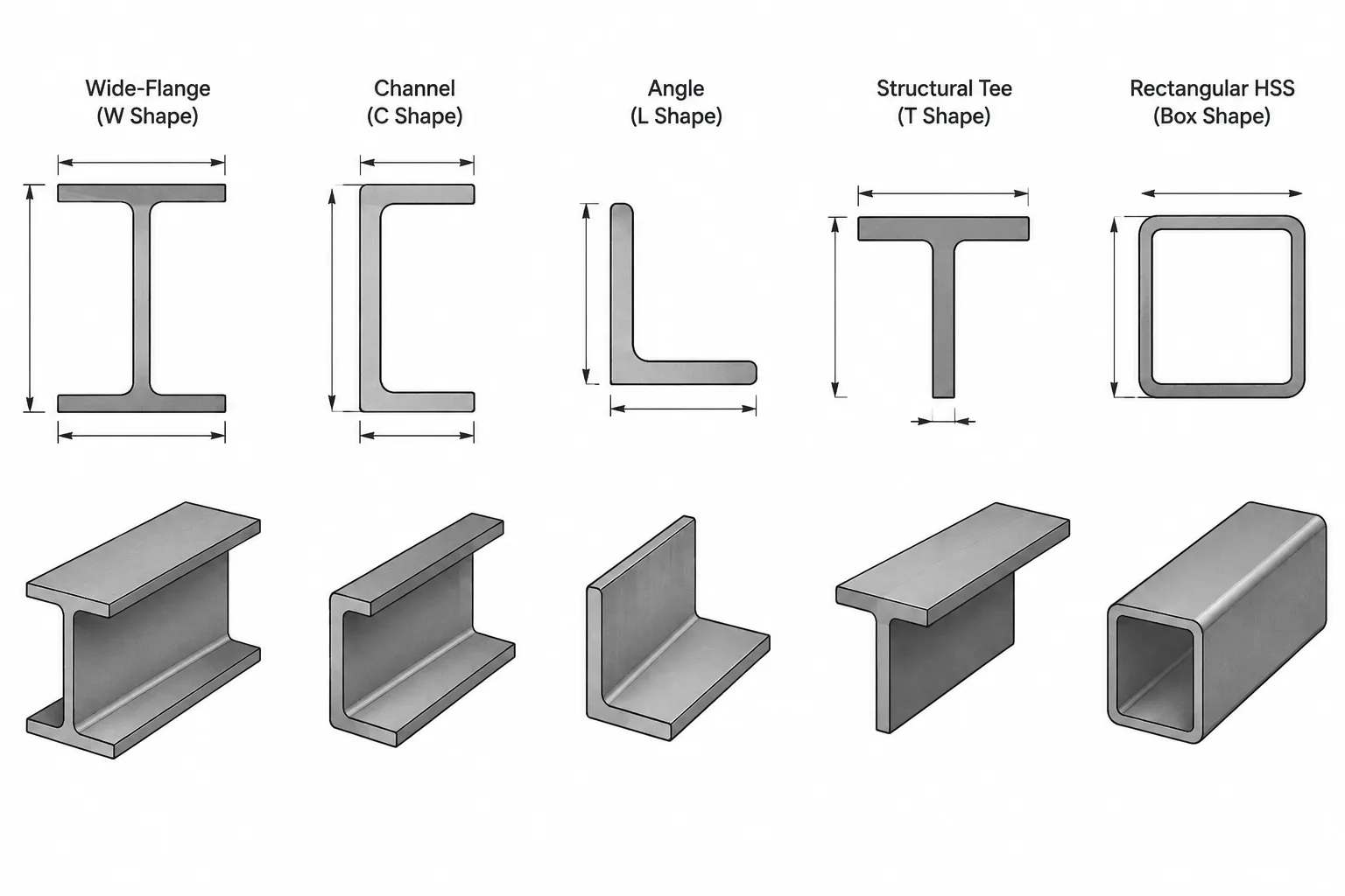
Steel Shape Designations vs. Tabulated Dimensions: What the Shape Name Does Not Tell You
Learn how W-shape, channel, angle, tee, HP, and HSS designations differ from tabulated dimensions, and which values should control CAD and detailing.
Written by
-
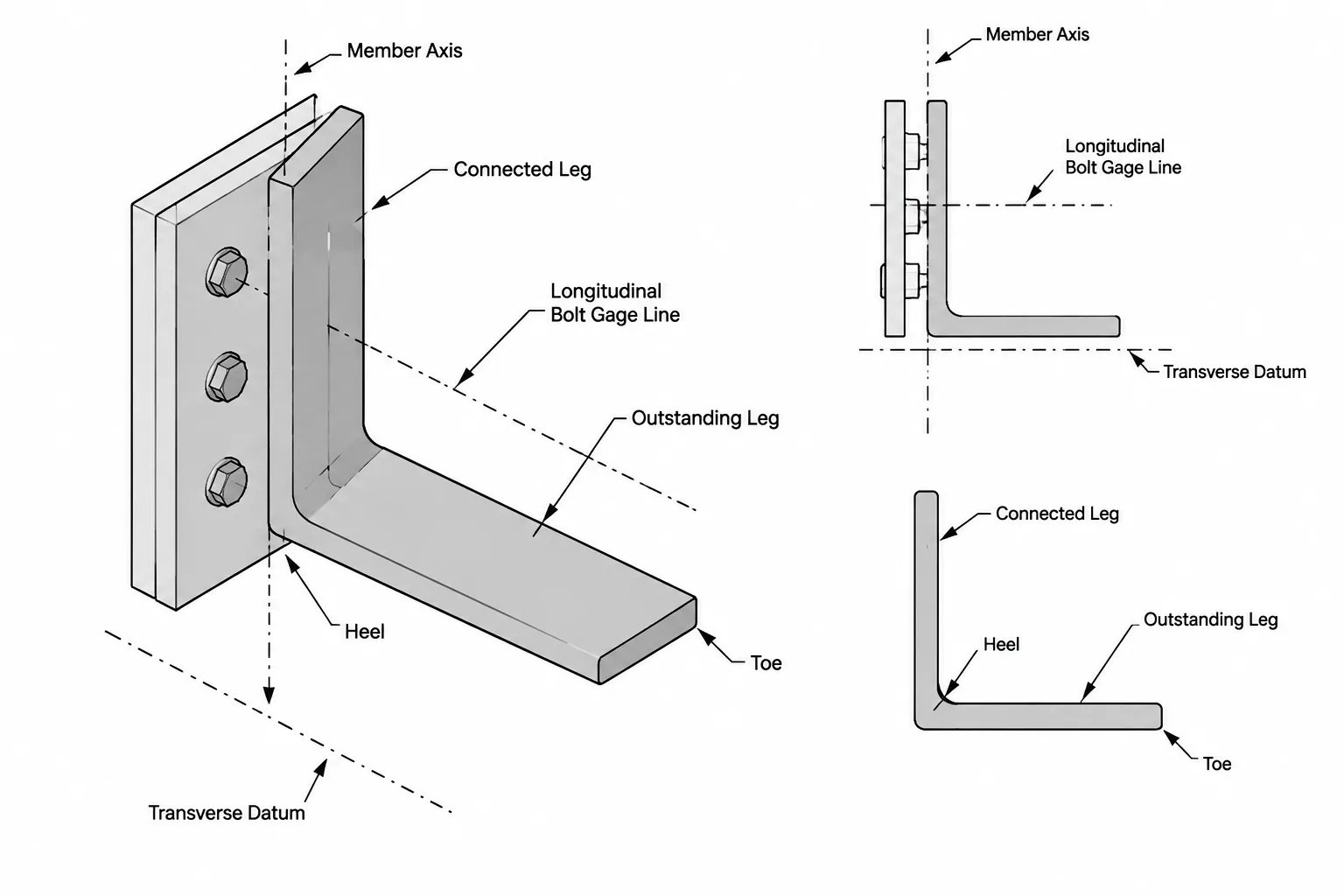
Steel Angle Bolt Gage: Heel, Toe, Leg Orientation, and Hole Layout
Learn how steel angle bolt gage relates to the heel, toe, connected leg, hole lines, edge clearance, and reliable shop drawing dimensions.
Written by
-
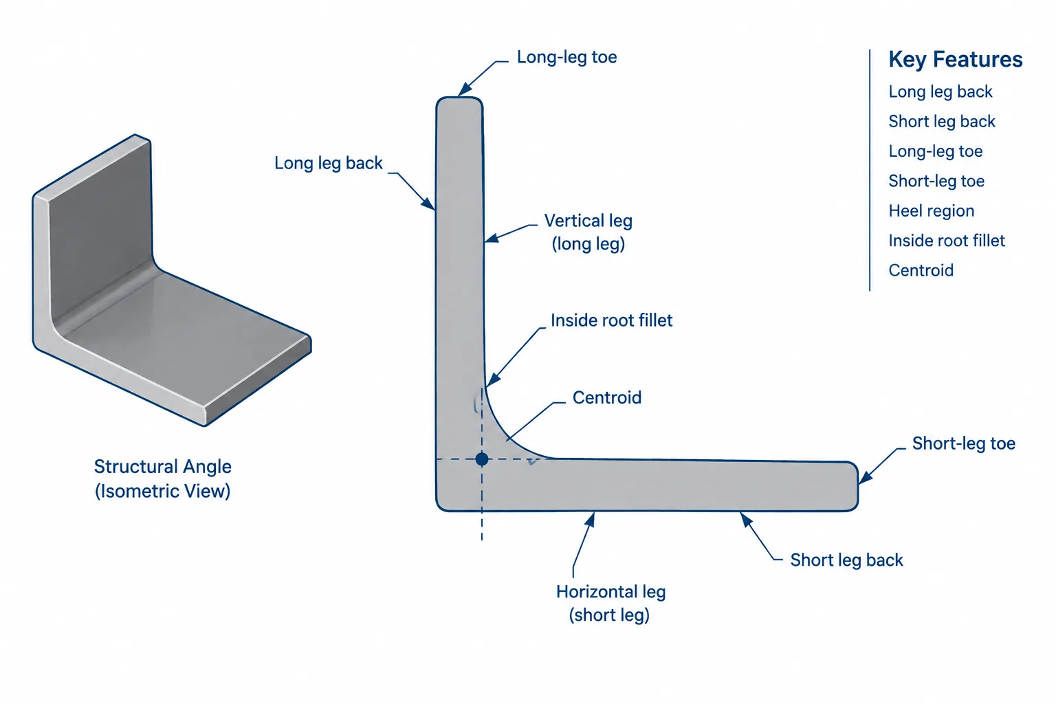
Steel Angle Heel, Toe, and Root Radius: Geometry, Datums, and CAD Detailing
Learn steel angle heel, toe, root-radius, back-of-leg, and centroid terminology for clearer drawings, connection layouts, and CAD shape models.
Written by
-
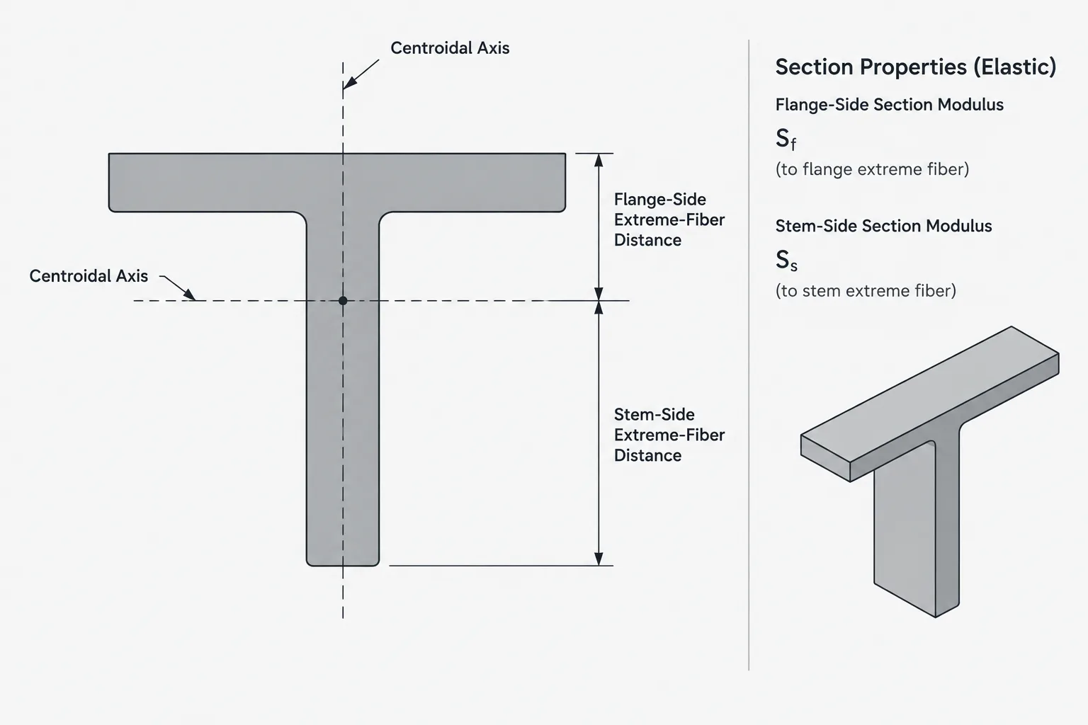
Elastic Section Modulus for Unsymmetric Steel Shapes: Why Each Side Can Have a Different S
Learn why channels, tees, and angles can have different elastic section moduli on opposite sides of an axis and how to verify them in shape tables and CAD.
Written by
-
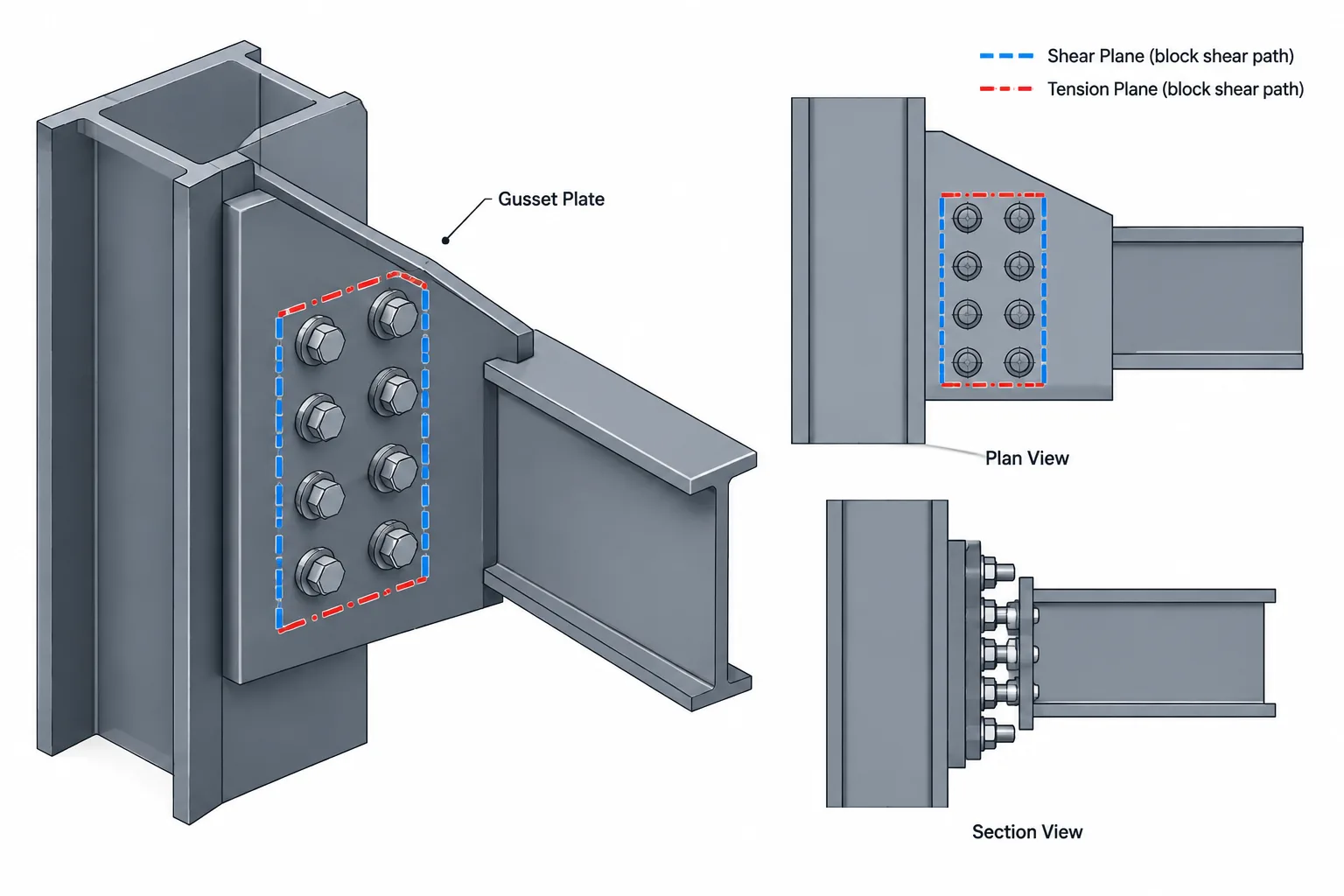
Block Shear Paths in Steel Connections: A Practical Guide to Plates, Angles, Tees, and Gussets
Learn how to identify block shear paths around bolt groups in steel plates, angles, tees, and gussets, including tension planes, shear planes, and CAD checks.
Written by
-
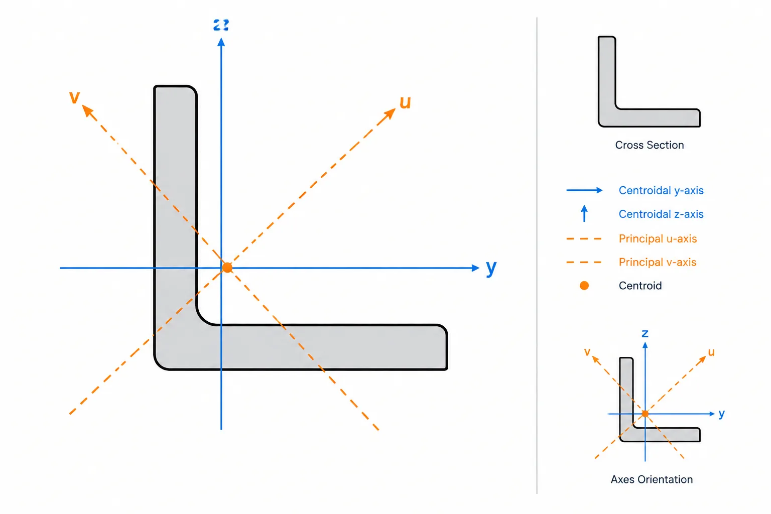
Product of Inertia Ixy in Steel Sections: Unsymmetric Bending and Principal Axes
Learn what product of inertia Ixy means for steel sections, why it matters for angles and built-up members, and how to verify axes and CAD properties.
Written by
-
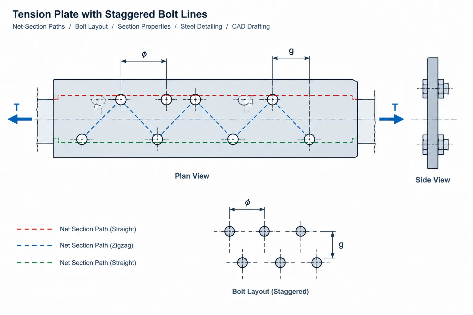
Staggered Bolt Holes and Net-Section Paths in Steel Plates and Angles
Learn how staggered bolt holes affect net-section paths in steel plates and angles, including pitch, gage, diagonal paths, CAD checks, and common detailing errors.
Written by
-
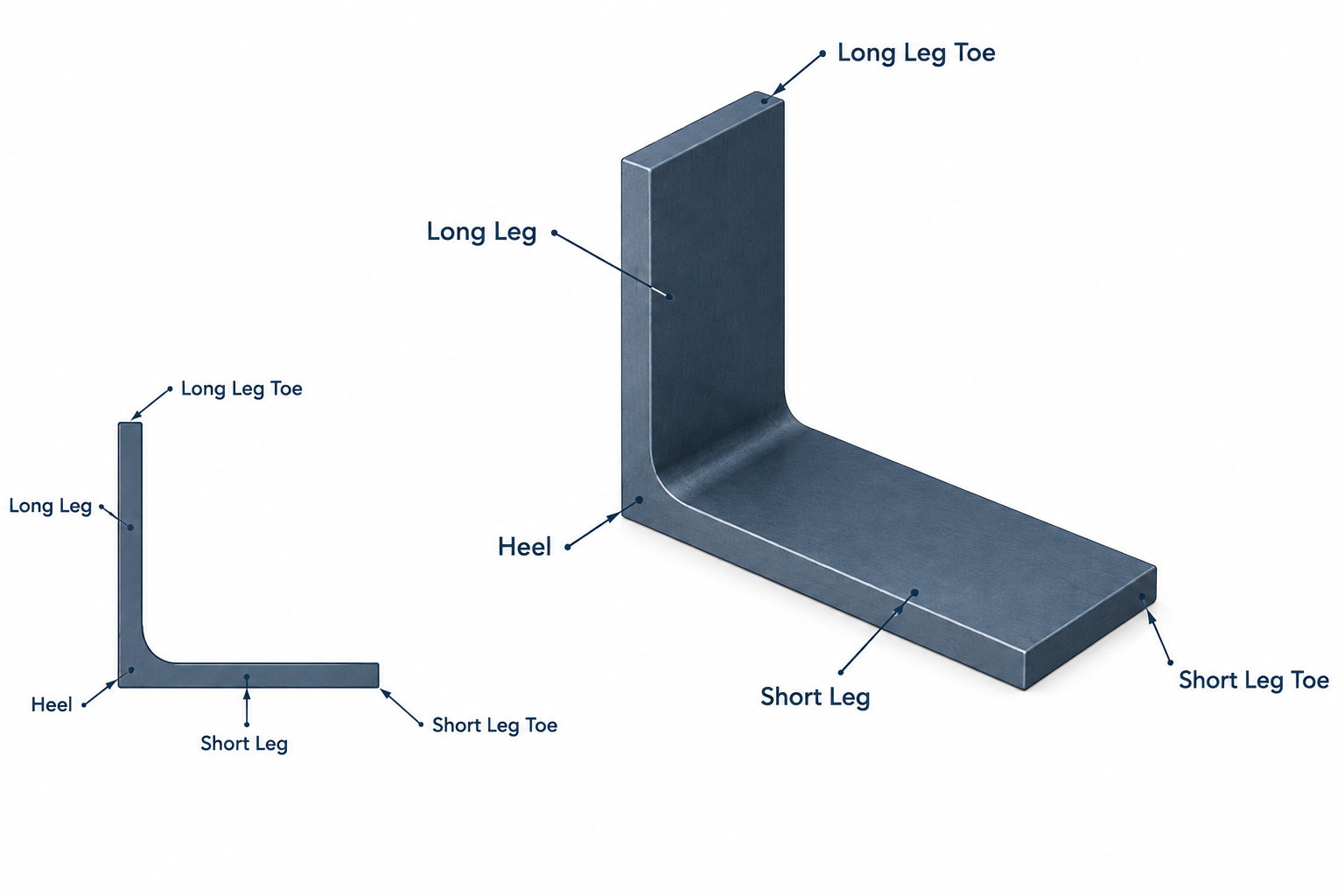
Steel Angle Orientation: LLV, SLV, Connected Legs, and Drawing Clarity
Learn how to communicate steel angle orientation using LLV, SLV, heel, toe, connected-leg, and view-specific detailing conventions.
Written by
-
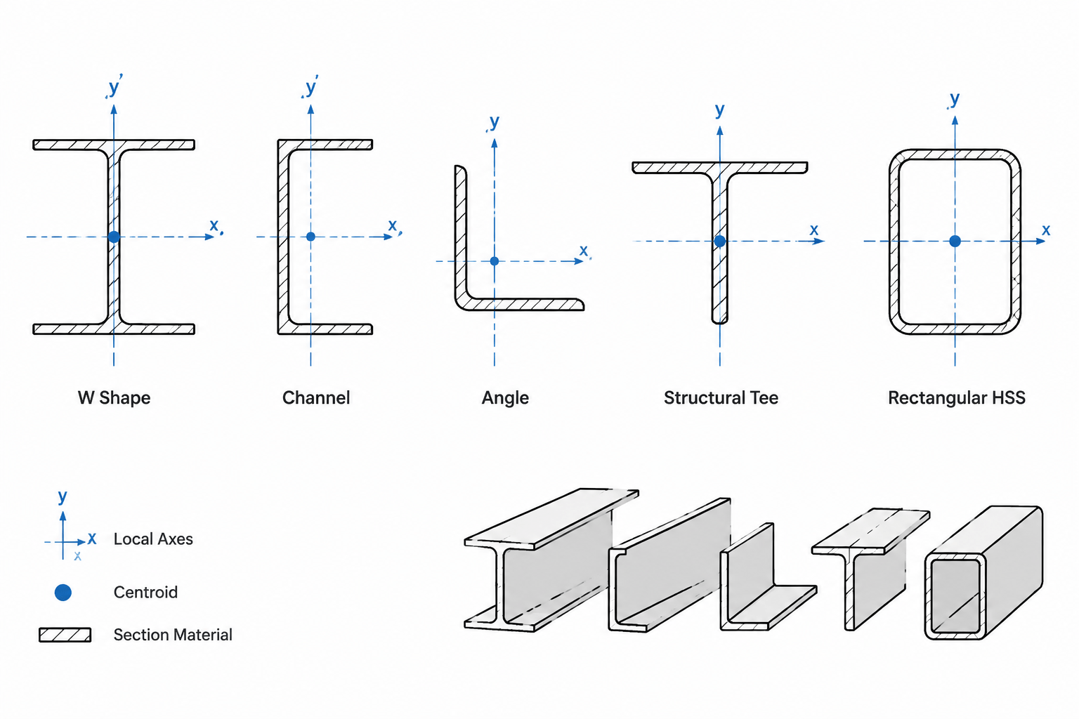
Centroid Coordinates in Steel Shape Tables: x̄, ȳ, Reference Axes, and CAD Placement
Learn how to interpret x-bar and y-bar centroid coordinates for W shapes, channels, angles, tees, and HSS, including reference origins and CAD checks.
Written by
-
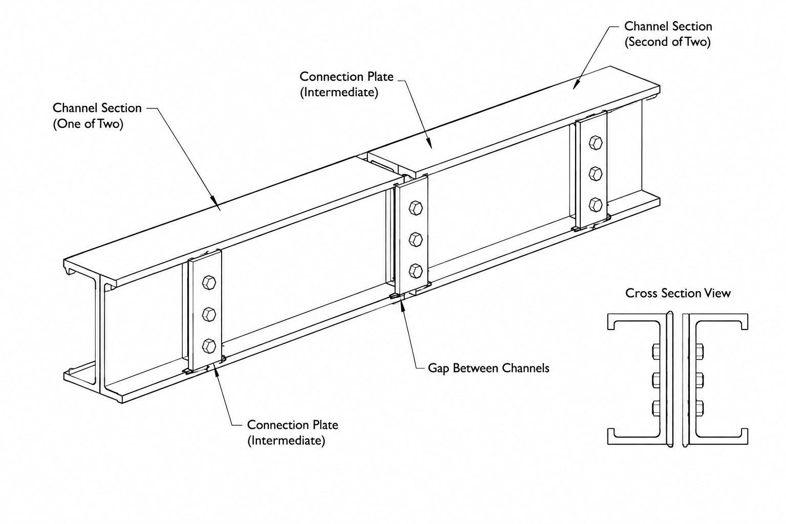
Back-to-Back Steel Channels and Angles: Orientation, Spacing, and Detailing
Learn how to detail back-to-back steel channels and angles, including orientation, spacing, built-up behavior, section properties, and CAD drawing practice.
Written by
-
Reading Steel Shape Designations: Where Weight per Foot Appears—and Where It Does Not
Learn which structural steel designations include nominal weight per foot, which describe geometry instead, and how to estimate member weight correctly.
Written by