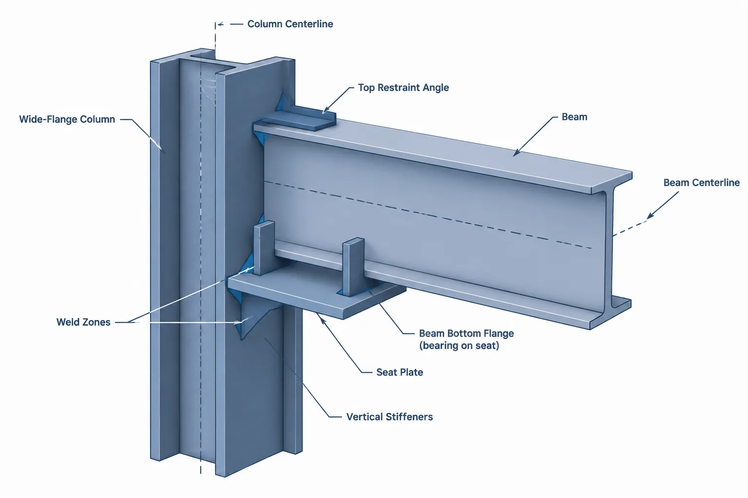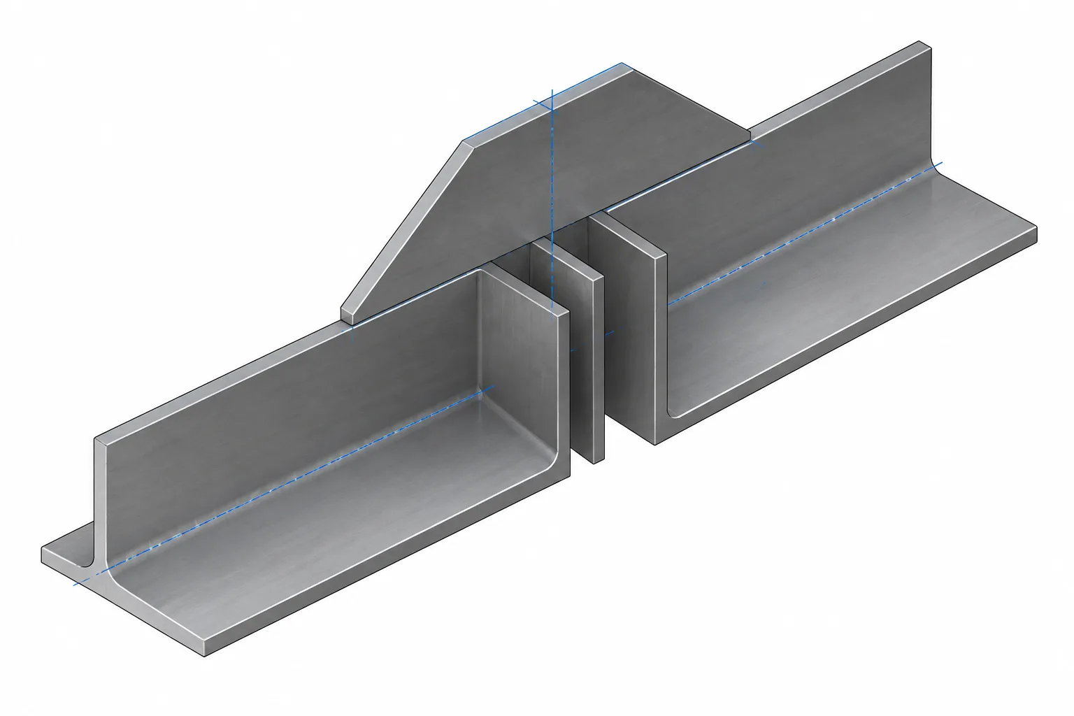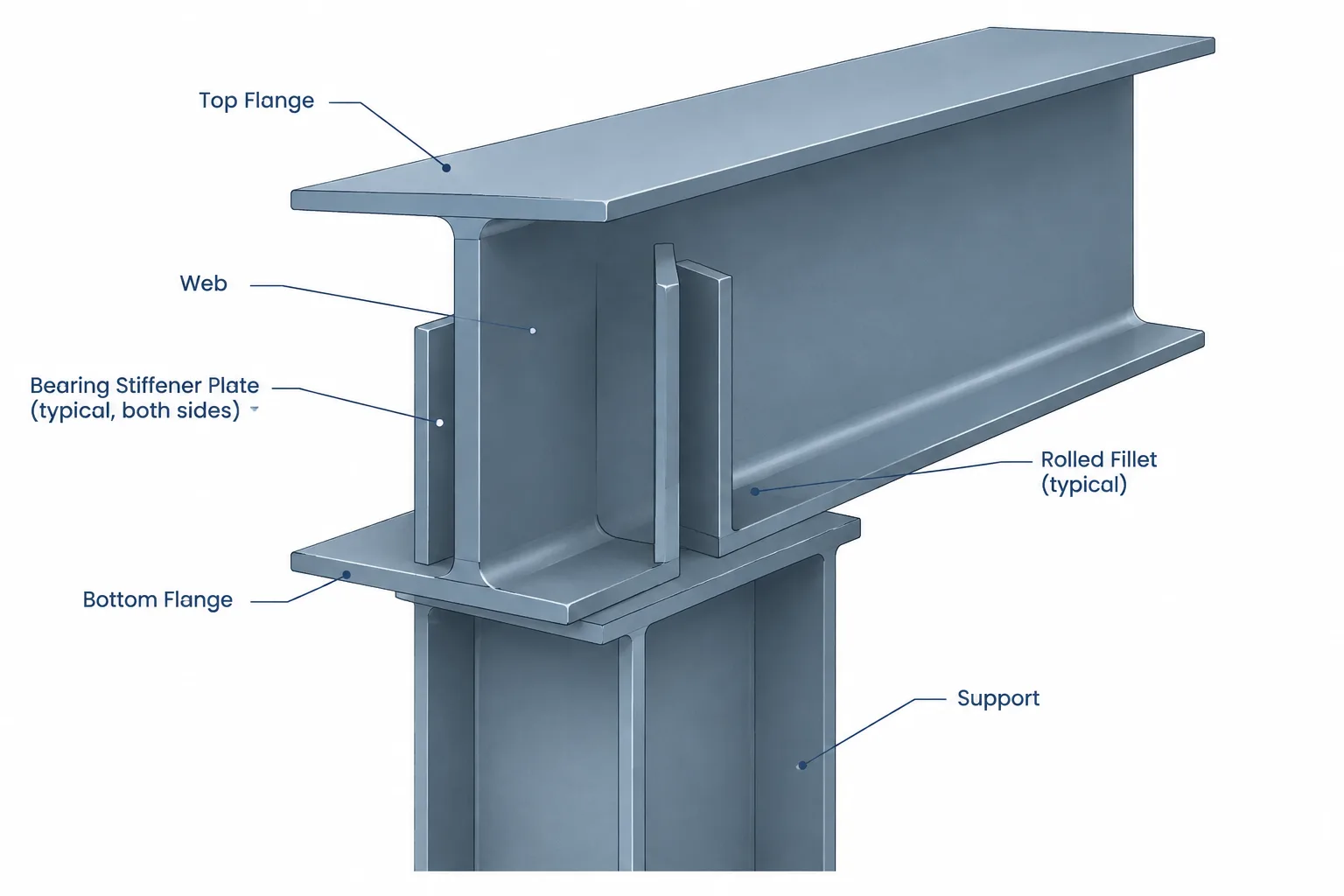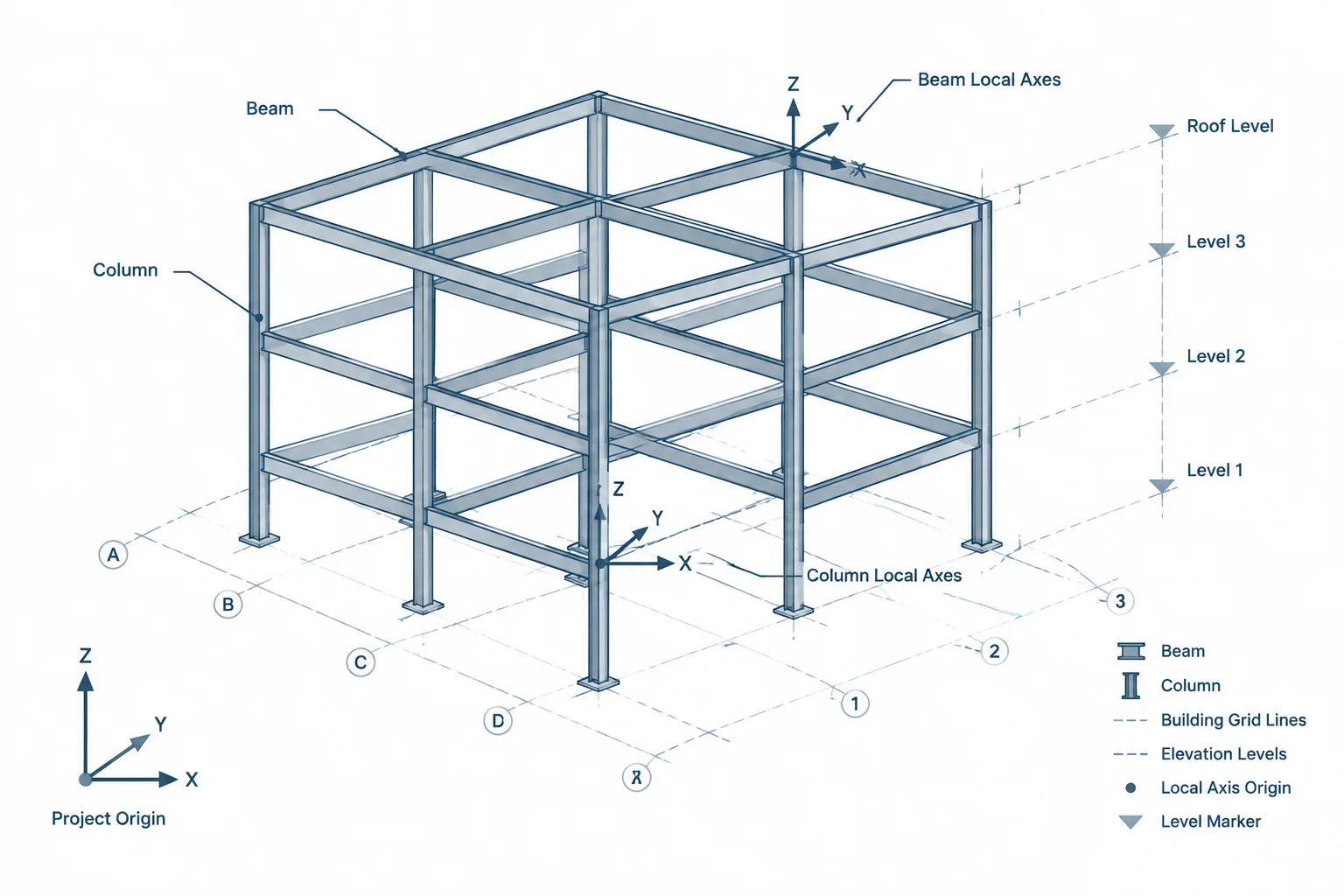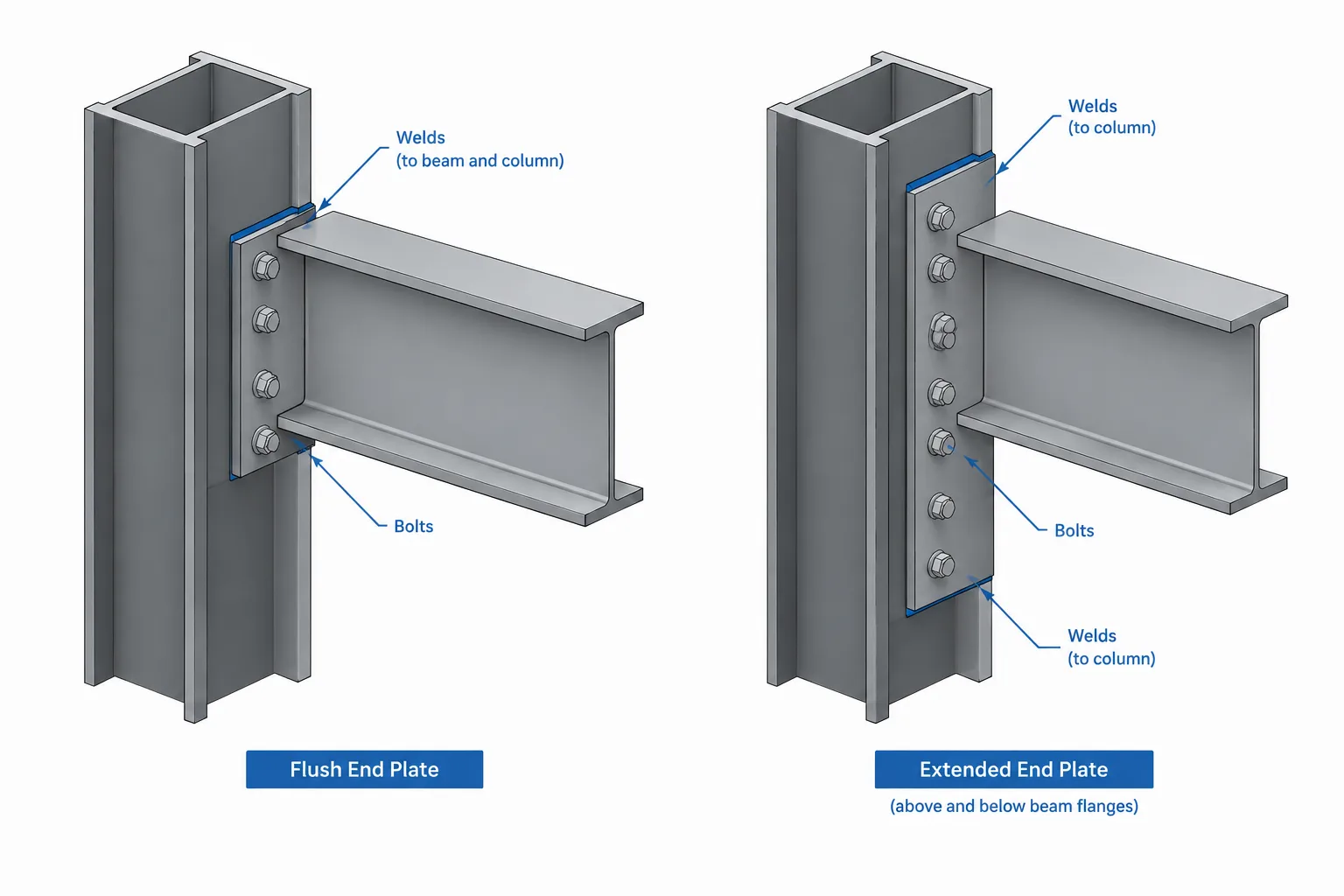
A bolted steel connection may contain holes in a beam web, connection plate, clip angle, gusset, splice plate, or supporting member. Each part can look correct when checked separately, yet the holes may still fail to align when the parts are assembled. The usual cause is not a single incorrect hole coordinate. It is a coordination problem involving datums, orientation, accumulated variation, and the relationship between shop and field assembly.
Reliable multi-ply bolt hole alignment begins by treating the entire connection as one coordinated geometric system. The drawings and models must establish which point, line, face, or work point controls the hole group in every connected part.
What Is a Multi-Ply Bolted Connection?
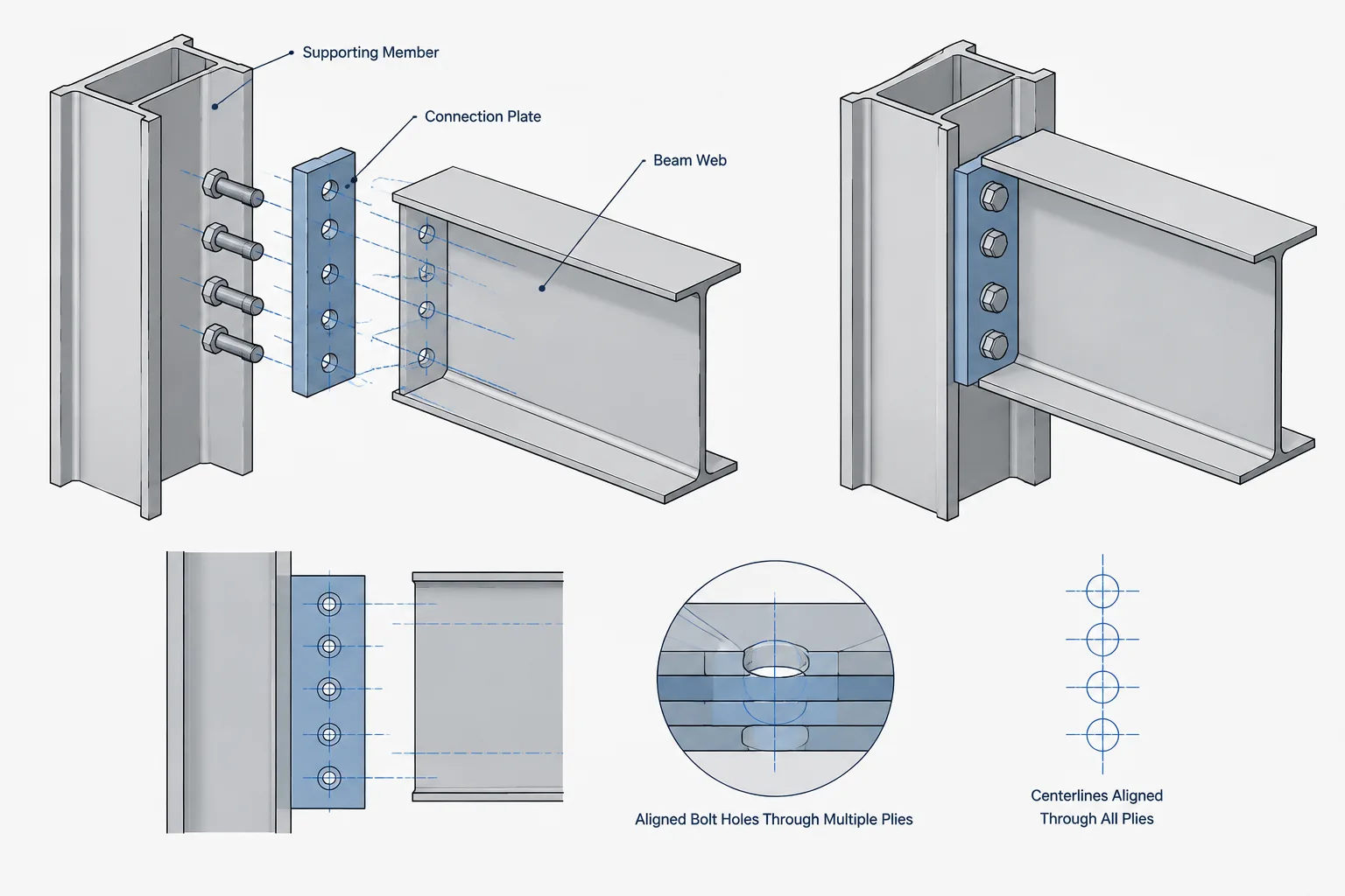
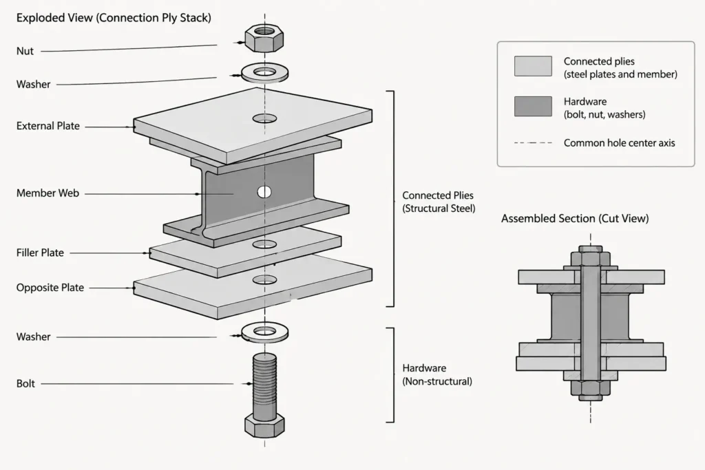
A ply is one layer of material through which a bolt passes. A simple lap joint has two plies. More complex connections can include a main member, plates on one or both sides, fillers, reinforcing material, or multiple outstanding legs. Although washers are part of the installed bolt assembly, they are not normally treated as connected plies when laying out the structural hole group.
Common multi-ply arrangements include:
- A beam web connected to a shear plate.
- Two splice plates attached to opposite sides of a web.
- A gusset plate between paired angles or other connection elements.
- A web with reinforcing plates and external connection material.
- Overlapping plates in a bracing, truss, or built-up member connection.
- Connection angles linking one member to another through separate legs.
For the bolt to pass through the assembly, corresponding holes need compatible center locations in the plane of each ply. This requirement sounds simple, but each part may be detailed from a different face, edge, centerline, or member end.
Hole Alignment Is More Than Matching Spacing
Two parts can show the same pitch and gage while their complete hole patterns remain misaligned. Spacing describes the relationship between holes within a group. It does not establish where the group sits on the part.
A coordinated hole group requires agreement in several areas:
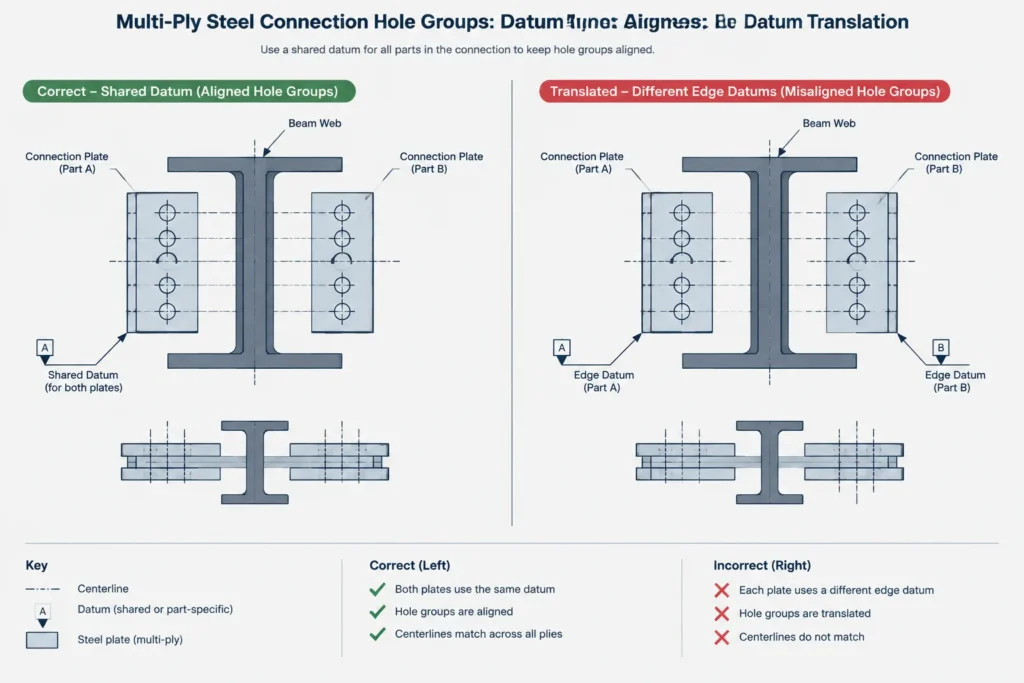
- Pattern geometry: The number of rows and lines, their spacing, and any stagger must correspond.
- Group location: The pattern must be positioned from compatible controlling datums.
- Orientation: The group cannot be unintentionally mirrored, rotated, or placed on the wrong face.
- Ply order: Fillers, reinforcement, and plates must appear in the intended stack.
- Member position: End setbacks, top-of-steel relationships, slopes, and connection offsets must be consistent.
A CAD comparison that checks only center-to-center spacing may therefore miss a translated or mirrored pattern.
Selecting a Common Datum
The best datum is generally the feature that most directly controls assembly. Depending on the connection, that may be a member work point, beam end, column centerline, top-of-steel line, plate edge, web centerline, or connection centerline.
Every connected part does not have to use identical dimensions on its shop drawing. However, those dimensions must resolve to the same physical hole-center coordinates after member placement and orientation are considered.
Member-Based Datums
Member-based datums are useful when the connection location is controlled by framing geometry. A beam-end hole group, for example, may be located longitudinally from the detailed end and vertically from top of steel or another established member reference.
This approach requires a clear distinction between the work-point length, detailed member length, and actual cut end. If one part is located from a work point while another is located from the cut end, any setback between those references must be included.
Part-Based Datums
Part-based dimensions locate holes from plate or angle edges. They are convenient for fabrication, inspection, and CNC data creation. Their success depends on the part edges being correctly related to the connection datum.
For example, a plate may have a fully consistent hole pattern measured from its lower-left corner but still fail to match the member if the plate outline, edge reference, or placement offset is wrong.
Centerline Datums
A pattern centered on a web, plate, or connection work line can reduce ambiguity. Centerline control is especially useful for symmetric groups. The drawing should still make clear whether the centerline refers to the member, web, plate, bolt group, or supporting element. These lines often coincide in a simple detail but should not be assumed to coincide in every connection.
How Stack-Up Affects Alignment
Stack-up is the combined effect of geometry and variation across the assembly. It is not limited to the total grip through the connected material. In hole alignment work, stack-up also includes the chain of dimensions that determines where each hole arrives relative to the others.
| Stack-up source | Possible result | Coordination response |
|---|---|---|
| Different part datums | Complete pattern translated from its intended location | Resolve every pattern to a shared connection coordinate system |
| Chained edge dimensions | Variation accumulates toward the final row | Use a stable baseline or ordinate strategy where appropriate |
| Member end setback | Plate holes match the work point but not the fabricated end condition | Show the relationship among work point, setback, and cut end |
| Opposite-side plate modeling | Asymmetric pattern is unintentionally mirrored | Check the assembly from a fixed viewing direction |
| Sloped or skewed member | Projected dimensions replace true in-plane coordinates | Lay out the holes in the actual connection plane |
| Added filler or reinforcement | Ply order or required bolt grip changes | Update sections, material lists, and bolt information together |
Variation cannot be eliminated merely by making a CAD model exact. The model establishes design intent, while fabrication and erection involve real material and processes. Good detailing avoids consuming available fit-up allowance through preventable coordinate errors.
Orientation and Mirroring Errors
Asymmetric patterns deserve special attention. A staggered group, unequal edge distances, offset gage, or nonrectangular plate can appear correct when viewed from either side, even though one part has been mirrored incorrectly.
Near-side and far-side plates can also create confusion. Copying geometry to the opposite side of a web is not always equivalent to mirroring the manufactured part. The correct operation depends on whether the plate itself is handed, whether the hole group is symmetric, and which face is used as the fabrication reference.
A useful check is to assign a consistent member direction and viewing convention. Then compare each ply as it appears in the assembled connection, not merely as an isolated part displayed face-up.
CAD and Model Checks for Corresponding Holes
Hole alignment checks should use hole centers rather than visible circle edges. The center points represent the layout coordinates and remain useful when hole types or displayed diameters differ.
A practical digital review can include the following steps:
- Confirm the member work lines, ends, offsets, and section orientations.
- Identify the controlling connection plane and datum.
- Extract or display the center points for each hole group.
- Transform all connected parts into their assembled positions.
- Compare corresponding centers along the connection plane.
- Inspect asymmetric patterns for mirroring or rotation.
- Review a section through the complete ply stack.
- Confirm that the drawings, model, bill of material, and fabrication data describe the same revision.
Automated clash tools may not detect a small coordinate mismatch, particularly when modeled holes overlap partially. A dedicated center-coordinate comparison is often more informative than a visual review of shaded solids.
Hole Type Is Not a Substitute for Coordination
Oversized or slotted holes may be intentionally specified for particular connection behavior, installation needs, or adjustment. They should not be introduced simply to conceal a detailing error. Hole type, slot direction, washers, and connection behavior are related engineering and fabrication decisions.
Likewise, field modification should not be assumed to be an acceptable correction for mismatched holes. Any proposed reaming, enlargement, slotting, welding repair, or replacement requires review through the project’s established approval process.
What the Drawings Should Communicate
Clear drawings help the shop and field identify both the pattern and its controlling location. Depending on the connection, useful information may include:
- A clearly identified connection or member datum.
- Baseline or ordinate dimensions to hole centers.
- Pitch, gage, stagger, and row relationships without redundant conflicts.
- Member-end setbacks and plate placement dimensions.
- Near-side, far-side, or viewing-direction information.
- Sections showing the complete ply order.
- Identification of fillers, reinforcement, or pack material.
- Consistent hole and bolt information across assembly and part drawings.
- Handed-part or match-mark information when geometry is not interchangeable.
Dimensions should be complete enough to fabricate and inspect the parts, but unnecessary duplicate dimensions can create competing controls. If the same hole center is located in several ways, revisions may update one dimension while leaving another unchanged.
A Practical Alignment Review Checklist
- Do all plies reference the same physical connection location?
- Are member ends, work points, and setbacks distinguished?
- Are corresponding holes compared by center coordinate?
- Has the full pattern been checked for translation, rotation, and mirroring?
- Are slope and skew handled in the true connection plane?
- Does the section show every connected ply in the correct order?
- Are opposite-side plates genuinely interchangeable, or are they handed?
- Do assembly drawings, part drawings, and digital fabrication data share the same revision?
- Have connection changes been carried through to bolt grip and material information?
- Are proposed fit-up changes routed for the required technical review?
Coordinate the Assembly, Not Just the Parts
Successful multi-ply bolt hole alignment depends on more than accurate hole spacing. The detailer must connect member geometry, part geometry, assembly orientation, and fabrication data through a stable set of datums.
The most reliable workflow is to establish the connection coordinate system first, resolve every hole center back to that system, and then verify the full stack in assembled position. This approach catches the translated plate, mirrored pattern, omitted setback, and misplaced filler before they become shop or field problems.