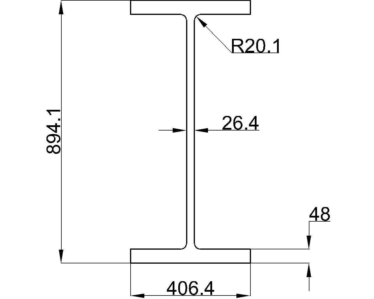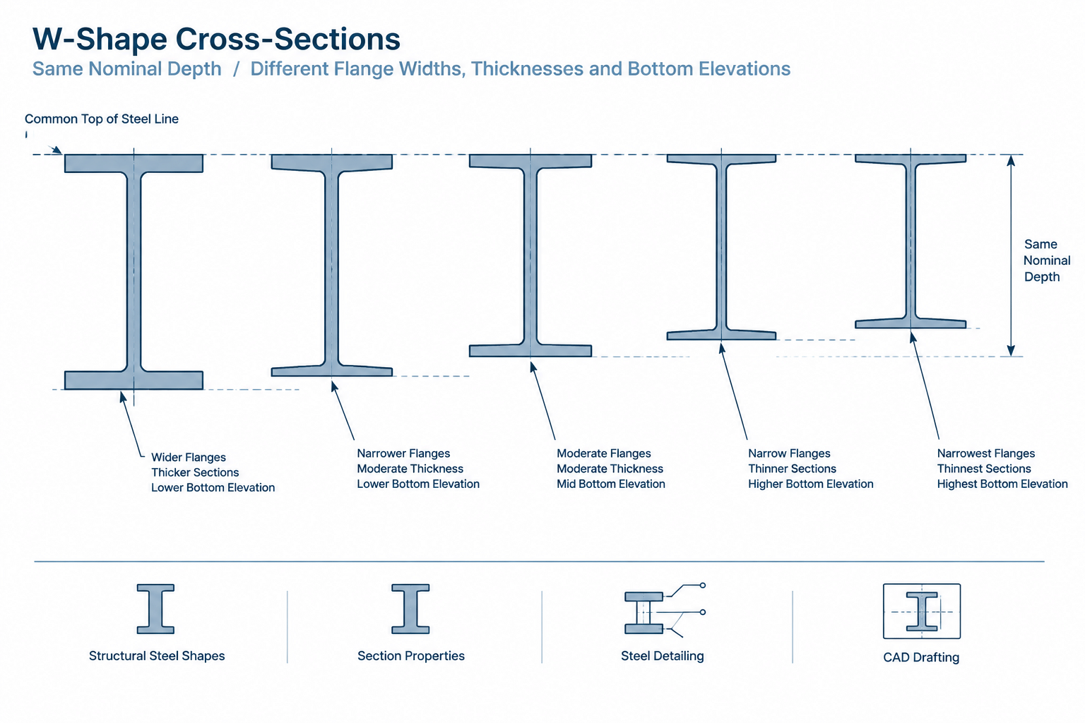
A W-shape designation organizes rolled sections into a recognizable family, but it is not a complete geometric description. Two members from the same nominal depth series may have different actual depths, flange widths, flange thicknesses, web thicknesses, fillet regions, and section properties. As a result, replacing one shape with another from the same series can change elevations, connection geometry, clearances, and CAD alignment.
This distinction matters whenever a drafter, designer, or fabricator expects related W-shapes to line up automatically. The family name is useful for identification, but verified table dimensions—not the nominal series alone—must control the model and detail.
Nominal depth is a classification, not a guaranteed dimension
In a customary W-shape designation, the first part identifies a nominal depth series. The second part identifies nominal weight per unit length. Neither part provides all dimensions required to draw the cross-section accurately.
The actual overall depth is normally listed separately as d in a shape table. That value should be used when establishing the physical top and bottom surfaces of the member. It should not be assumed that every section carrying the same nominal depth label has an identical d value.
This is similar to other nominal construction terms: the name helps classify the product, while the detailed dimensional data defines its geometry. The designation remains essential for communication, but it is not a substitute for the shape record.
Why shapes within one series can differ
W-shapes in a common series are not created by simply increasing every plate-like element while holding the outer envelope fixed. Rolled-shape geometry reflects available production profiles and the combinations of web and flange material needed to produce different weights and section properties.
Moving from one shape to another can therefore change several dimensions at once:
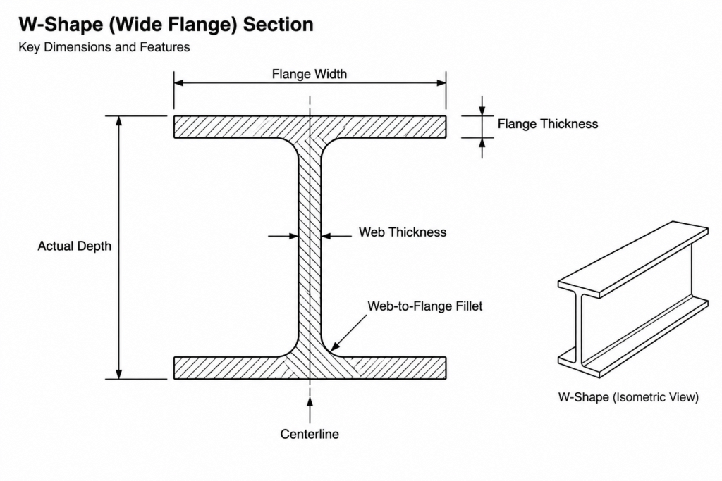
- Overall depth: The actual distance from the outside of one flange to the outside of the other may change.
- Flange width: The width across the flanges may not remain constant throughout a series.
- Flange thickness: A different flange thickness changes the location of the inside flange faces even when the outside face is held at a common elevation.
- Web thickness: This affects connection fit, weld access, bolt layouts, and the position of attached material relative to the member center plane.
- Fillet or k-region geometry: The transition between web and flange affects usable web area and clearance for plates, welds, bolts, and coping.
The direction or amount of change should not be predicted from the designation alone. Dimensions must be checked for the specific shape under consideration.
Which dimensions should be compared?
When evaluating two W-shapes from the same nominal series, compare the dimensional fields that affect both the member envelope and its connections. Symbols can vary among references, but the following concepts are commonly included in structural shape data.
| Dimension or property | Typical symbol | Why it matters |
|---|---|---|
| Actual overall depth | d | Controls outside flange locations, member envelope, and elevation relationships. |
| Flange width | bf | Affects plan width, edge clearances, framing conflicts, and flange attachments. |
| Flange thickness | tf | Controls inside flange-face location and influences connection clearances. |
| Web thickness | tw | Affects web attachments, weld geometry, and the position of connection plates. |
| Web-to-flange transition | k-related dimensions | Defines regions where connection material or welds may conflict with rolled fillets. |
| Cross-sectional area | A | Useful for weight and design checks, but it does not define the shape envelope. |
Section properties such as moment of inertia, section modulus, and radius of gyration must also be checked for engineering evaluation. However, equal nominal depth does not imply equal properties, just as it does not imply equal geometry.
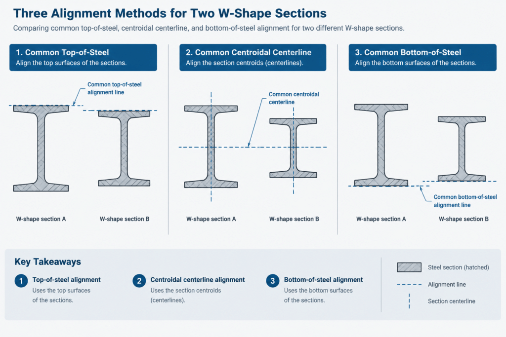
Alignment depends on the controlling reference
Whether two W-shapes appear to line up depends on how they are positioned. A model must distinguish between the analytical or geometric member line and the physical steel surfaces.
Top-of-steel alignment
If two beams are placed with their top flange surfaces at the same elevation, differences in actual depth appear at the bottom of the members. Their bottom-of-steel elevations may not match. Their centroidal axes may also occur at different elevations relative to the shared top surface.
This arrangement is often relevant where floor framing, deck support, or another architectural elevation controls the top surface. It should still be confirmed from the project drawings rather than assumed.
Centerline alignment
If the member centerlines are aligned, differences in actual depth are divided around that reference for doubly symmetric W-shapes. The top and bottom flange surfaces can then occur at different elevations. This may be convenient for analytical modeling but unsuitable as an automatic detailing rule.
Bottom-of-steel alignment
When a lower clearance plane controls, members may be positioned from their bottom surfaces. Any depth difference then appears at the top. This can affect framing elevations and attached construction above the steel.
The key drafting question is therefore not simply, “Are these shapes in the same series?” It is, “Which physical surface or reference line is required to align?”
How same-series substitutions affect connections
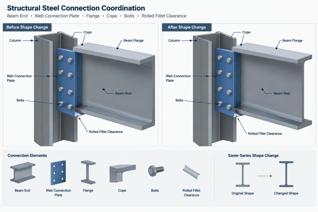
A proposed substitution within a nominal depth series should not be treated as a text-only revision. Even when the new member appears close in size, connection geometry may require review.
- Shear plates and angles: Changes in web thickness and fillet boundaries can alter fit, gage location, weld access, and available clear web depth.
- Beam copes: A cope based on the original flange thickness or transition geometry may not clear the revised supporting member.
- End plates: Bolt rows, plate edges, welds, and flange clearances depend on actual geometry rather than the nominal series name.
- Flange connections: A change in flange width or thickness can affect plate width, weld configuration, bolt layout, and interference with nearby parts.
- Stiffeners and doubler plates: Parts fitted between flanges must be checked against the actual inside-flange spacing and rolled transition regions.
- Adjacent construction: Deck edges, slab recesses, cladding supports, piping, and ceilings may be coordinated to a steel surface that moves when the shape changes.
Engineering adequacy and connection design must be verified by the responsible project professionals. Geometric similarity by itself does not establish that one member is an acceptable substitute for another.
A reliable CAD and detailing workflow
A controlled workflow reduces errors caused by nominal-depth assumptions.
- Read the complete designation. Confirm the exact shape rather than selecting the first block or profile from the correct nominal family.
- Retrieve verified dimensions. Use a reliable shape table or controlled database record for the specific member.
- Confirm insertion logic. Determine whether the CAD object is inserted at its centroid, web centerline, top of steel, bottom of steel, or another defined point.
- Place the member from the project reference. Use the required work line and elevation instead of visually aligning similar outlines.
- Regenerate the physical profile. If the shape changes, update the section geometry rather than editing only the member label.
- Recheck attached parts. Review connection plates, bolts, welds, copes, stiffeners, holes, and clearances.
- Review dependent views. A revision in a model or section should be reflected in plans, elevations, details, bills of material, and exported fabrication data.
CAD blocks and parametric profiles should also identify their origin and units. A block named only by nominal series is not sufficiently specific for dimensional detailing.
Do not scale a nearby W-shape profile
Uniformly scaling one W-shape outline to represent another is not a valid way to create section geometry. The web, flanges, fillets, and overall envelope do not necessarily change in a common proportion. Scaling can produce a profile that resembles a W-shape but matches no published section.
The safer method is to build or select the profile from verified dimensions for the exact designation. Simplified outlines may be appropriate for diagrammatic drawings, but they should be clearly separated from dimensionally controlled fabrication or coordination geometry.
Practical review checklist
Before accepting a same-series member change, verify the following:
- The exact old and new designations are documented.
- Actual depth, flange width, flange thickness, and web thickness have been compared.
- The controlling top, centerline, or bottom reference is identified.
- Fillet and connection-clearance regions have been reviewed.
- Attached plates, holes, bolts, welds, copes, and stiffeners have been updated as needed.
- Adjacent structural and nonstructural elements have been checked for interference.
- Required engineering review and project authorization have been completed.
A W-shape nominal depth is valuable for organizing and recognizing sections, but it does not guarantee a common outer profile. Accurate detailing begins with the exact designation, verified dimensional data, and an explicit alignment reference.