Connection eccentricity in structural steel occurs when a force does not pass through the point or line used to resist it. The offset may be obvious, such as a brace connected to one side of a gusset plate, or easy to overlook, such as a single-angle member whose bolt line does not coincide with its centroidal axis.
For designers, eccentricity can introduce moment, torsion, or uneven force distribution. For drafters and detailers, it affects member placement, connection geometry, dimensions, and the information that must remain visible in plans, elevations, sections, and models. Understanding the difference between a member centroid, a work line, and a connection-group center is therefore essential even when connection calculations are performed by someone else.
What connection eccentricity means
An axial force is concentric when its line of action passes through the relevant resistance point or axis. When the force is offset by a distance, that offset is an eccentricity. Conceptually, a force acting through an eccentricity produces a moment equal to the force multiplied by the perpendicular offset.
The important question is not simply whether two objects look centered. It is: centered relative to what? Several different reference locations may appear in the same connection:
- Member centroid: the geometric center associated with the member’s cross-sectional area.
- Member work line: the reference line used to establish framing geometry, intersections, and member layout.
- Connection line: the line along which bolts, welds, or other connecting elements transfer force.
- Connection-group center: the geometric or analytical center of a bolt group, weld group, or similar resisting pattern.
- Supporting-member reference: a column centerline, beam web centerline, HSS face, plate centerline, or other controlling construction line.
These locations may coincide, but they should not be assumed to coincide.
Common sources of eccentricity
Single-angle members
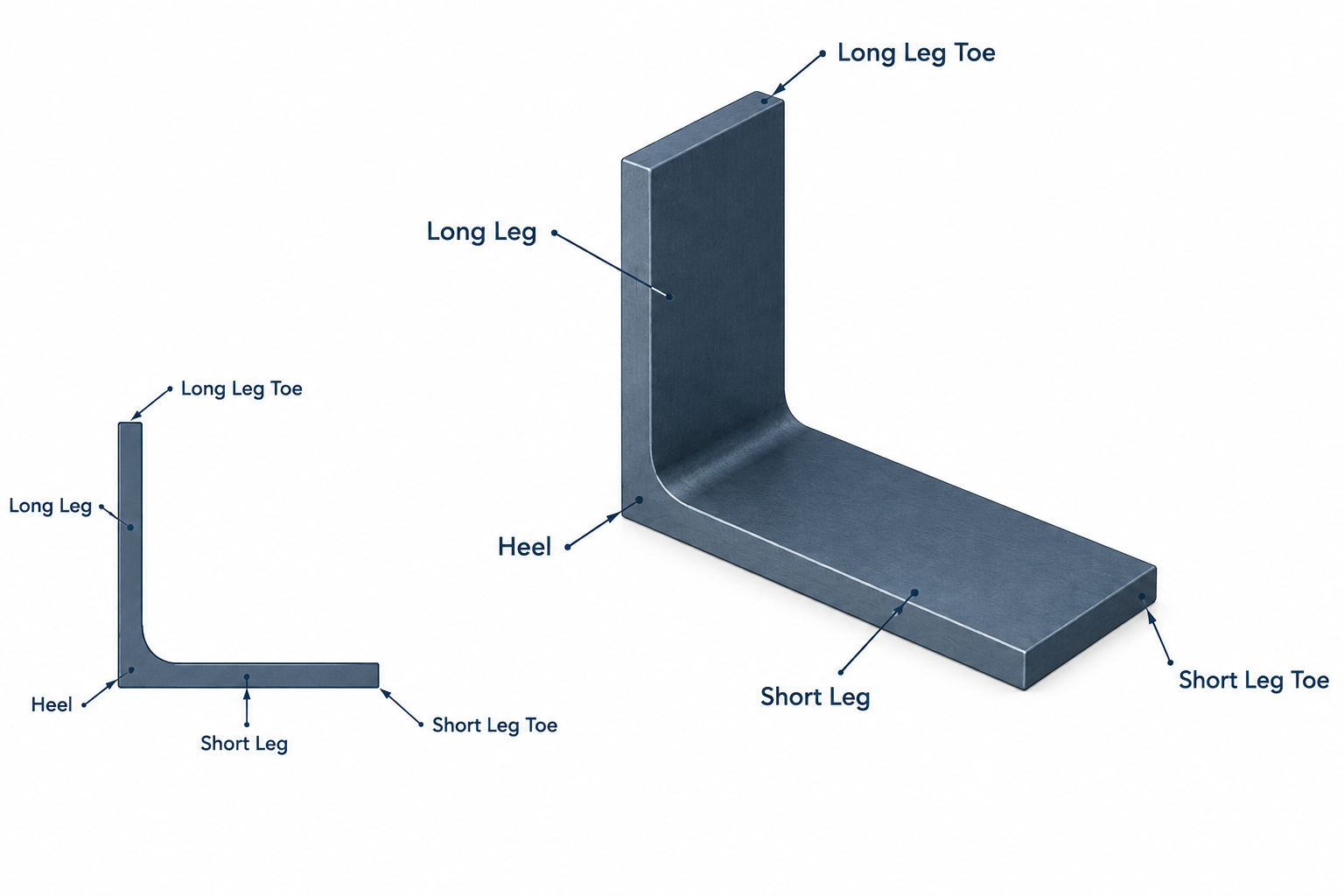
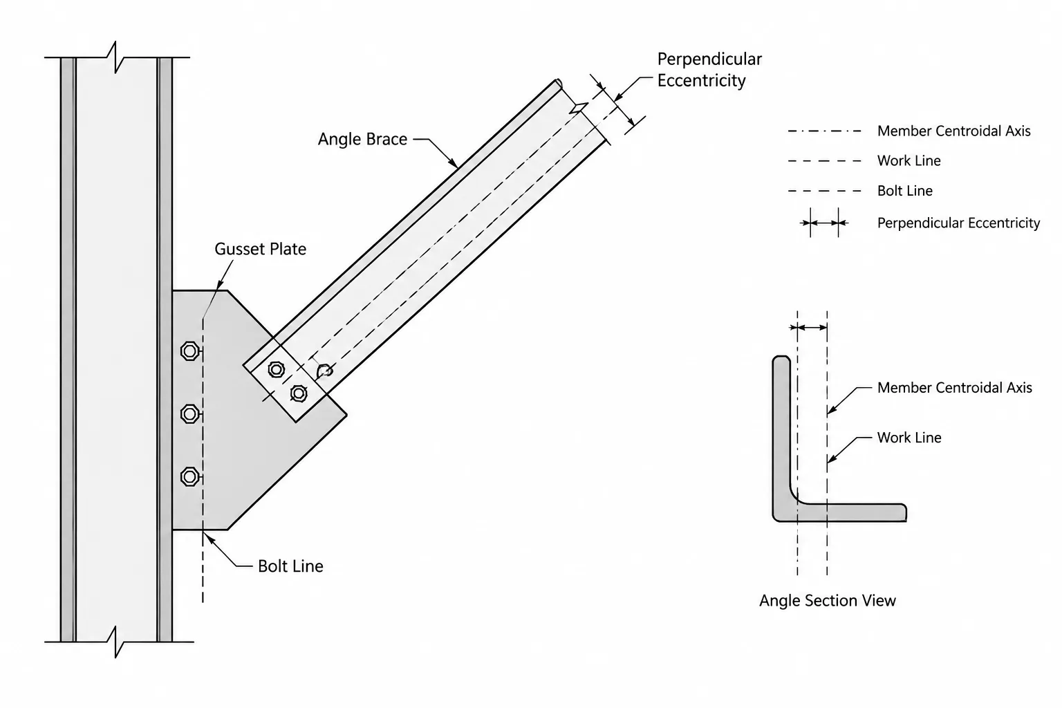
A single angle is unsymmetrical about axes parallel to its legs. Its centroid is offset from both leg centerlines, while a bolted connection is commonly arranged through one leg. The member work line, centroidal axis, bolt line, and gusset plate plane can therefore occupy different locations.
A model that places an angle by the center of its bounding box may conceal this relationship. Accurate detailing requires a deliberate insertion reference and a clear understanding of which leg connects to the supporting material.
Channels connected through the web
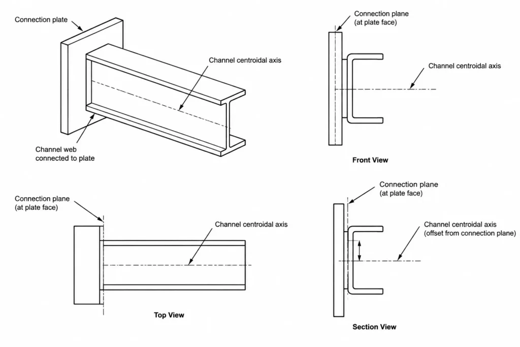
A channel is symmetric about one cross-sectional axis but not the other. Its centroid does not lie at the midwidth of the overall flange projection. A channel web may be placed against a gusset, plate, or supporting member while the member centroid remains offset from that connection plane.
Back-to-back channels can reduce or eliminate some geometric eccentricities when arranged symmetrically, but spacing plates, gaps, and unequal connection layouts can change the actual load path.
One-sided beam connections
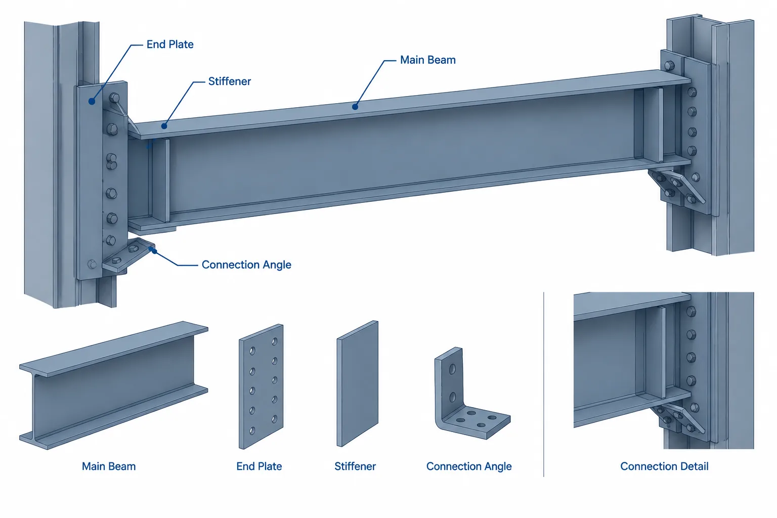
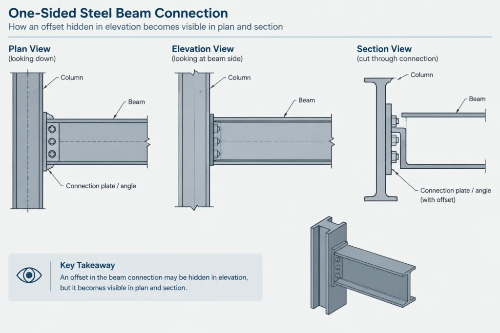
A connection attached to only one side of a beam or column web may be eccentric relative to the supporting member’s centerline. The elevation can appear conventional while the plan or section reveals an offset. This is one reason connection details should not be reviewed from a single view.
Braces and gusset plates
Brace work lines are often established from theoretical intersection points. The physical brace, gusset plate, bolts, and welds must then be arranged around those lines. Eccentricity can arise when the brace centroidal axis misses the intended work point, when the gusset is offset from the brace, or when connected members do not meet in a common plane.
HSS face connections
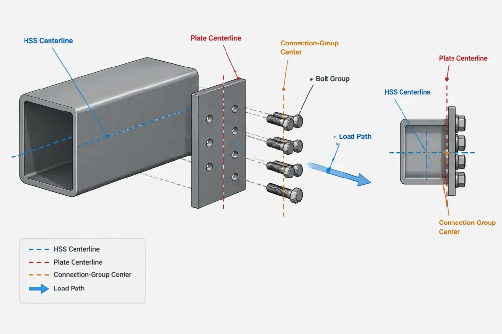
A plate welded to one face of an HSS member transfers force through that face rather than automatically through the HSS centroid. Depending on the connection geometry and direction of loading, the offset between the applied force and the member centerline may be relevant. The visible face of the HSS should not be treated as interchangeable with its centroidal axis.
Reference locations that are often confused
| Reference | What it describes | Typical detailing concern |
|---|---|---|
| Shape centroid | Center of the cross-sectional area | May not align with a connected leg, web, or face |
| Work line | Theoretical member layout line | Must remain consistent through framing plans and details |
| Bolt-group center | Center of a bolt pattern | Can be offset from both the member centroid and work line |
| Weld-group center | Center associated with the weld arrangement | Depends on the actual weld segments, not just plate geometry |
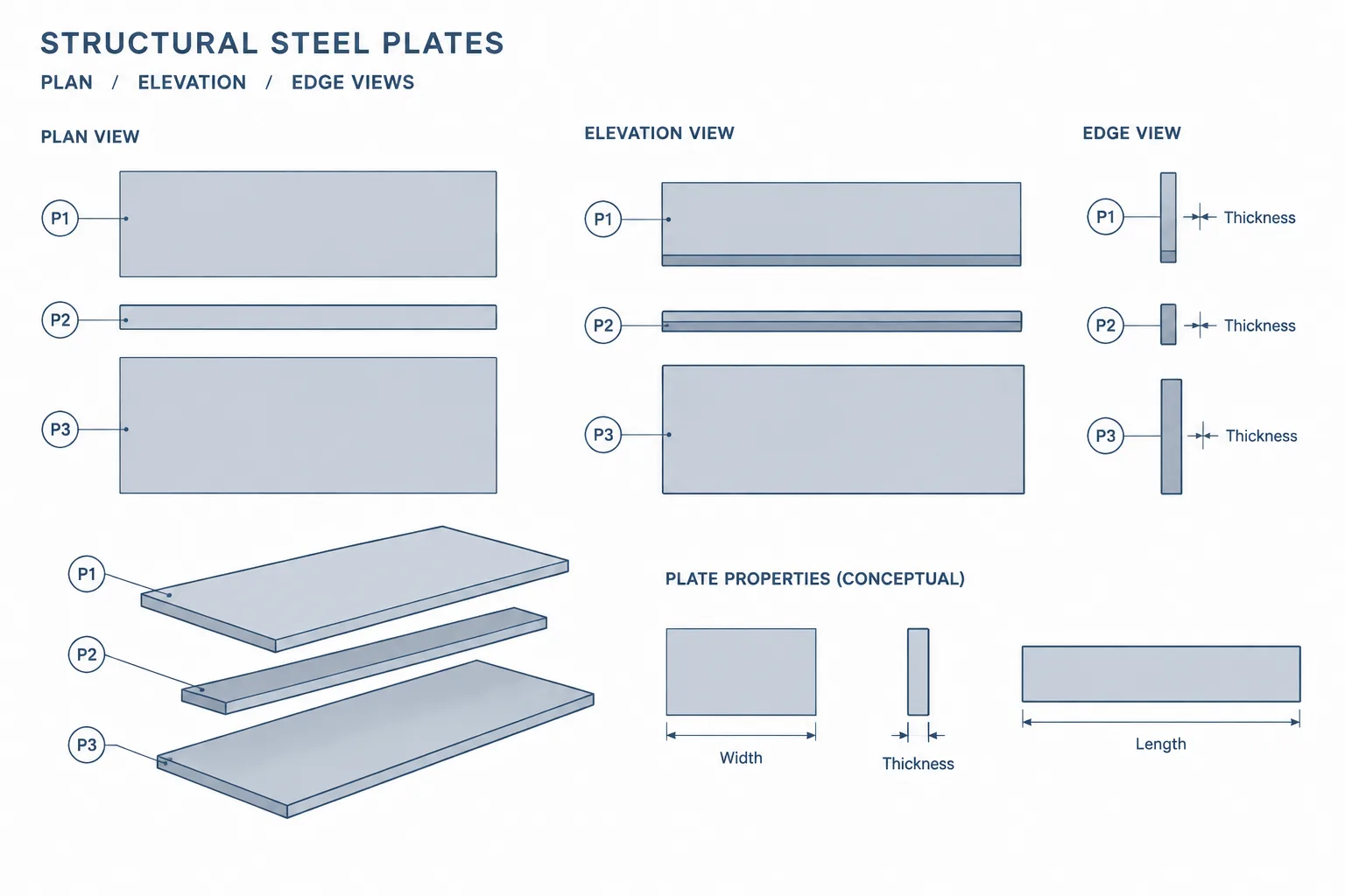
| Plate centerline | Midplane or geometric centerline of a plate | A plate may be intentionally offset or attached to one side |
| Supporting-member centerline | Layout axis of a beam, column, or brace | Does not necessarily represent the connection plane |
Why a centered CAD object may still be eccentric
CAD placement tools encourage users to snap to geometric centers, midpoints, and bounding boxes. Those points are convenient but may have no structural meaning. The center of a block extents is not necessarily the section centroid, and the center of a plate is not necessarily the center of its bolt or weld group.
This issue is especially important for angles, channels, tees, and unequal built-up members. A generic center insertion point can shift the steel relative to the intended work line. If the block is later mirrored or rotated, the connected leg or face may also change sides without an obvious warning.
A useful CAD shape should identify its insertion basis. Possible bases include the section centroid, web centerline, back of channel, heel of angle, outside face of HSS, or another defined reference. The correct choice depends on the drawing task.
A practical checking workflow
- Identify the intended load path. Determine which member, plate, bolt group, or weld group transfers the force to the next component.
- Display the relevant work lines. Keep theoretical member lines visible on a nonplot or reference layer rather than relying only on solid outlines.
- Locate section centroids correctly. Use verified shape information for unsymmetrical sections; do not infer the centroid from overall extents.
- Locate the connection plane. Confirm whether a plate is centered, placed against one face, or offset by other framing.
- Compare lines in the correct view. An offset may appear in plan, elevation, section, or a combination of views.
- Check connection-group geometry. Establish bolt and weld layouts from their actual geometry rather than the plate outline alone.
- Preserve intentional offsets. If a calculated or coordinated offset is required, dimension it from a stable reference.
- Flag unresolved conditions. Do not silently recenter a member or plate to make a detail look balanced.
Dimensioning eccentric connections clearly
Dimensions should communicate the relationship that controls fabrication and erection. Depending on the condition, this may mean dimensioning from a member work line to a plate centerline, from a steel face to a bolt line, or from a support centerline to the connected member axis.
Avoid chains that depend on several inferred centerlines. It is often clearer to show the theoretical work point, identify the member orientation, and provide a direct offset to the physical connection. Sections are particularly valuable where plates or members occupy different planes.
Notes such as “centered” should also identify the controlling object. A plate might be centered on a beam web, on an HSS face, on a work line, or between outstanding flanges. Those are not always equivalent instructions.
Eccentricity is not automatically an error
Many practical steel connections are intentionally eccentric. Fabrication access, erection sequence, architectural limits, existing construction, or the geometry of the selected shape may make an offset necessary. The engineering task is to recognize and evaluate the resulting force effects; the detailing task is to preserve the evaluated geometry.
Conversely, making a connection look symmetrical does not prove that its load path is concentric. Visual symmetry, geometric centering, and analytical concentricity are different concepts.
Final coordination checklist
- Is the member oriented with the correct web, leg, flange, or HSS face toward the connection?
- Does the model distinguish the work line from the physical member center or face?
- Is the shape centroid based on verified section data?
- Are plate and connection planes visible in at least one suitable section?
- Does the bolt or weld group align with the location assumed by the connection design?
- Are offsets dimensioned from references that fabrication can identify?
- Could mirroring, block replacement, or a shape substitution reverse or change the eccentricity?
- Have unresolved differences between the analytical model and fabrication model been communicated?
Connection eccentricity is best managed by making reference lines and planes explicit. When centroids, work lines, connection groups, and supporting faces are treated as separate concepts, CAD models become easier to coordinate and structural details are less likely to conceal unintended offsets.