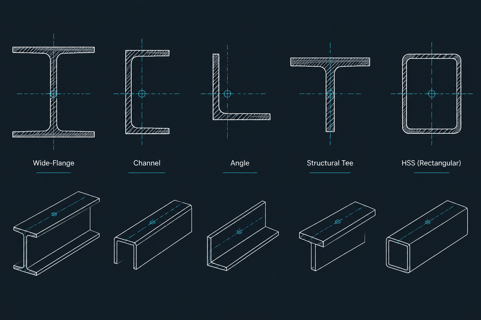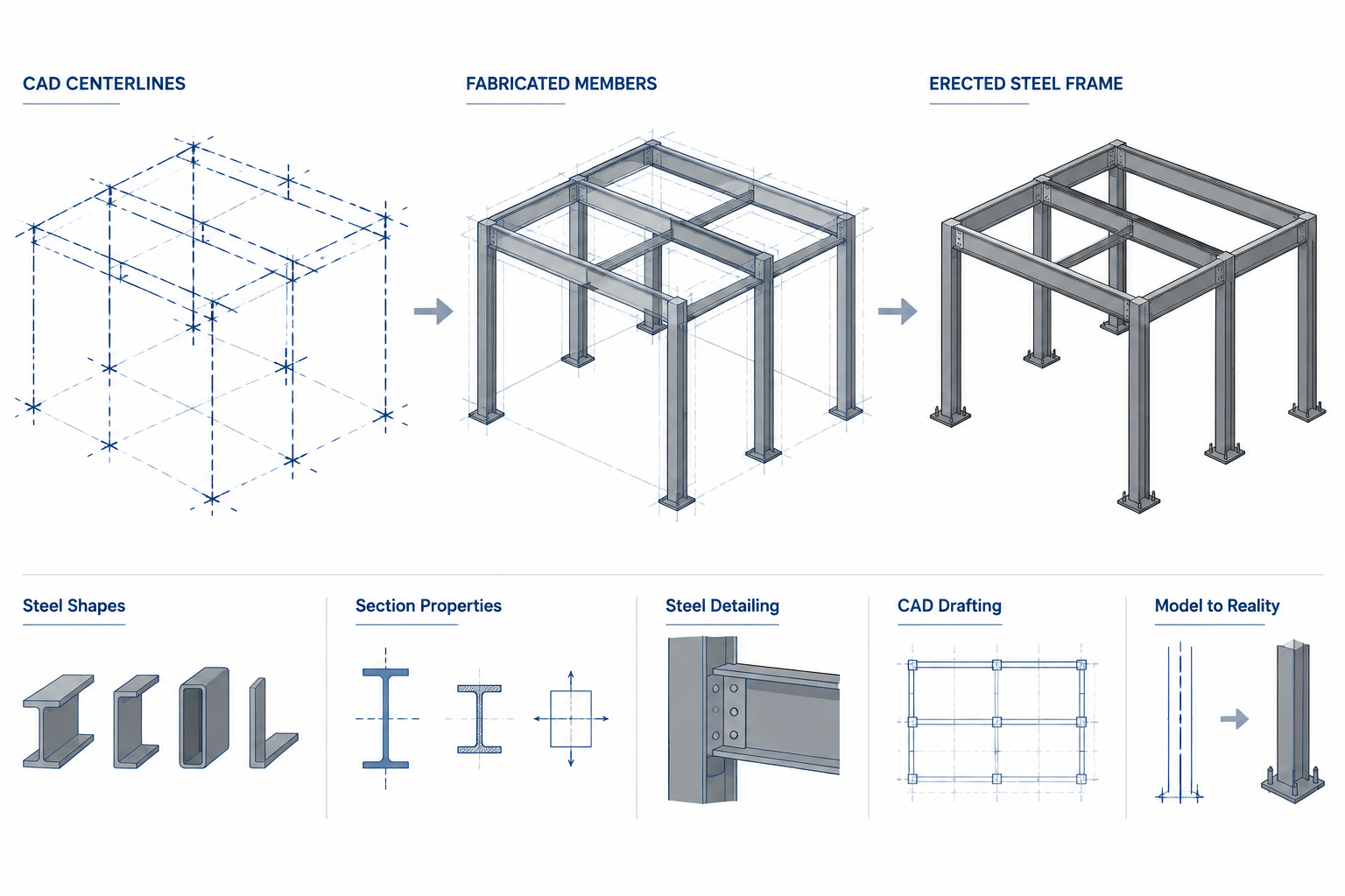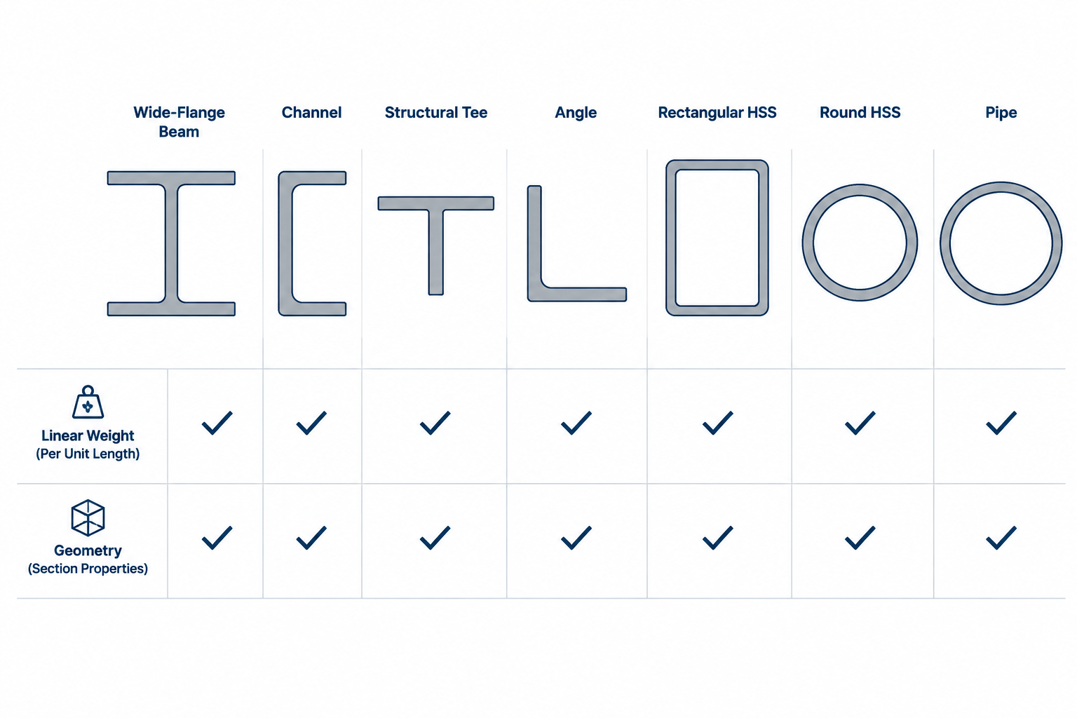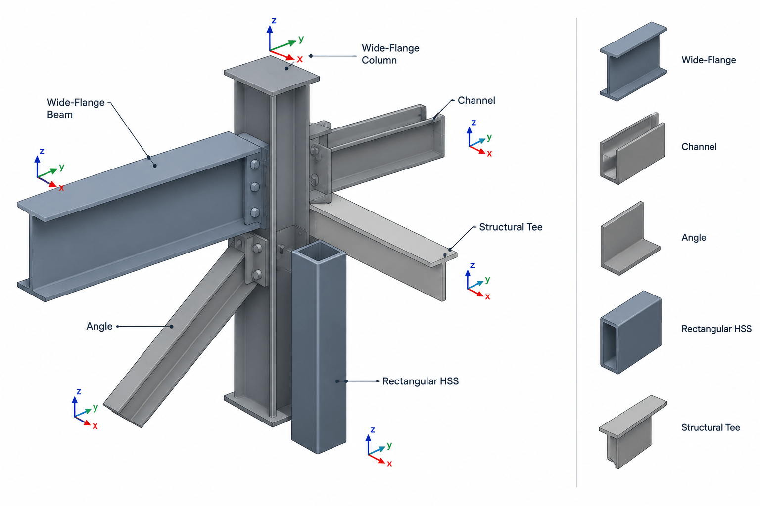
W-shapes, S-shapes, and HP shapes all resemble a capital I in cross-section, but they are not interchangeable versions of the same member. Their flange geometry, proportions, available section properties, and typical applications differ. Those differences affect everything from preliminary member selection to bolt placement and CAD block choice.
The broad term I-section describes the general profile, not a specific shape series. A note that calls for an “I-beam” may therefore be too vague for fabrication or modeling. The complete structural shape designation is needed to identify the intended section.
This guide explains how to distinguish W, S, and HP shapes and how to avoid common drafting errors when working with their profiles.
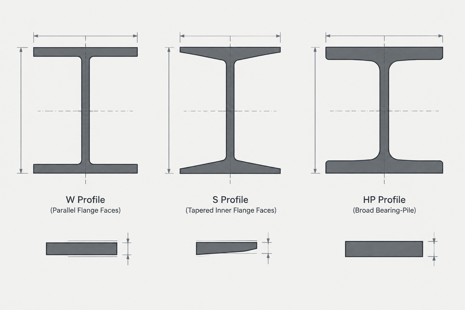
Quick comparison of W, S, and HP shapes
| Feature | W-shape | S-shape | HP shape |
|---|---|---|---|
| General name | Wide-flange shape | American Standard beam | Bearing-pile shape |
| Designation prefix | W | S | HP |
| Inner flange surfaces | Essentially parallel to outer surfaces | Tapered | Essentially parallel to outer surfaces |
| Typical visual proportion | Broad range of depths, flange widths, and weights | Relatively narrow flange appearance compared with many W-shapes | Depth and flange width are commonly similar in scale |
| Common role | Beams, columns, frames, and general structural members | Existing construction, specialized applications, and projects specifically calling for the series | Driven bearing piles and related foundation work |
| Important detailing issue | Rolled fillets and actual flange clearances | Flange taper and resulting contact geometry | Pile orientation, splices, driving details, and cut-off conditions |
This table is a recognition guide rather than a selection guide. A shape must be evaluated using its verified dimensions, section properties, material specification, loading, connections, and project requirements.
What defines a W-shape?
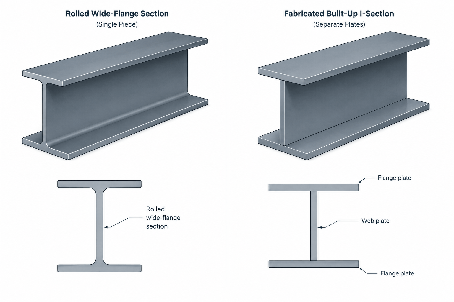
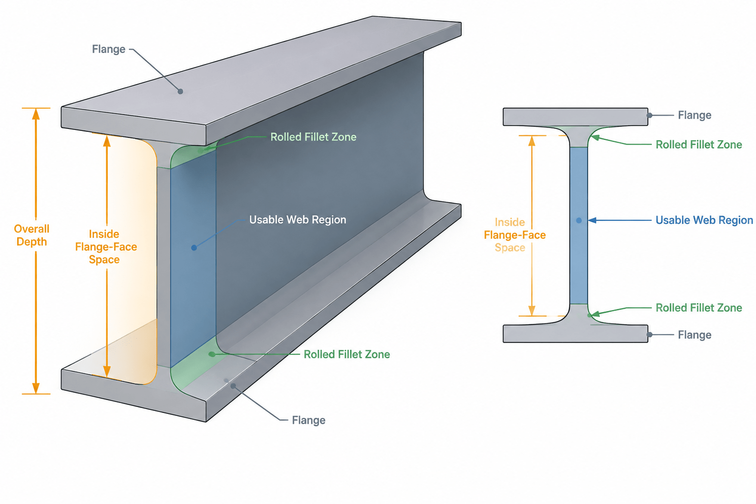
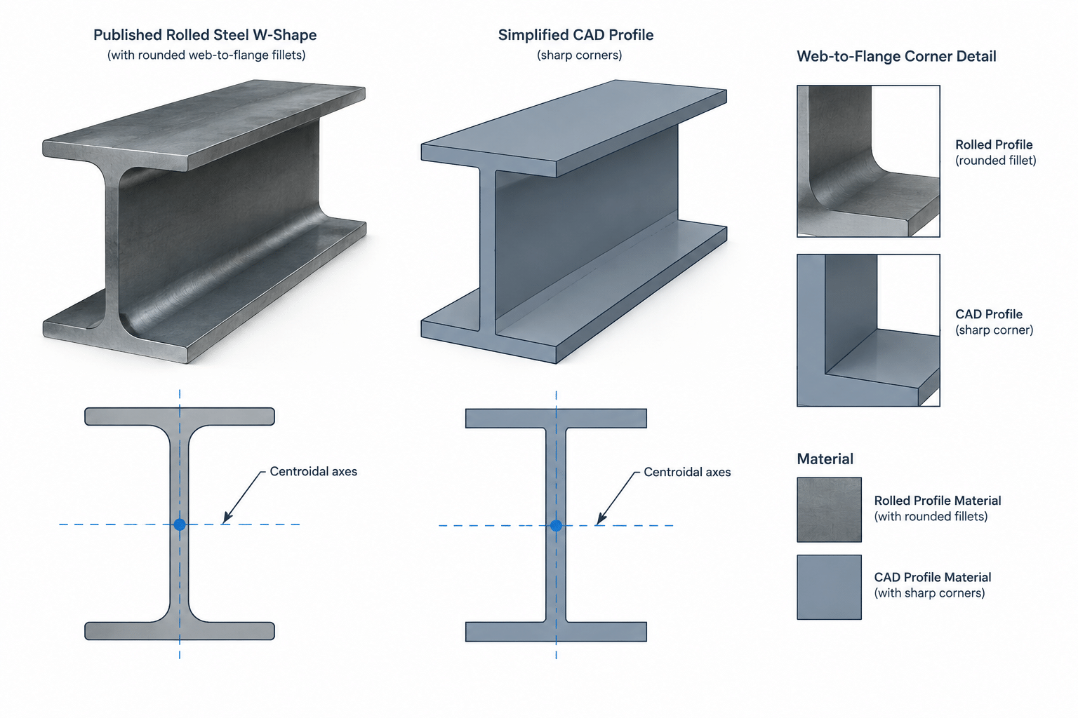
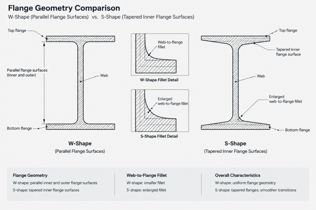
A W-shape is a rolled wide-flange section. Its two flanges are connected by a web, and the inner and outer flange surfaces are essentially parallel. The flange-to-web transitions include rolled fillets rather than perfectly sharp internal corners.
W-shapes are widely used because the series covers many combinations of nominal depth and weight. Depending on its proportions and orientation, a W-shape may serve as a beam, column, brace, transfer member, or part of a framed connection.
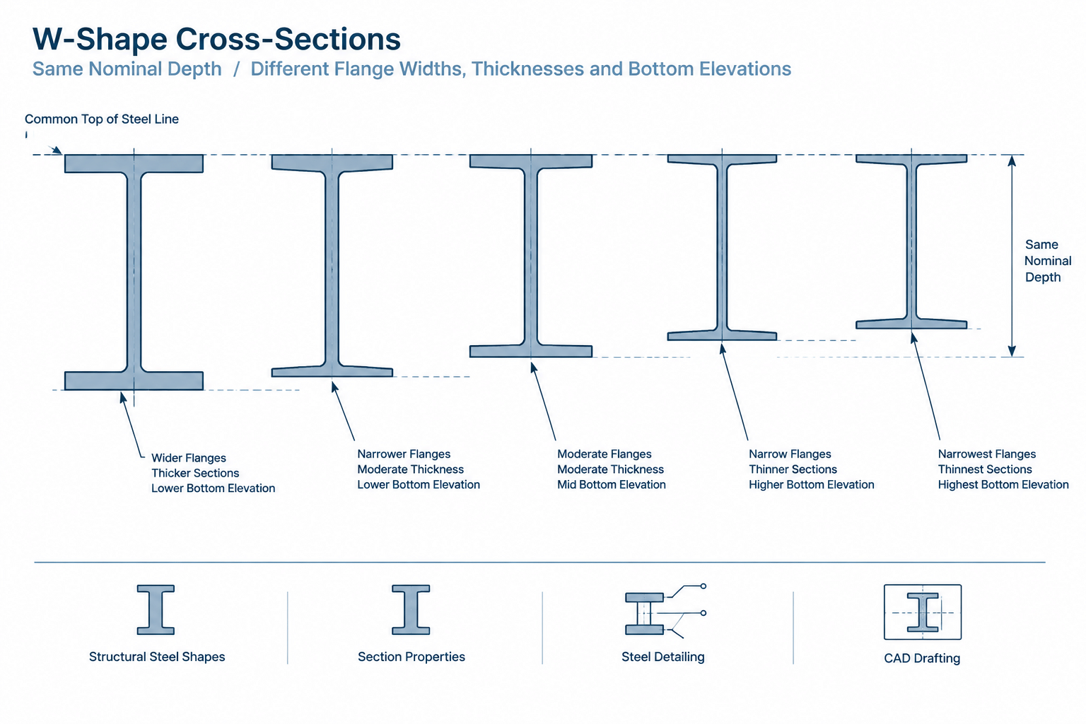
A W designation communicates the shape series, nominal depth category, and nominal weight per unit length. It does not fully describe the actual profile. Shapes sharing a nominal depth label may have different actual depths, flange widths, web thicknesses, flange thicknesses, and fillet regions. Verified table data should control the model and detail.
Practical W-shape detailing points
- Do not draw the web-to-flange intersections as sharp corners when connection fit depends on the available flat area.
- Check the actual flange width instead of centering plates from an assumed nominal profile.
- Use the correct section orientation in plans and elevations; a rotated W-shape has very different framing geometry.
- Confirm whether drawing elevations refer to the member centerline, top of steel, bottom of steel, or another work line.
What makes an S-shape different?
An S-shape is commonly called an American Standard beam. Its most recognizable feature is the taper on the inner flange surfaces. The outer flange surfaces remain useful drawing references, but the flange thickness is not represented by the same simple parallel-face geometry used for a W-shape.
This taper matters when another component bears against, clamps to, or is bolted through the flange. A rectangular plate placed against a tapered surface does not automatically achieve uniform contact. Connection components may require project-specific detailing to address the slope and available bearing surface.
S-shapes can appear in existing structures, renovation work, industrial framing, and designs that intentionally specify them. A drafter should not replace an S-shape with a visually similar W-shape merely because both profiles look like an I. Even when overall depths seem close, their flange geometry and section properties can differ substantially.
How flange taper changes CAD work
A simplified symbol may be adequate at a small plan scale, but connection sections should show geometry appropriate to the task. If a plate, bolt, washer, clip, or other item interfaces with the tapered flange, a generic parallel-flange block can conceal a fit problem.
Keep two levels of representation when practical:
- Symbolic geometry for general arrangement drawings where the member identity and orientation are the main concerns.
- Detail geometry for sections and connection views where flange slope, fillets, clearances, and contact surfaces affect fabrication.
What is an HP shape?
An HP shape is a rolled bearing-pile section. Like a W-shape, it has essentially parallel flange surfaces, but the HP series is proportioned for pile applications. Its overall depth and flange width are commonly similar in scale, giving the section a broad, compact appearance when compared with many beam-oriented profiles.
The “HP” prefix identifies the shape family; it should not be shortened to a generic H-beam label in fabrication documents. Informal terms such as H-beam vary by region and context and may not identify a unique rolled series.
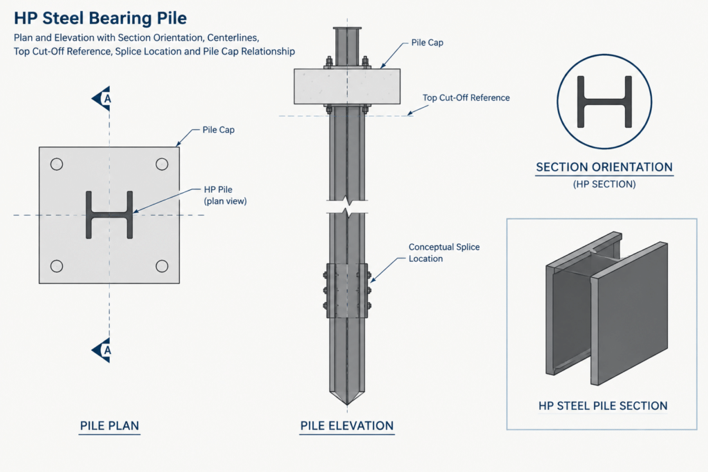
HP shapes require more than accurate cross-sectional drafting. Pile plans and details may also need to communicate:
- pile location and orientation;
- top or cut-off elevation;
- splice locations and splice concept;
- tip or driving-end treatment when specified;
- connection to pile caps, base elements, or supported framing;
- relationship to survey and foundation control points.
These items are project-specific. A generic HP outline or CAD block cannot establish the suitability of a pile detail.
Why the designation prefix must remain visible
Removing the prefix from a member label removes critical information. A depth-and-weight-style description without its series identifier can be ambiguous because different structural shape families use different geometry.
Preserve the complete designation in schedules, model properties, piece marks, callouts, and exported data. If software separates the family and size into different fields, verify that both appear in reports and drawing labels.
Also avoid relying on file names alone. A block named “I-beam” may contain a W profile, an S profile, a non-U.S. section, or merely a schematic outline. Open the geometry and compare it with a verified source before using it for dimensional work.
Choosing the correct profile for a drawing
The required drawing accuracy depends on what the view must communicate. A framing plan may represent a member with centerlines and labels, while a connection detail may require a much more faithful section.
For general arrangement views
- Show the correct member family and complete designation.
- Maintain the intended orientation.
- Place the member from the project’s stated work line or reference elevation.
- Do not infer actual depth from the nominal designation.
For connection and fabrication details
- Use verified depth, flange width, web thickness, and flange geometry.
- Account for rolled fillets and the available flat portions of the web and flanges.
- Represent an S-shape’s tapered flange where it affects fit or contact.
- Confirm bolt, weld, plate, and access geometry independently of the shape outline.
- Coordinate with the governing design documents rather than treating a library block as design authority.
Common identification mistakes
Calling every I-section a W-shape
W-shapes are common, but the visual presence of two flanges and a web does not establish the series. Read the complete designation and inspect the flange geometry.
Modeling an S-shape with parallel flanges
This can create false contact surfaces and misleading clearances. The error becomes particularly important in enlarged connection details.
Using a W-shape block for an HP pile
A similar-looking outline is not enough. The profile, designation, section properties, and pile documentation must match the specified HP shape.
Scaling a nearby section until it looks correct
Uniform scaling changes every dimension by the same ratio, while real rolled-shape series do not vary proportionally. Scaling also corrupts fillets, thicknesses, and any section properties calculated from the geometry.
Assuming visual similarity means structural equivalence
Members with comparable overall envelopes can have different area distribution, weight, stiffness, strength-related properties, and connection surfaces. Substitution requires engineering review and cannot be justified by CAD overlay alone.
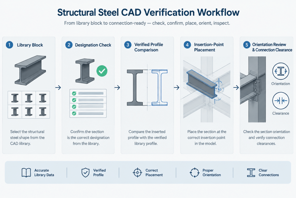
A reliable reference workflow
- Read the complete shape designation, including its prefix.
- Identify whether the member is a W, S, or HP shape before selecting geometry.
- Obtain dimensions and properties from a verified project or published shape reference.
- Insert or create the profile at full size rather than scaling a neighboring shape.
- Place it using an intentional insertion point, such as the centroid, member centerline, or another documented reference.
- Check flange orientation, elevations, setbacks, and connection interfaces.
- Use detailed fillet and flange geometry wherever fabrication clearance or bearing contact matters.
- Retain the source and verification status in the block, family, or model metadata.
The key distinction
W, S, and HP shapes share the general I-section concept, but each prefix identifies a distinct rolled-shape family. W-shapes are broad-purpose wide-flange members, S-shapes are distinguished by tapered inner flange surfaces, and HP shapes are proportioned and designated for bearing-pile applications.
For drafting, the safest approach is to preserve the full designation, use verified geometry, and match the level of profile detail to the drawing’s purpose. A symbolic I outline may communicate member location, but it should never be mistaken for verified connection geometry or a basis for substitution.