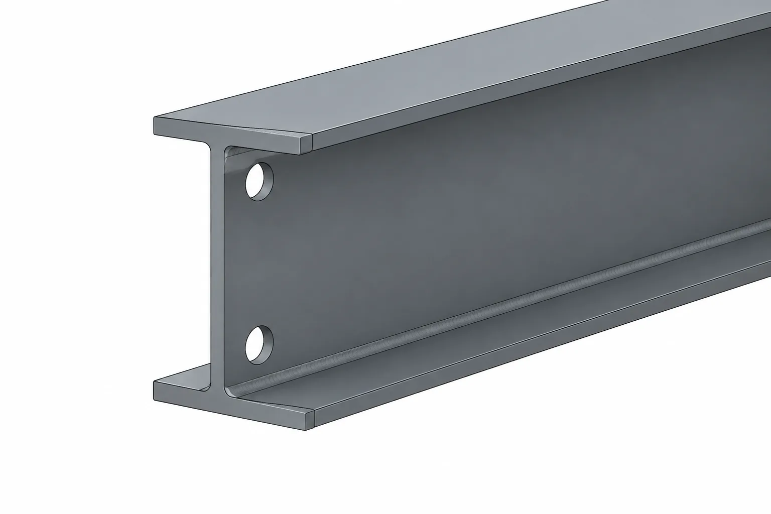
Structural steel weld access holes are deliberate openings that provide room to make, terminate, inspect, or finish a weld where intersecting material would otherwise block access. They commonly appear near the flange-to-web intersection of a W-shape or built-up member when a flange groove weld must cross the member end or splice location.
Although an access hole may look like a minor cutout, it sits in a highly consequential area of the member. Its profile can influence welding access, cut quality, stress flow, inspection, and the fit of nearby connection material. It should therefore be treated as an engineered and fabricated feature—not as an arbitrary semicircle added by a CAD operator.
What a weld access hole does
Consider a W-shape flange that is to be groove welded to another component. The web meets the flange on one side of the joint and can obstruct the welder’s path, the placement of backing, weld termination, or inspection of the completed joint. Removing a controlled portion of the web near the flange creates the necessary working space.
Depending on the connection, an access hole may help provide:
- Physical access to the flange weld joint.
- Room for weld tabs, backing, or other specified welding aids.
- Clearance for weld starts, stops, and finishing operations.
- Access for cleaning, grinding, or inspection when required.
- Separation between intersecting weld regions where directed by the connection detail.
The exact purpose must be understood before the opening is drawn. A profile intended only to clear another part is not automatically suitable as a weld access hole.
Weld access hole, cope, and clearance cut are not interchangeable
Several steel cuts can appear similar in an elevation view, but their functions differ. Correct terminology helps prevent a fabricator from applying the wrong shop practice or assuming an unintended geometry.
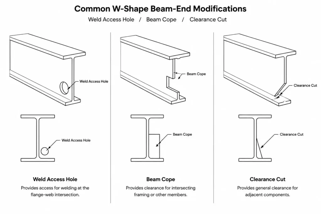
| Feature | Primary purpose | Typical location | Key detailing concern |
|---|---|---|---|
| Weld access hole | Provides access for making, finishing, or inspecting a weld | Near a web-to-flange intersection or welded splice | Engineered profile, smooth transition, and relationship to the weld |
| Beam cope | Removes flange and sometimes web material to clear a supporting member or connection | At a framing end | Fit-up, remaining web depth, connection location, and structural checks |
| Clearance cut | Avoids interference with another part or weld | Where plates, stiffeners, flanges, or welds intersect | Adequate clearance without unnecessary material removal |
| Drain or vent opening | Allows liquid, air, or processing gases to pass | Enclosed or partially enclosed assemblies | Fabrication process, coating requirements, and service environment |
Terms such as “rat hole” or “mouse hole” are used informally in some shops. Because their meaning can vary, fabrication documents should identify the intended function and show or reference the controlling profile.
Why the profile matters
A weld access hole is more than its overall length and depth. Its straight segments, curved portions, tangent transitions, and termination points form a complete contour. Abrupt corners or accidental notches may create undesirable local effects and can be difficult to cut and finish consistently.
The opening also changes the web area beside the flange. Its geometry may affect the transfer of force through the connection region, particularly where flange forces are significant or loading is repetitive. For that reason, designers and detailers should not substitute a convenient shop shape for the specified configuration without approval.
Relationship to rolled fillets
In a rolled W-shape, the web and flange meet through a curved fillet rather than a sharp inside corner. A CAD profile built from nominal web and flange rectangles may ignore that material and misrepresent where the access cut intersects the section.
Use the applicable shape information and the connection detail to establish the profile. Do not assume that the visible edge of a simplified section block represents the actual rolled surface available for cutting or welding.
Built-up members
Built-up members can have different flange-to-web geometry because their components are assembled from plates and welds. A weld access detail developed for a rolled shape should not automatically be copied to a welded girder or built-up column. Existing welds, plate thicknesses, assembly sequence, and fabrication access may all differ.
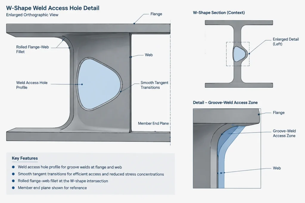
Information to show on shop drawings
A shop drawing should communicate enough information to locate and produce the opening without relying on visual scaling. Depending on project practice and the approved connection information, the detail may need to identify:
- The member end, splice, flange, or side where the opening occurs.
- Whether the cut is required at one flange or both flanges.
- The controlling dimensions or a clearly identified standard detail.
- The profile shape, including curved and straight portions.
- How the contour relates to the flange surface, web centerline, member end, and weld joint.
- Required edge finishing, surface preparation, or inspection notes when specified.
- The relationship to backing, weld tabs, stiffeners, web plates, bolts, and nearby welds.
- Whether mirrored member ends require mirrored or identical cuts.
A section or enlarged detail is usually clearer than a small opening shown only in the member elevation. The enlarged view should identify the controlling surfaces and avoid duplicate dimensions that could conflict after a revision.
CAD modeling and drawing workflow
Start with the connection requirement
Before drawing the contour, determine which weld requires access and what operation the opening must permit. A generic library block may be useful as a drafting starting point, but it should not determine the final geometry. The connection design, project criteria, and fabricator’s accepted procedure remain controlling.
Construct a continuous profile
Build the opening from constrained lines and tangent arcs or from another controlled curve definition. Check that the profile has no tiny gaps, overlapping entities, duplicate segments, or unintended sharp corners. These defects may be almost invisible on a plotted sheet but can cause problems in CNC data, plate-processing files, or model exports.
Reference stable geometry
Locate the cut from meaningful member references such as the end plane, flange surface, web centerline, or established work point. Avoid tying critical dimensions to a temporary construction line or to a simplified display outline that may change when the shape model is updated.
Check the three-dimensional context
A two-dimensional profile can look acceptable while conflicting with another component in the model. Review the opening with the complete connection visible, including:
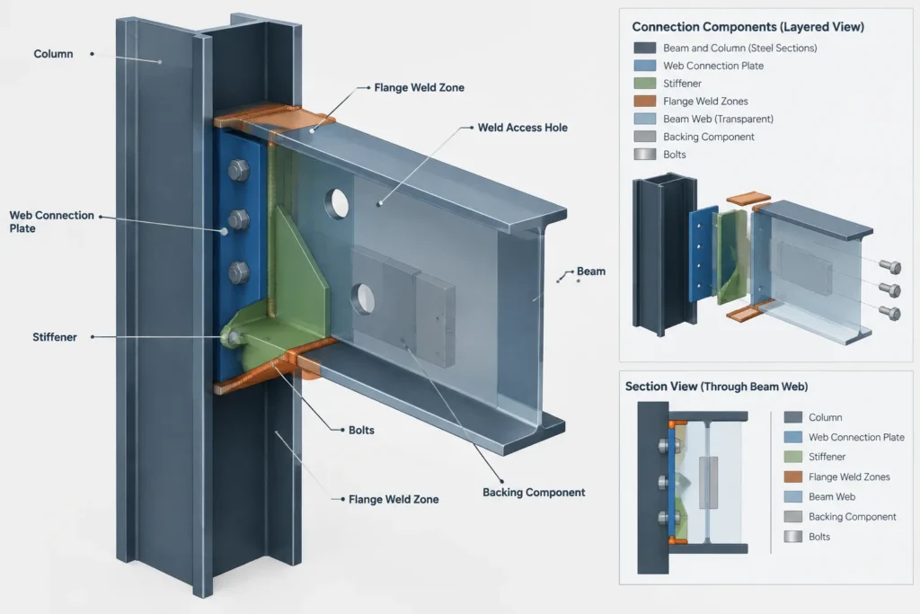
- Flange and web weld volumes.
- Backing or weld tabs where applicable.
- Web connection plates and bolt heads.
- Continuity plates, stiffeners, and doubler plates.
- Adjacent members and erection clearances.
Modeling the cut does not replace a fabrication detail. The drawing still needs to communicate intent, dimensions, and any required treatment of the cut edge.
Fabrication and inspection coordination
The process used to create the opening can affect edge condition and dimensional control. Thermal cutting, drilling followed by cutting, machining, and grinding produce different practical constraints. The detailer should not prescribe a fabrication method unless that direction is part of the project requirements or an accepted fabrication procedure.
Questions about cut-edge quality, removal of notches, grinding direction, backing treatment, weld sequencing, or nondestructive examination should be resolved among the responsible engineer, fabricator, welding personnel, and inspector. These requirements may depend on the connection type and applicable project documents.
Common detailing mistakes
- Using an arbitrary semicircle: A visually neat radius does not establish a suitable access-hole profile.
- Ignoring the rolled fillet: Simplified square-corner section geometry can place the cut incorrectly.
- Calling every web cut a cope: This obscures whether the feature is intended for framing clearance or welding access.
- Showing the opening only pictorially: Fabrication geometry should not be obtained by scaling a view.
- Copying one detail to every member: Rolled shapes, built-up members, shop splices, and field connections can require different treatment.
- Forgetting nearby components: A web plate, bolt group, stiffener, or weld may intrude into the access zone.
- Mirroring without review: Connection handedness and welding sequence can make apparently symmetric ends different.
A practical review checklist
Before releasing a drawing or model containing a weld access hole, verify that the opening has a stated purpose, an approved source for its geometry, stable locating references, and a complete contour. Confirm that it works with the actual section geometry and does not conflict with connection plates, fasteners, stiffeners, backing, or welds. Finally, make sure the shop drawing clearly distinguishes the opening from a cope or general clearance cut.
A well-detailed weld access hole is easy to identify, locate, fabricate, and inspect. More importantly, it reflects the intended connection rather than a generic CAD assumption. Final geometry and fabrication requirements should always be checked against the project documents and the applicable engineering and welding criteria.
