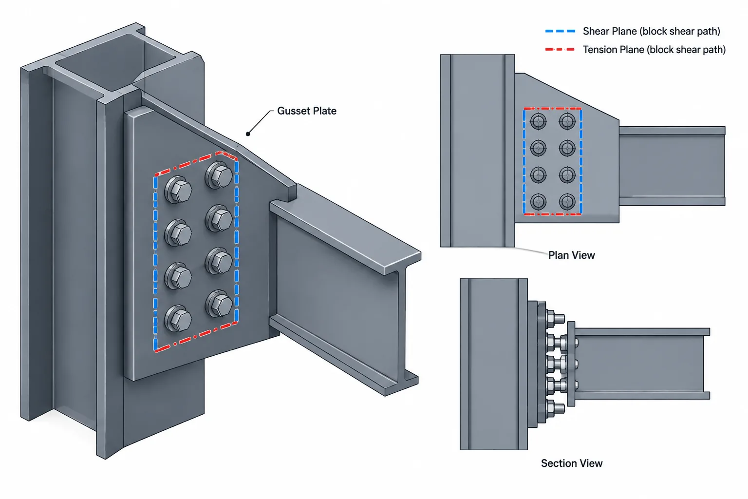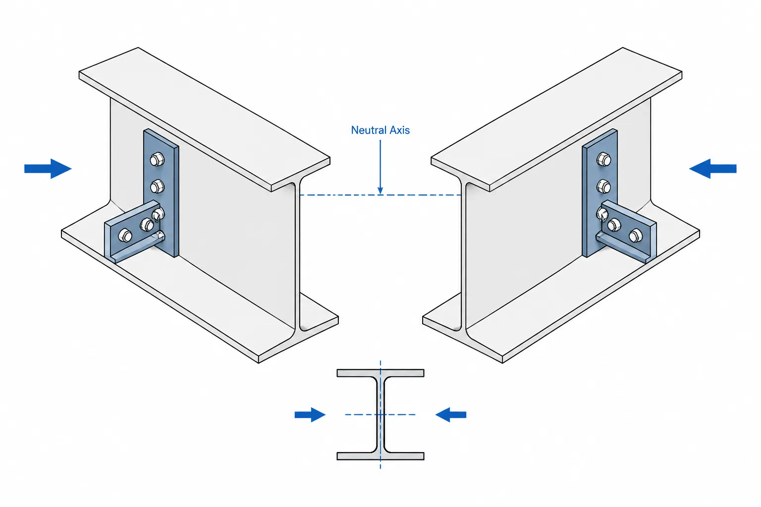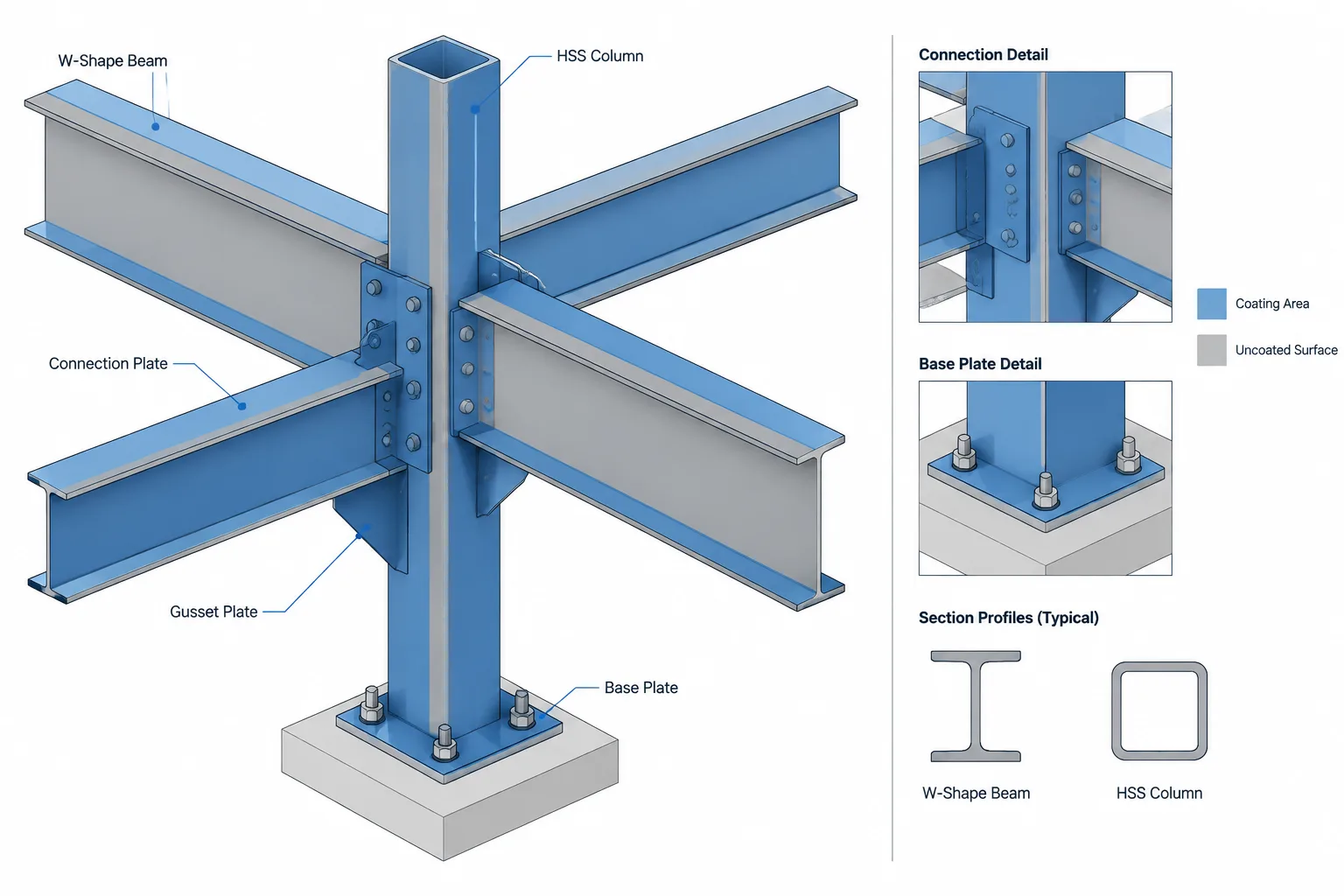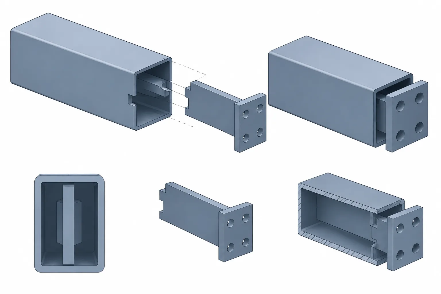
A knife-plate connection uses a relatively narrow plate aligned with the axis of a connected member. In a common hollow structural section application, the plate enters a slot cut into the HSS and may project beyond the member end to receive bolts, welds, or another connecting element. The arrangement can produce a visually compact connection, but it requires more coordination than its simple outline suggests.
Successful HSS knife-plate connection detailing depends on more than drawing a plate through the center of a tube. The slot must be constructible, the plate must fit without excessive looseness, welds must be accessible, and the assembly must be oriented correctly in the shop and field. Connection strength, HSS wall behavior, weld design, bolt design, and reinforcement requirements remain engineering decisions and should not be inferred from a generic CAD detail.
What defines a knife-plate connection?
The term knife plate generally describes a plate that presents its thin edge in one view and its broad face in the perpendicular view. Depending on the connection, it may be inserted into an HSS slot, welded to the exterior face of an HSS, or passed through the section as a through-plate.
These configurations should not be treated as interchangeable:
- Slotted end connection: The HSS end is cut so that a plate can enter the section from the end.
- Side-wall slot: A slot is formed in an HSS wall away from the member end. This introduces different cutting, welding, and internal-access issues.
- External plate: The plate terminates against the outside face of the HSS rather than entering it.
- Through-plate: The plate crosses the HSS and engages more than one wall, usually requiring coordinated openings and welds.
The drawings should show which condition is intended. A single elevation may make several of them appear similar.
Establish the connection geometry first
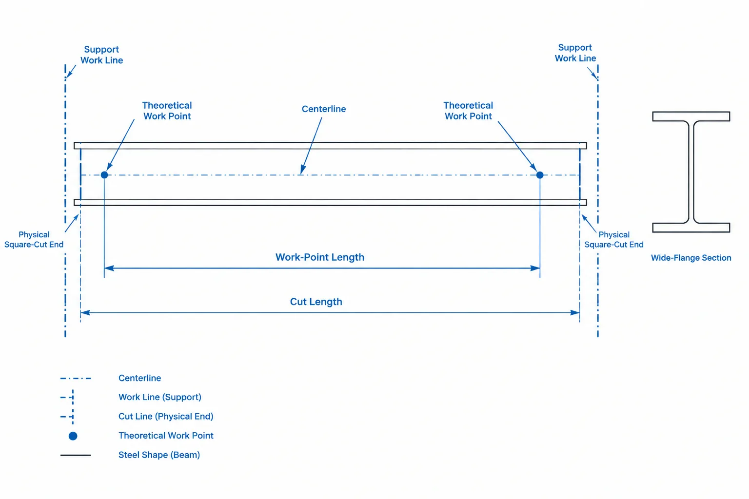
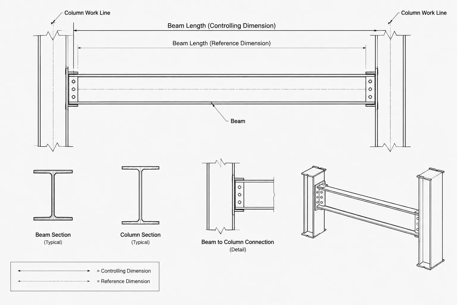
Begin with the controlling work line and member orientation. For a centered connection, the plate center plane may coincide with the HSS center plane. An offset knife plate, however, should be located from a clearly identified face, centerline, or work point. Do not rely on visual centering in a CAD view.
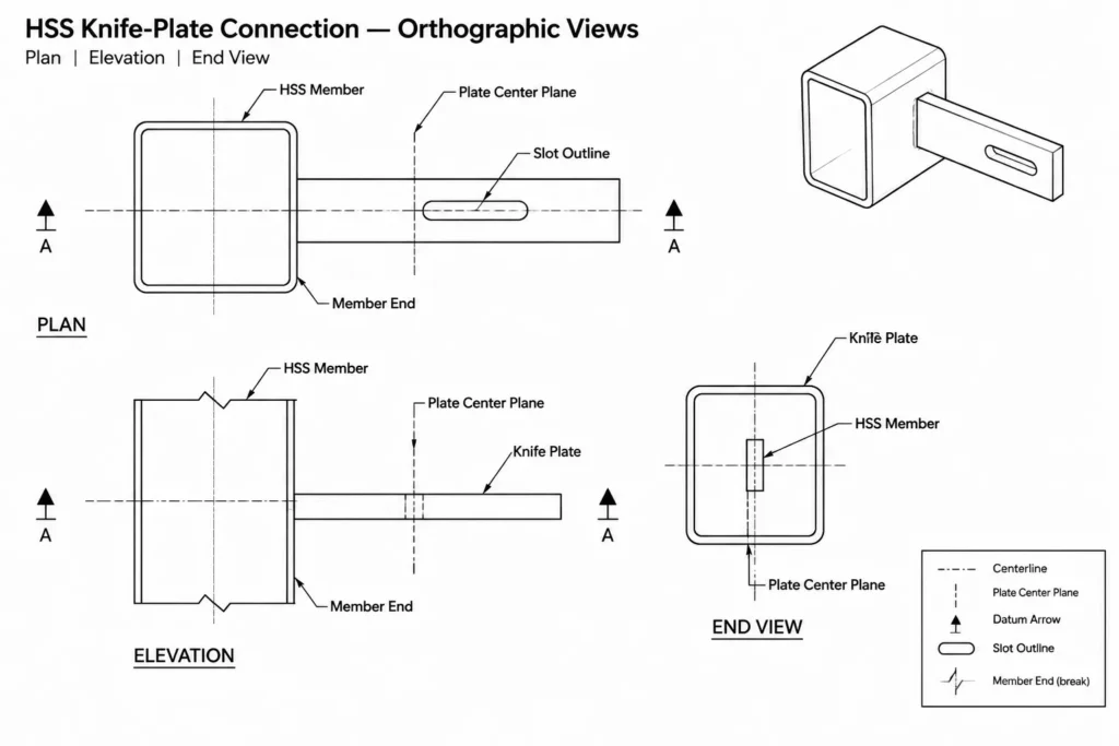
At minimum, the detail should resolve the following:
- HSS designation and orientation
- Knife-plate thickness, width, and required projection
- Plate center plane or offset from a stated reference
- Slot location, length, width, and end condition
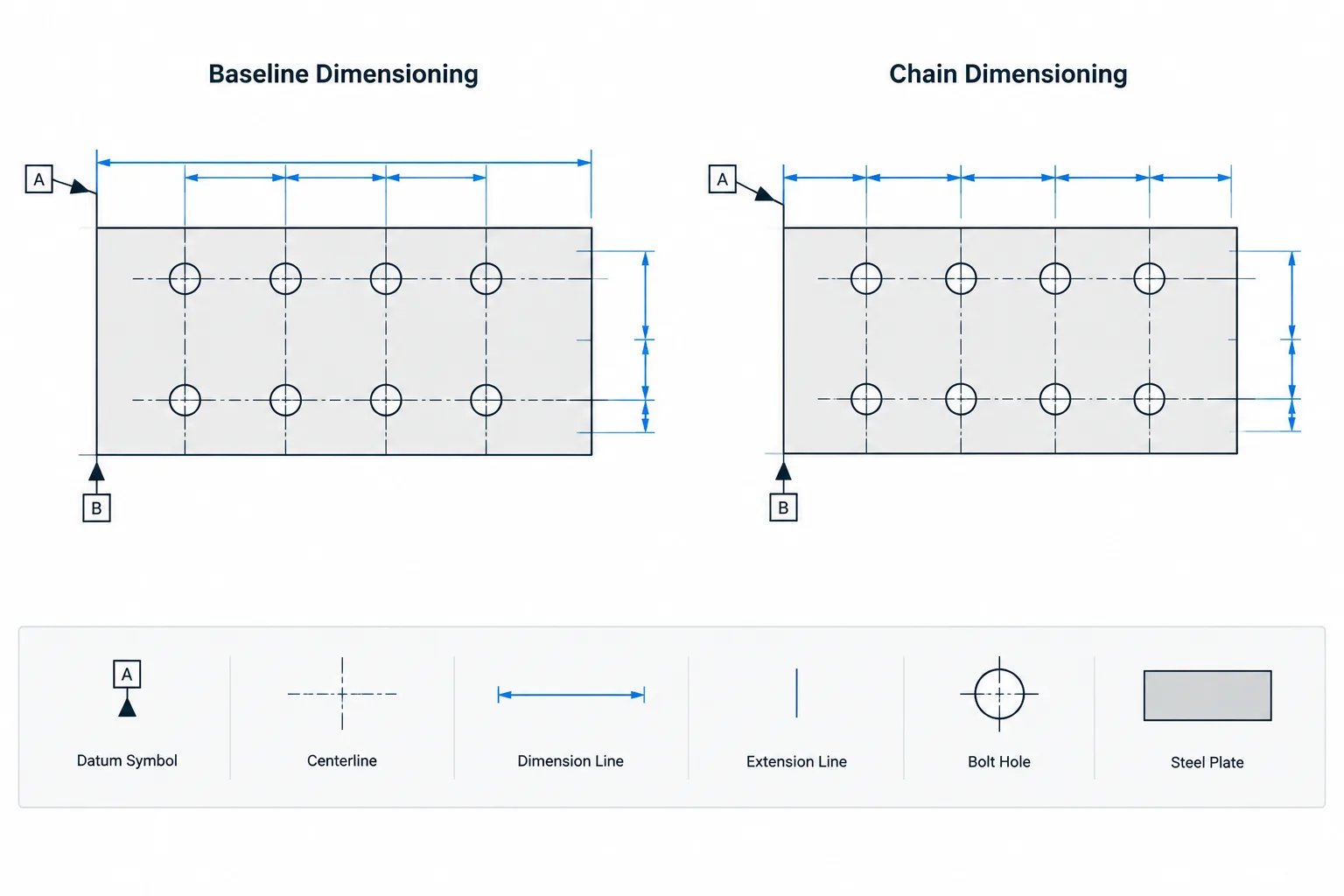
- Bolt-hole pattern and its controlling datum
- Welded edges and weld termination points
- Required member end cut
- Any cap, seal, drain, vent, backing, or reinforcement components
Rectangular HSS deserves particular attention because rotating the section changes which face receives the slot. A nearly square section can also be easy to misorient if the drawing lacks face-specific references.
Slot width is not simply plate thickness
A slot drawn at exactly the nominal plate thickness represents an idealized geometric fit, not necessarily a practical fabrication instruction. Real components are affected by plate thickness variation, HSS geometry, cutting processes, distortion, burrs, surface condition, and alignment. Conversely, making the slot unnecessarily wide can complicate weld fit-up and plate positioning.
The required slot allowance should therefore be established through the project’s connection design and fabrication criteria. The detailer should not silently select it from a visually convenient CAD offset.
Slot ends also require definition. A thermal or mechanical cutting method may leave a rounded termination, an overcut, or another process-dependent shape. If the plate is expected to reach the theoretical end of a sharp-cornered slot, the modeled geometry may be impossible to assemble. A deliberate end shape or relief may be needed, but its acceptability must be verified for the actual connection.
Model nominal and fabrication geometry separately when useful
A practical CAD workflow is to maintain a clear distinction between the design intent and the cut geometry. The plate center plane and theoretical member end can control layout, while a separate slot outline represents the fabrication opening. This makes it easier to check fit without allowing the slot clearance to shift the connection work line.
Plate projection and insertion depth
Two plate lengths are often relevant: the portion inserted into the HSS and the portion projecting outside it. The inserted portion affects weld layout and force transfer. The projecting portion controls bolt placement, edge geometry, connected-part clearance, and erection access.
Dimensioning only the plate’s overall length can leave its position ambiguous. A more useful detail identifies the plate relative to the HSS end or another stable datum. If the plate passes through the section, its location should be controlled in both orthogonal views.
Where a bolt group is placed in the projecting portion, verify that the bolt pattern is dimensioned from the intended connection work point rather than from an incidental plate edge. Plate edges may change during connection development, while the work point often remains fixed.
Weld access and weld continuity
The visible plate-to-HSS intersection does not automatically indicate which surfaces can be welded. Access depends on slot position, HSS size, plate projection, adjacent components, and the sequence of assembly. A weld that appears open in a section view may be blocked in the actual shop orientation.
Review the connection from multiple directions and ask:
- Can the welder reach every specified weld location?
- Does the weld continue around the HSS end, stop at a corner, or occur only along selected walls?
- Is the HSS corner radius close to the weld path?
- Will another plate, bolt, or member obstruct the welding operation?
- Can the connection be inspected as required?
- Could weld shrinkage pull the knife plate out of alignment?
Weld symbols should identify the intended joint rather than merely point toward the general connection. The connection designer must specify the weld type, extent, size, and any special preparation.
Internal interference and HSS corner geometry
The interior of an HSS is not a perfect sharp-cornered rectangle. Rounded corners reduce the usable clear width near the corner regions. A plate that fits through an idealized rectangular outline may interfere with the actual inside corner geometry, particularly if it is wide, skewed, or positioned near a wall.
A simplified HSS CAD block may omit internal radii. That can be appropriate for general arrangement drawings but inadequate for a tight-fit connection study. When clearance is critical, use verified section geometry or obtain fabrication input rather than scaling a schematic profile.
Also consider the longitudinal weld seam where its orientation matters to cutting, welding, appearance, or connection behavior. Seam location should not be assumed from a generic model.
Common detailing risks and useful checks
| Detailing issue | Possible result | Recommended check |
|---|---|---|
| Slot centered graphically but not dimensionally | Plate offset or member rotation error | Dimension the plate plane from a defined centerline or face |
| Slot modeled equal to plate thickness | Assembly interference | Confirm the intended fabrication allowance |
| Sharp theoretical slot end | Plate cannot seat as modeled | Review the actual cutting method and termination geometry |
| Only one view provided | Ambiguous slot face or plate orientation | Add an orthogonal view or section |
| Weld shown without access review | Unworkable or incomplete weld | Check access in the assembled condition |
| Plate projection controlled from a changing edge | Bolt-group location shifts during revisions | Use a stable work point or member-end datum |
| Idealized HSS interior used for fit | Interference with rounded corners | Check verified internal geometry where fit is critical |
Drainage, venting, sealing, and corrosion considerations
Slotting an HSS can create paths for water and debris or produce enclosed spaces affected by fabrication and coating operations. Whether the member should be sealed, vented, drained, or provided with access openings depends on the assembly, exposure, coating process, and project requirements.
These features should be coordinated before shop drawings are complete. A drain or vent added late may conflict with the knife plate, welds, bolt group, or architectural appearance. Avoid presenting a fully sealed HSS in a detail unless that condition has been intentionally specified and reviewed.
A practical CAD and shop-drawing workflow
- Set the work line. Establish the HSS axis, connection work point, and local orientation.
- Place the plate center plane. Control it with dimensions or constraints rather than visual alignment.
- Model the HSS end and slot. Include realistic corner or slot-end geometry when it affects fit.
- Check insertion and projection. Confirm the plate reaches its intended position without internal interference.
- Add connected parts and fasteners. Review edge conditions, access, and erection movement.
- Map the welds. Identify each welded interface and verify physical access.
- Review orientation in all views. Use a section or end view to eliminate face ambiguity.
- Coordinate fabrication features. Resolve vents, drains, caps, coatings, and seam orientation where applicable.
- Run a revision check. If the HSS or plate changes, recheck the slot, weld path, bolt layout, and mating parts rather than updating only the callout.
What a reusable CAD detail can and cannot provide
A reusable knife-plate CAD detail can communicate typical relationships, layer organization, view arrangement, and dimensioning strategy. It cannot establish the required connection capacity or guarantee compatibility with a selected HSS. Wall behavior, local yielding or rupture, plate behavior, weld demands, bolts, load direction, eccentricity, and connection stiffness may all affect the engineered solution.
Treat standard details and blocks as drafting starting points. Before release, replace generic geometry with verified project information and obtain the required engineering and fabrication review. For knife-plate connections, a small geometric assumption can determine whether the assembly fits at all.