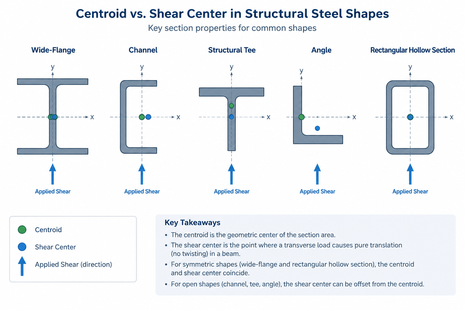
The centroid and shear center are two different reference points used to describe structural steel sections. They coincide for many familiar shapes, which can make the distinction easy to overlook. For channels, tees, angles, and other unsymmetrical or singly symmetric sections, however, assuming they are the same point can hide an important source of torsion.
The centroid is primarily associated with section geometry, axial loading, and bending. The shear center identifies where a transverse load can act without causing the cross section to twist under idealized beam behavior. Understanding both points helps designers and detailers interpret section-property data, recognize connection eccentricity, and create CAD models that represent the intended load path.
What Is the Centroid of a Steel Section?
The centroid is the geometric center of area of a cross section. If a uniform axial force passes through this point, the idealized section experiences axial stress without bending caused by load eccentricity. Centroidal axes also provide the common reference for section properties such as moments of inertia, section moduli, and radii of gyration.
Symmetry often makes the centroid easy to locate:
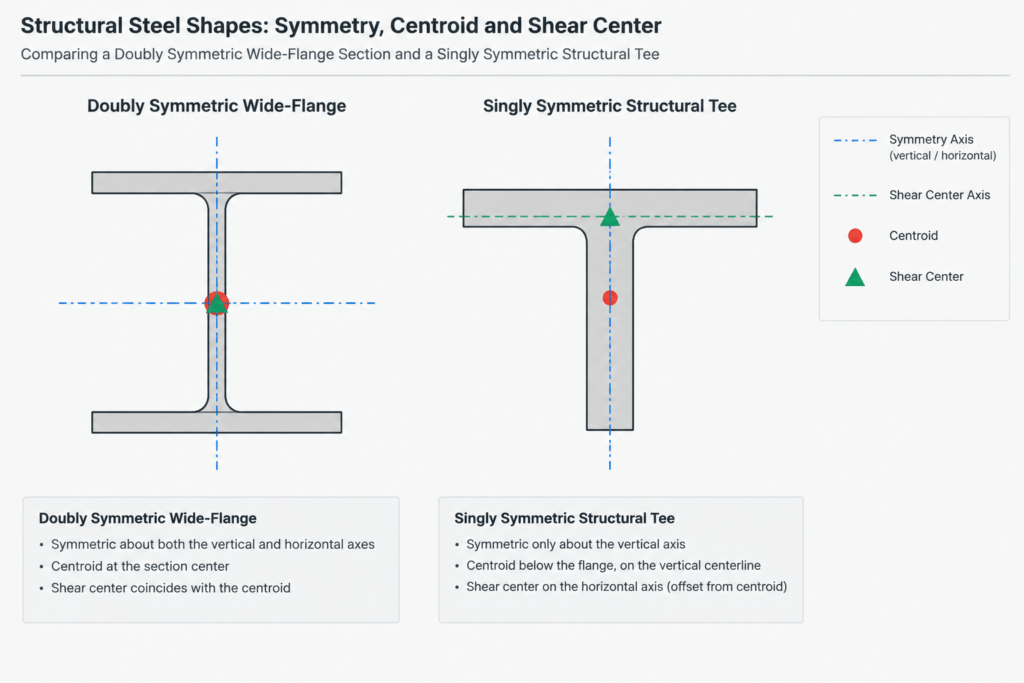
- For a doubly symmetric W-shape, it lies at the intersection of the web centerline and the mid-depth line.
- For a rectangular or square HSS, it lies at the geometric center of the section.
- For a channel, it lies on the horizontal axis of symmetry but is offset from the web centerline.
- For a structural tee, it lies on the stem centerline but generally not at the section’s mid-depth.
- For an unequal-leg angle, the centroid is offset from both leg centerlines and must be located from verified section data or calculation.
Shape tables may provide centroid coordinates for sections whose centroid is not obvious. The coordinate convention must be checked carefully because the origin may be placed at an outside face, a back of web, a leg edge, or another defined reference.
What Is the Shear Center?
The shear center is the point in the cross-sectional plane through which a transverse load produces bending without twisting the section in the idealized case. When the load acts away from that point, the offset creates a torsional moment equal to the load multiplied by its perpendicular eccentricity from the shear center.
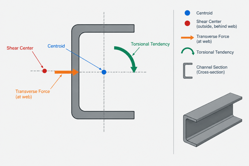
The shear center is a property of the cross-sectional geometry, not necessarily a point located within the steel area. For some open sections, it lies outside the physical outline. That does not make it unusable; it means that a force applied through a practical connection may have unavoidable eccentricity relative to the section’s non-twisting load line.
Locating the shear center depends on how shear flow develops through the section. This is why it cannot generally be found by simply balancing areas or identifying the centroid.
How Symmetry Affects the Two Points
| Shape type | Centroid and shear-center relationship | Practical observation |
|---|---|---|
| Doubly symmetric W- or I-shape | They coincide at the intersection of the symmetry axes. | A load through the web plane and section center avoids section eccentricity in the idealized model. |
| Square or rectangular HSS | They coincide at the geometric center because of double symmetry. | Connections attached to only one wall can still introduce local effects and an eccentric load path. |
| Channel | Both lie on the axis of symmetry, but they do not coincide. | The shear center is outside the section, on the side opposite the flange tips. |
| Structural tee | Both lie on the section’s symmetry axis, but their positions along that axis may differ. | A connection through the stem does not by itself prove that the load passes through the shear center. |
| Angle or other unsymmetrical open section | They generally do not coincide, and the shear center is not constrained to a centroidal symmetry axis. | Applied loads commonly create combined bending and torsion unless the full load path and restraint are considered. |
These relationships describe idealized cross-sectional behavior. Actual member response also depends on span, boundary conditions, bracing, connection stiffness, load distribution, and whether warping is restrained.
Why Channels Are a Common Detailing Concern
A channel has one axis of symmetry, but its flanges project to only one side of the web. Under transverse shear, the flange shear flows create a twisting tendency unless the force passes through the shear center. That point lies outside the channel, behind the web rather than in the open side of the section.
In practice, a supported item may connect to the channel web, flange tips, or one flange. None of these connection locations should automatically be treated as a torsion-free load line. Channel lintels, girts, stringers, edge members, and equipment supports deserve particular attention when loads are applied away from the web plane or when the member has limited rotational restraint.
Back-to-back channels can provide a more symmetric built-up arrangement, but only if their spacing, connectors, and load transfer cause them to act as intended. Merely drawing two channels together does not establish composite action or eliminate every torsional effect.
Centroidal Eccentricity and Shear-Center Eccentricity
Two different eccentricities may need to be considered when reviewing a steel detail:
- Axial-load eccentricity: An axial force that does not pass through the centroid produces a bending moment in addition to axial force.
- Transverse-load eccentricity: A transverse force that does not pass through the shear center creates a torsional moment in addition to shear and bending.
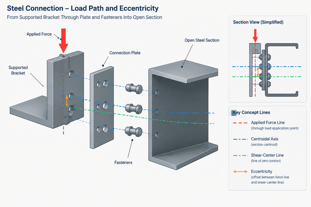
A connection can involve both at once. For example, a bracket fastened to one side of an open section may offset the applied force from the centroidal axes and from the shear center. The resulting behavior can include axial force, bending about one or both axes, shear, uniform torsion, warping-related effects, and local deformation at the connection.
This is why a line representing the member center in a framing plan should not automatically be assumed to represent every relevant geometric or loading reference.
Using Shape Tables and CAD Data Correctly
Section-property tables commonly emphasize centroidal properties because they are needed for many routine calculations. Shear-center coordinates may be listed separately, provided only for certain shape families, or omitted entirely. When they are provided, confirm the coordinate origin, axis orientation, sign convention, and whether the value applies to the published rolled shape or to an idealized model.
A practical CAD or modeling workflow includes the following checks:
- Insert verified geometry. Use reliable shape dimensions rather than tracing a generic symbol or scaling a block by eye.
- Establish the local axes. Mark the section’s centroidal axes and confirm how they correspond to the model axes.
- Identify the actual load line. Trace the force through plates, bolts, welds, seats, clips, and supported components rather than stopping at the member centerline.
- Locate the shear center when relevant. Obtain it from verified section data or a suitable engineering calculation; do not estimate it from the outline.
- Show eccentricity explicitly. A section or detail view is often more informative than a framing plan for an offset connection.
- Coordinate analytical and physical models. A model that places loads at a member node may not capture the offsets visible in the fabrication detail.
CAD blocks are useful for representing shape geometry, but they do not determine the structural behavior of a connection. The insertion point of a block may be at the centroid, a corner, the back of a web, or an arbitrary drafting origin. It should be verified before the block is used to measure load eccentricity.
Common Misinterpretations to Avoid
“The member centerline is the centroid.”
It may be, but drafting centerlines are often chosen for layout convenience. A channel might be located by its back of web, while an angle may be located by a leg face or work point.
“A load through the web cannot twist the member.”
This is generally reasonable for a doubly symmetric I-shape when the load acts in the web plane, but it is not a universal rule. The shear center of a channel is not in its web, and connections can introduce additional offsets.
“If the shear center and centroid coincide, torsion is impossible.”
Coincidence only removes torsion for a load that actually passes through that common point in the applicable direction. Loads attached to one flange or one HSS wall may still be eccentric. Applied couples and connection geometry can also create torsion directly.
“The shear center alone predicts the complete response.”
It is an important cross-sectional reference, not a complete member analysis. Restraint against rotation and warping, connection stiffness, local wall or flange behavior, load position along the span, and geometric imperfections can all affect response.
A Useful Review Question for Steel Details
When reviewing a section, ask three separate questions: Where is the centroid? Where is the shear center? Where does the force actually act? If those points or lines do not coincide, the offsets should be visible in the analysis assumptions and understood in the detail.
This approach is especially valuable for channels, tees, angles, edge beams, cantilevered brackets, and members loaded through one side. It helps connect shape-table information to real drafting decisions without treating a section designation or CAD outline as a substitute for engineering verification.


