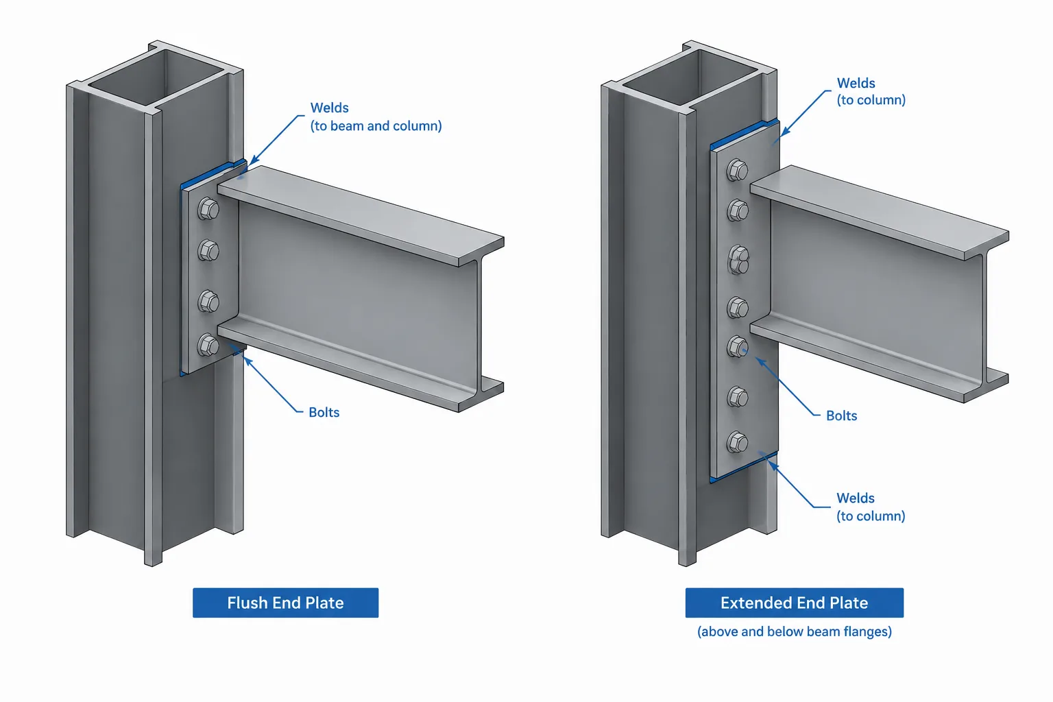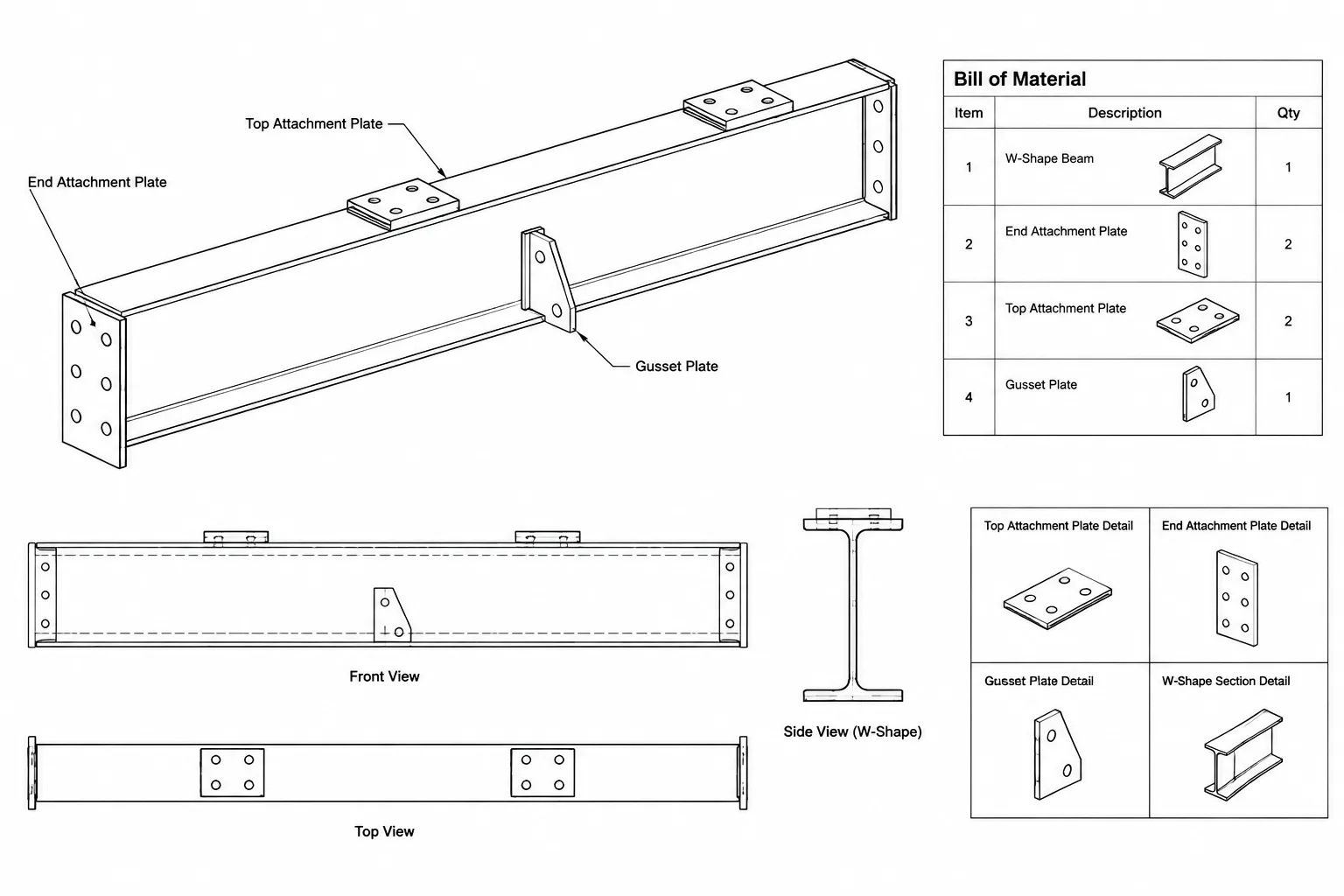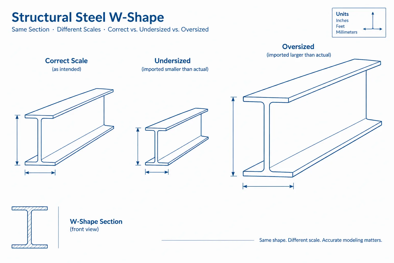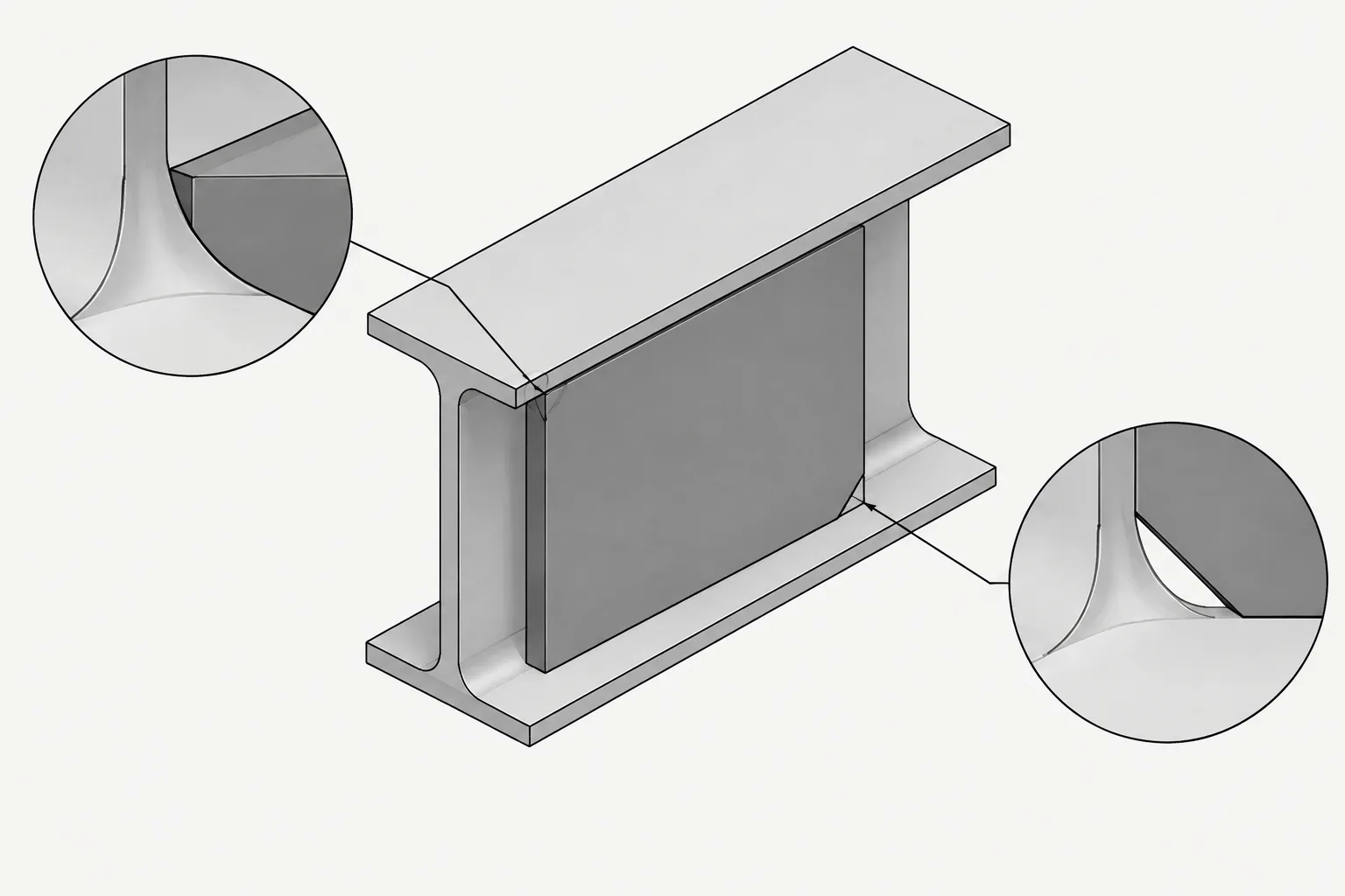
A rectangular plate does not always fit into the apparently rectangular space between the web and flange of a rolled steel shape. W-shapes, channels, structural tees, and similar sections have curved transition regions where the web meets a flange. A connection plate, stiffener, diaphragm, or other detail part extending into that region may require a corner clip or relief to avoid interference.
The required detail can look minor on a drawing, but it affects fabrication, fit-up, welding, inspection access, and the accuracy of material models. The plate cannot simply be trimmed until it appears to fit. Its relief geometry must be coordinated with the actual rolled shape, the intended plate position, the weld termination, and the connection design.
Why a square plate corner may not fit
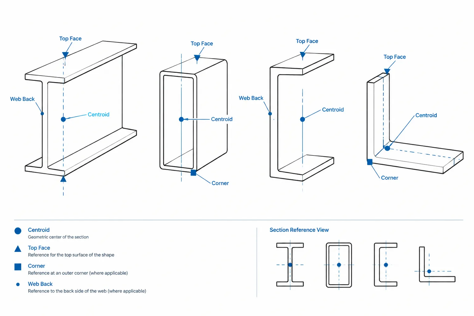
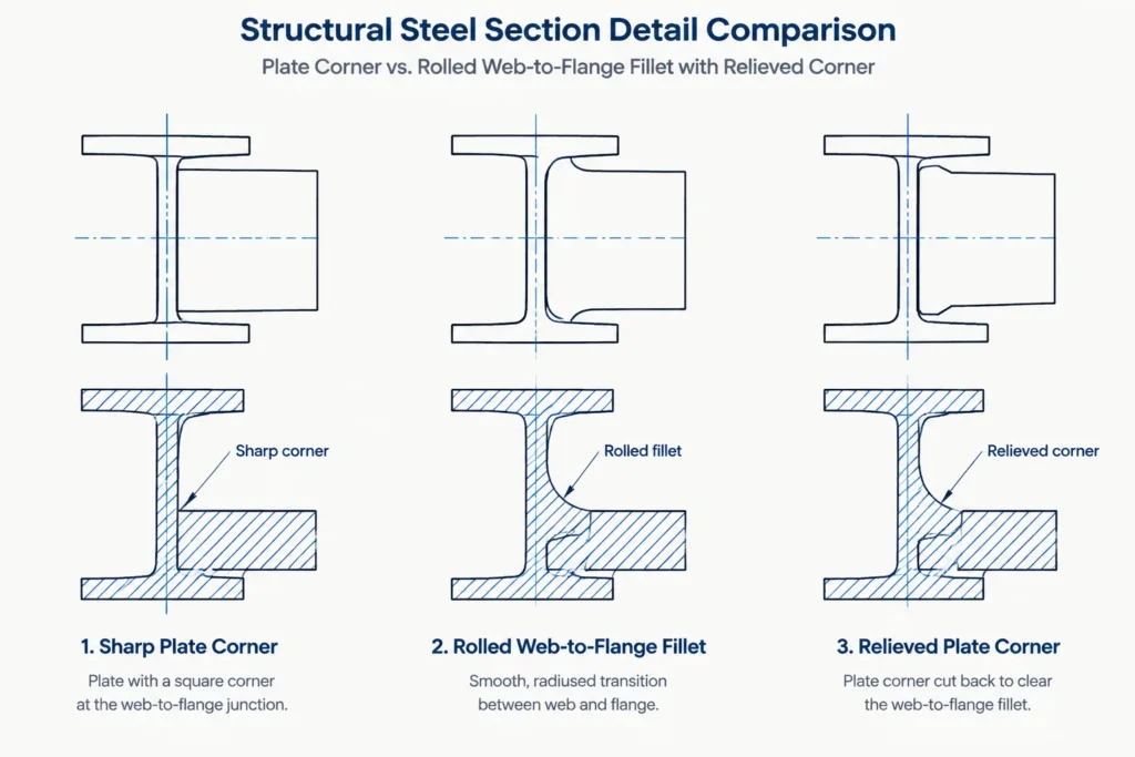
Rolled steel shapes are not assembled from perfectly square internal corners. The web-to-flange transition commonly includes a fillet created by the rolling process. Published shape data may provide dimensions that help identify the extent of this region, but the transition is not equivalent to an exact sharp-corner CAD profile.
If a plate edge is intended to contact the web while another edge approaches the flange, a sharp plate corner can intersect the rolled fillet before the straight edges reach their intended positions. Possible consequences include:
- A visible gap between the plate edge and the intended bearing or weld surface.
- A plate forced out of square during fit-up.
- Unplanned grinding of the rolled shape or detail plate.
- Incorrect weld access or an interrupted weld return.
- Assembly dimensions that no longer match the shop drawing.
- False clashes in a model or missed clashes in an oversimplified model.
A corner relief removes material from the detail plate so the plate can pass around the fillet while maintaining its specified position against the relevant straight surfaces.
Where corner reliefs commonly occur
Fillet interference should be considered whenever a detail part approaches the intersection of two surfaces on a rolled section. Common examples include:
- Transverse stiffeners fitted between W-shape flanges.
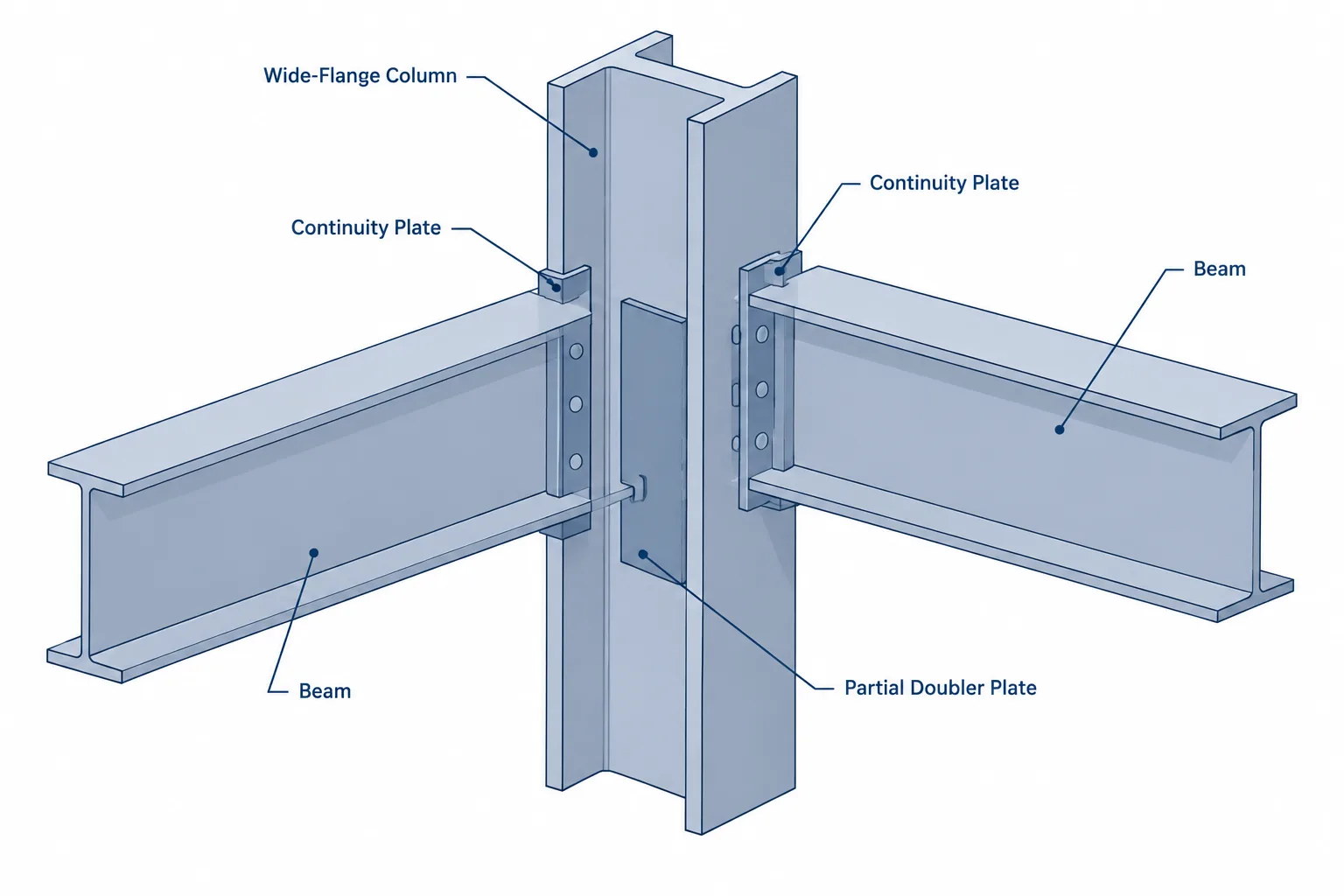
- Continuity plates meeting a column web and flanges.
- Connection plates located close to a beam flange.
- Bearing stiffeners extending through the available web depth.
- Cap, diaphragm, or closure plates fitted into rolled profiles.
- Plates attached to channels near the web-to-flange transition.
- Details added to structural tees near the stem-to-flange fillets.
Not every nearby plate needs a relief. A plate that intentionally stops clear of the transition may have sufficient clearance without one. The detailer must distinguish intentional clearance from a plate that is supposed to fit tightly against another surface.
Common relief geometry
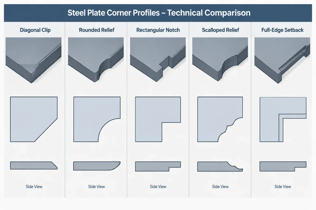
Several geometric forms can clear a rolled fillet. The appropriate form depends on shop practice, fabrication method, connection requirements, and weld layout.
| Relief form | Typical characteristic | Key coordination issue |
|---|---|---|
| Diagonal corner clip | A straight cut removes the sharp corner | The clip must clear the fillet without removing unnecessary plate area |
| Rounded relief | An arc or drilled profile forms a smooth internal transition | The radius and center location must be defined for fabrication |
| Rectangular notch | Two straight cuts create a stepped corner | Sharp re-entrant corners and weld termination require review |
| Scalloped relief | A curved cut wraps around the interference zone | The shape must be practical to cut and inspect |
| Plate setback | The entire plate edge stops before the fillet | The resulting gap must be compatible with the connection and weld intent |
A diagonal clip is simple to dimension and fabricate, but a generic clip should not be applied automatically to every condition. A rounded or scalloped relief may provide better access in some assemblies, while a deliberate setback may be preferable where contact with the adjacent surface is unnecessary.
Corner clips are not weld access holes
A plate corner clip and a weld access hole can appear similar in a section view, but they do not necessarily serve the same purpose. A corner clip primarily prevents geometric interference between a detail plate and a rolled fillet. A weld access hole is intended to provide access, continuity, or clearance for a weld operation in a specific joint configuration.
One opening may sometimes contribute to both objectives, but that should be established by the connection detail rather than assumed by the drafter. Weld access requirements can involve additional concerns such as weld sequencing, termination, inspection, stress flow, and surface preparation. A small fit-up clip should not be enlarged or relabeled as a weld access opening without engineering and fabrication coordination.
Using shape dimensions without treating the fillet as exact
Steel shape tables often include web, flange, and fillet-related dimensions that help detailers identify restricted zones. These values are useful for establishing conservative plate limits and checking whether a proposed part enters the transition region.
However, the rolled fillet should not automatically be reconstructed as a perfect mathematical arc from one table dimension. Published dimensions may define useful detailing boundaries rather than a complete manufacturing profile. Actual rolled geometry can also vary within applicable production tolerances.
For CAD work, the detailer should decide what the model is intended to accomplish:
- General arrangement model: A simplified section may be adequate if the plate includes intentional clearance.
- Connection coordination model: The fillet zone or a conservative clearance envelope should be represented well enough to detect interference.
- Fabrication detail: The plate relief must be explicitly dimensioned or otherwise unambiguously defined.
- CNC part geometry: The cut profile must match the approved detail and fabrication process, not merely a schematic model appearance.
Dimensioning the relief clearly
A corner clip should be controlled from stable plate datums. Depending on its form, this may require two linear dimensions, a radius and center location, or a defined cut profile. Avoid dimensions that depend on the theoretical edge of a rolled fillet, because that edge may not be a directly measurable shop datum.
The drawing should make clear:
- Which plate corners receive the relief.
- Whether similar corners are identical or individually defined.
- The orientation of an asymmetric clip.
- Whether the plate is tight to the web, flange, or another plate.
- Whether a shown gap is intentional.
- Where adjacent welds start, stop, or return.
- Whether the relief applies to the part geometry, the assembly preparation, or both.
Typical notes can reduce repeated dimensions, but only when the affected corners are genuinely equivalent. Mirrored assemblies, sloped flanges, skewed plates, and unequal plate setbacks can make apparently similar corners different.
Coordinate the relief with welds
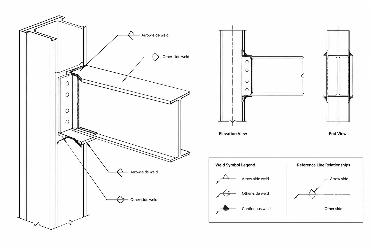
Removing a plate corner changes the available weld path. A weld shown continuously along a plate edge cannot remain continuous through material that has been clipped away. The drawing and model should agree about how the weld interacts with the relief.
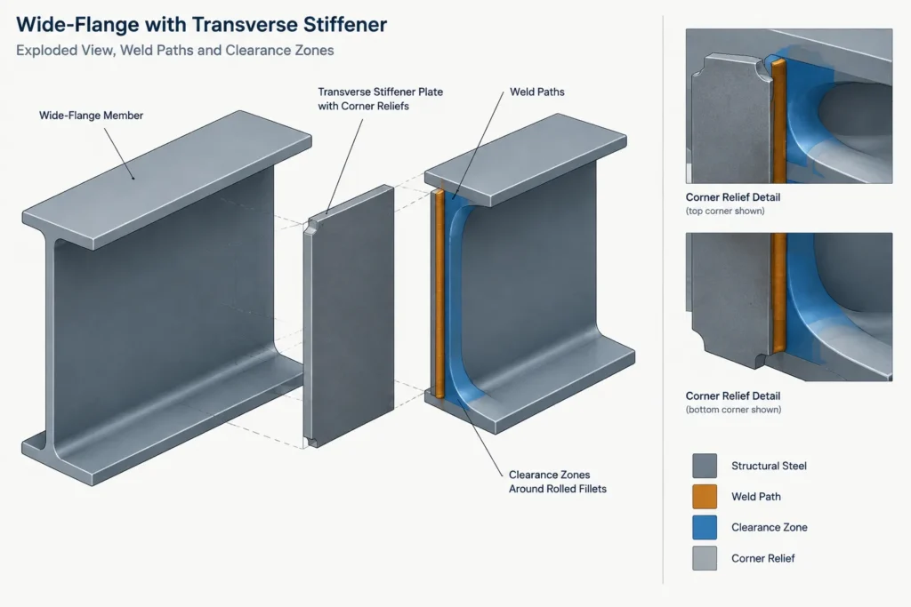
Questions to resolve include whether the weld terminates before the clip, follows the relieved edge, returns around a corner, or resumes on another edge. The answer is connection-specific and should come from the design and approved fabrication approach. Detailers should not extend welds through inaccessible regions simply to make the weld symbol or model look continuous.
Clearance for the welding process also matters. A relief that barely avoids solid interference may still leave inadequate access for electrode or gun positioning, cleaning, and inspection. Geometric clearance and workable fabrication access are related but separate checks.
A practical CAD and detailing workflow
- Place the member from a verified section reference. Confirm its orientation and the surfaces controlling the connection.
- Locate the plate from design datums. Use member centerlines, flange faces, web faces, work points, or specified offsets as appropriate.
- Identify transition-zone conflicts. Check every corner approaching a rolled fillet, including concealed and opposite-side conditions.
- Apply the intended relief type. Do not select a clip solely because it is available in a standard CAD library.
- Review remaining plate geometry. Confirm that the relief does not conflict with holes, welds, plate edges, or required load-transfer regions.
- Dimension from practical datums. Ensure the shop can create and verify the cut without measuring from an indistinct fillet tangent.
- Check the assembly in relevant views. A plan or elevation alone may hide interference that is obvious in section.
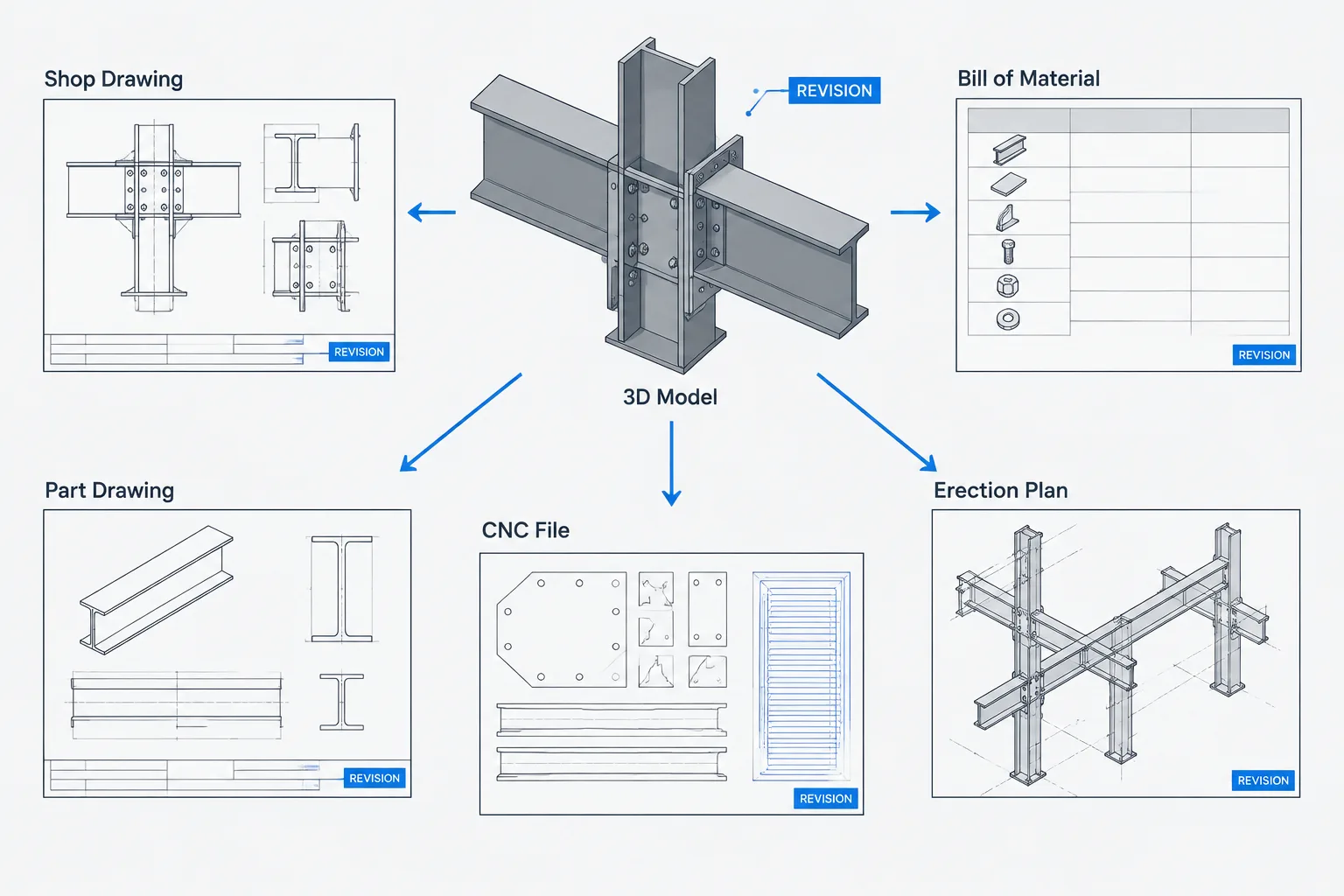
- Coordinate output files. The drawing, model, bill of material description, and CNC profile should represent the same part revision.
Checks when a member size changes
A plate relief that works for one rolled shape may not work for another, even when both shapes share a nominal depth. Web thickness, flange thickness, clear web depth, and fillet-related dimensions can change. Substituting a member can therefore alter both interference and available welding space.
After any shape change, recheck the plate position, clip geometry, weld access, hole clearances, and fit between flanges. Avoid carrying forward a previously used relief as an unchecked standard detail.
Detail for fit, fabrication, and design intent
Plate corner clips at steel fillets are small features with several jobs: they prevent interference, preserve intended plate alignment, support practical fabrication, and keep drawings consistent with real rolled geometry. The most reliable details use verified shape information, explicit plate datums, coordinated weld limits, and relief geometry that the shop can fabricate and inspect.
A CAD model can reveal the conflict, but it does not decide the correct solution. The final relief must remain consistent with the engineered connection, project requirements, fabricator practices, and the actual section being used.