Hollow structural section designations appear straightforward: outside depth or diameter, outside width where applicable, and wall thickness. The thickness shown in an HSS designation, however, does not necessarily serve every design, detailing, and fabrication purpose in the same way.
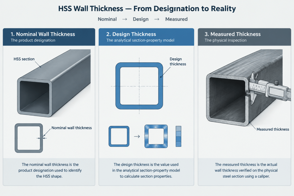
HSS nominal wall thickness identifies the listed product size. A design wall thickness may be used as the basis for structural properties, depending on the product specification and reference. The wall measured on a delivered member is a physical manufacturing result subject to permitted variation. Confusing these three ideas can produce mismatched calculations, inaccurate CAD geometry, and poorly fitting details.
Three wall-thickness concepts to keep separate
| Thickness concept | Primary purpose | Typical use |
|---|---|---|
| Nominal wall thickness | Identifies the HSS product and ordering size | Member designations, schedules, callouts, and material descriptions |
| Design wall thickness | Provides the thickness basis required by the applicable design method or reference | Section-property calculations, strength checks, and slenderness evaluations |
| Measured wall thickness | Describes the wall found on an actual manufactured member | Inspection, existing-condition surveys, fit-up investigations, and quality control |
These terms are related, but they are not interchangeable. A drawing normally calls out an HSS by its standard designation rather than replacing the nominal thickness with a design value. Conversely, an engineer should not assume that every tabulated section property was calculated directly from the nominal thickness printed in the designation.
What the thickness in an HSS designation represents
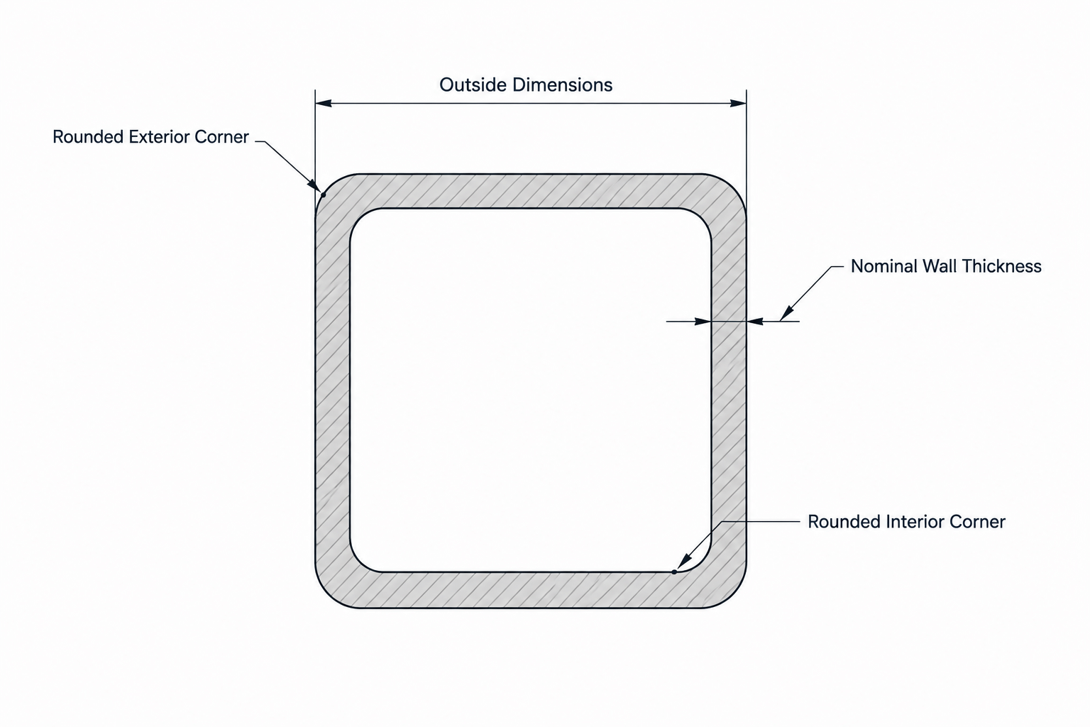
For rectangular and square HSS, the designation generally states the nominal outside dimensions followed by the nominal wall thickness. Round HSS designations generally state a nominal outside diameter and nominal wall thickness. The designation communicates the recognized product size; it is not a complete geometric inspection report.
The outside dimensions are especially important for coordination because connections, cladding supports, adjacent members, and architectural clearances commonly reference the exterior faces. The listed wall thickness helps identify the product, but it should not be treated as a promise that every point around every delivered section will measure exactly that value.
Manufacturing processes create permitted variation in wall thickness, outside dimensions, straightness, corner profile, and other geometric characteristics. The applicable product specification governs those tolerances. A shape table or CAD outline generally represents reference geometry, not the full envelope of acceptable manufactured variation.
Why a design wall thickness may differ
Some U.S. structural references use a design wall thickness that differs from nominal thickness for HSS produced under certain product specifications. This convention accounts for how the specification, manufacturing process, and permitted wall variation are treated in structural design. Other HSS product specifications may use a different relationship between nominal and design thickness.
The correct rule therefore cannot be selected from the HSS designation alone. Users must identify:
- The product specification required by the project documents.
- The basis stated in the governing design standard.
- The assumptions and notes accompanying the selected shape table.
- Whether imported data came from a current, compatible reference.
This distinction affects more than cross-sectional area. Any property derived from the section geometry may depend on the thickness basis, including moments of inertia, section moduli, radii of gyration, torsional properties, and width-to-thickness ratios. Recalculating properties from nominal CAD geometry can therefore disagree with a recognized table even when the designation is correct.
How to interpret HSS section-property tables
A reliable HSS table should be read as a coordinated dataset. The designation, dimensional columns, property columns, material specification assumptions, and table notes belong together. Copying a single row into a spreadsheet without retaining its source assumptions makes later verification difficult.
Check the notes before rebuilding properties
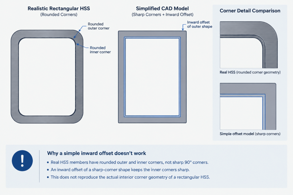
Before calculating area or inertia from listed outside dimensions and nominal wall thickness, determine which thickness the publisher used. Also determine how rounded corners were represented. Rectangular HSS is not a sharp-cornered outer rectangle with a smaller sharp-cornered rectangle removed from it. Rounded exterior and interior corners affect area and other properties.
A simplified sharp-corner model may be useful for visualization, preliminary coordination, or lightweight drafting. It should not automatically replace published section properties in engineering calculations.
Avoid mixing columns from different datasets
Two references can list the same HSS designation while using different formatting, rounding, specification assumptions, or property conventions. Do not combine dimensions from one source with properties from another unless their bases have been checked. A small unexplained discrepancy is a reason to review metadata, not to force the numbers to match.
Which thickness belongs on structural drawings?
Member callouts and schedules should normally preserve the recognized HSS designation required by the contract documents. Substituting an internal design thickness into the designation can create procurement confusion because that value may not identify the intended commercial product.
Design calculations may separately document the thickness basis used for section properties and limit-state checks. That calculation assumption does not necessarily need to appear in every member label, but it must remain traceable in the engineering record.
Detail drawings should add explicit dimensions when a connection depends on a physical surface or clearance. Examples include:
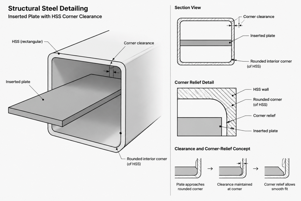
- Slots receiving plates inserted into an HSS wall.
- Through-plates or diaphragms that require controlled fit-up.
- Cap plates aligned to the outside faces.
- Attachments near rounded corners.
- Nested parts or sleeves involving inside clearance.
- Machined or tightly fitted components.
In these cases, relying only on the designation may leave the fabricator without enough information. The detail should communicate design intent while allowing fabrication methods and tolerances to be coordinated.
Modeling HSS wall thickness in CAD
The appropriate modeling method depends on the drawing purpose. A general arrangement model may need only an accurate exterior envelope. A connection model may need wall surfaces and corner regions. A fabrication model may require more specific geometry, but even a detailed solid remains an idealized representation unless it incorporates verified production information.
| Model purpose | Practical geometry approach |
|---|---|
| Plans and elevations | Prioritize correct outside dimensions, orientation, member centerlines, and elevations. |
| Typical sections | Show a representative hollow profile and identify it with the standard designation. |
| Connection coordination | Use a verified wall and corner basis; check clearances independently from the display outline. |
| Fabrication-sensitive fit | Coordinate with the fabricator and applicable product tolerances rather than trusting library geometry alone. |
Do not derive the inside profile by a simple offset
For square and rectangular HSS, subtracting twice the nominal wall thickness from each outside dimension produces only a simplified flat-to-flat estimate. It does not fully describe the interior because the corners have radii and the wall geometry transitions through those curved regions.
This matters when a plate approaches an inside corner. A plate that appears to fit within a sharp-corner CAD cavity may interfere with the actual rounded interior. Conversely, excessive clearance based on a crude model can weaken the intended positioning or make shop assembly harder. Corner-sensitive parts should be shaped, relieved, or dimensioned using verified project criteria.
Existing HSS requires field verification
An existing member cannot be fully identified from one wall measurement or an apparent outside dimension. Coatings, corrosion, access limitations, measurement location, and corner geometry can influence the observed value. Similar external sizes may also have different nominal wall thicknesses.
Record where and how measurements were taken. If structural evaluation depends on the result, the responsible professional should establish an appropriate investigation method. A database row or CAD block is useful for comparing possible designations, but it is not proof of the installed member’s specification, condition, or capacity.
A practical HSS thickness workflow
- Identify the product: Use the HSS designation and required material specification from the project documents.
- Select a compatible reference: Confirm that the shape table applies to that product basis.
- Read table notes: Determine whether dimensions are nominal and what thickness basis supports the properties.
- Preserve the designation: Do not rename the product using a design or measured thickness.
- Use published properties consistently: Avoid replacing them with properties from unverified CAD outlines.
- Model for purpose: Match the geometric detail to planning, coordination, connection, or fabrication needs.
- Check sensitive interfaces: Account for rounded corners and manufacturing tolerances where fit matters.
- Verify existing conditions: Treat field measurements as project-specific evidence rather than nominal database data.
The key distinction
Nominal thickness identifies the HSS product, design thickness supports the applicable structural calculation basis, and measured thickness describes a particular physical member at a particular location. Keeping those roles separate makes shape tables easier to interpret, CAD models more honest, and connection details less likely to depend on false precision.