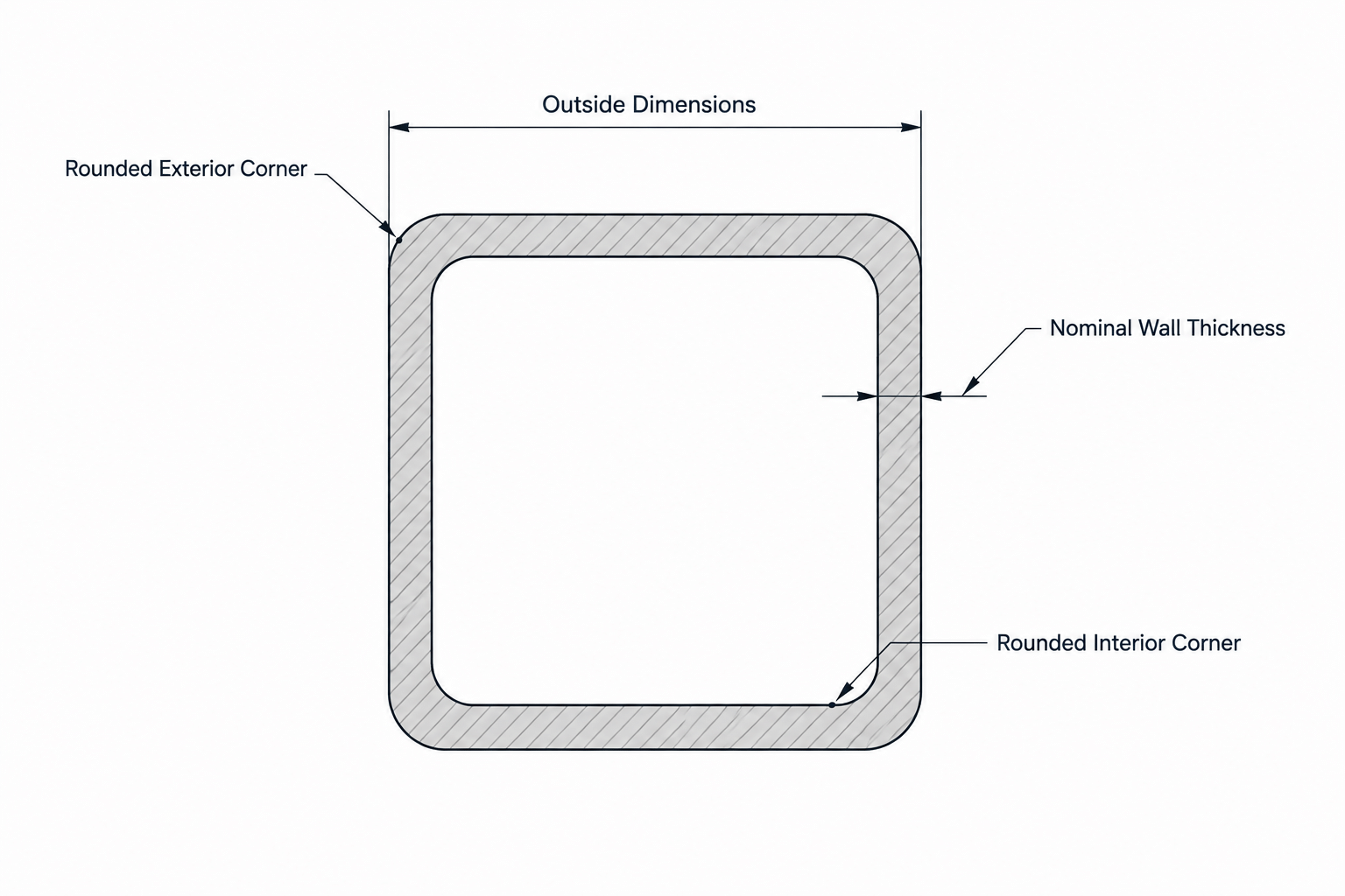
Tag: CAD modeling
-
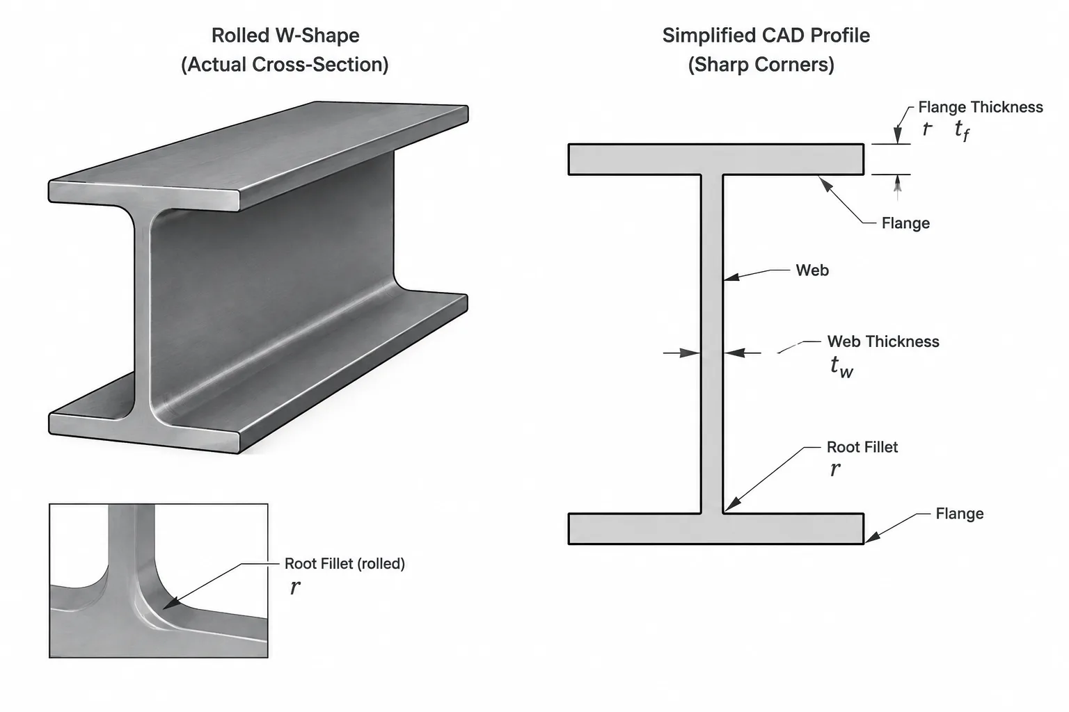
Web Thickness and Flange Thickness in Structural Steel Shapes: Reading tw and tf Correctly
Learn how to interpret tw and tf in steel shape tables, CAD profiles, connection details, and fit-up checks for W-shapes, channels, tees, and related sections.
Written by
-
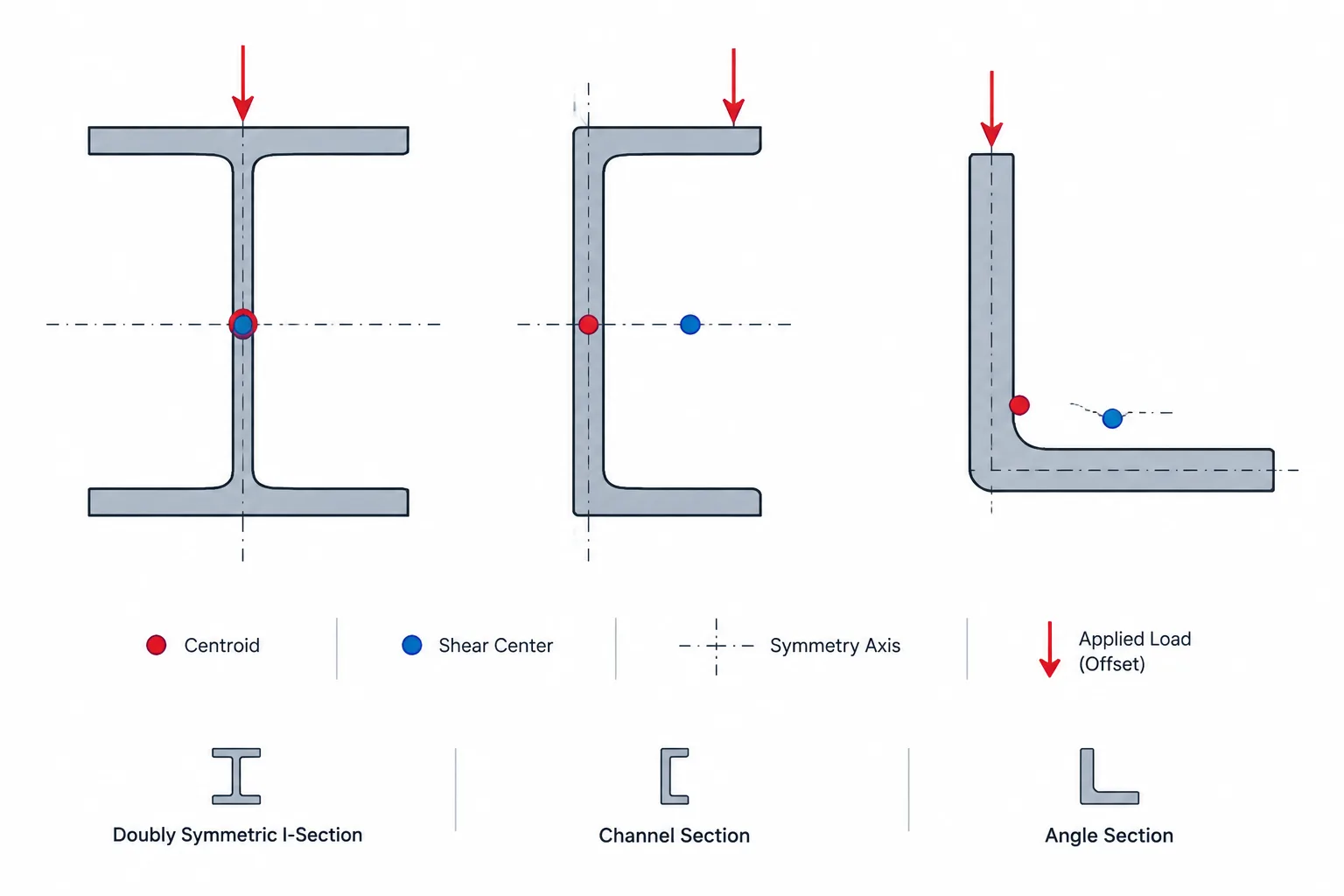
Shear Center vs. Centroid in Structural Steel Sections: Why Load Location Can Cause Twist
Learn how the shear center differs from the centroid in W-shapes, channels, angles, tees, and HSS, and why the distinction matters for loading, torsion, CAD modeling, and steel detailing.
Written by
-
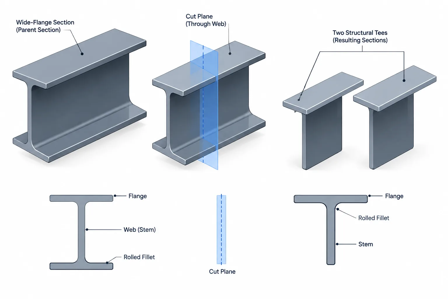
Split Structural Tees: Parent Shapes, Cut Lines, and Detailing Coordination
Learn how split structural tees relate to parent I-shapes, cutting methods, stem geometry, section properties, availability, and CAD detailing.
Written by
-
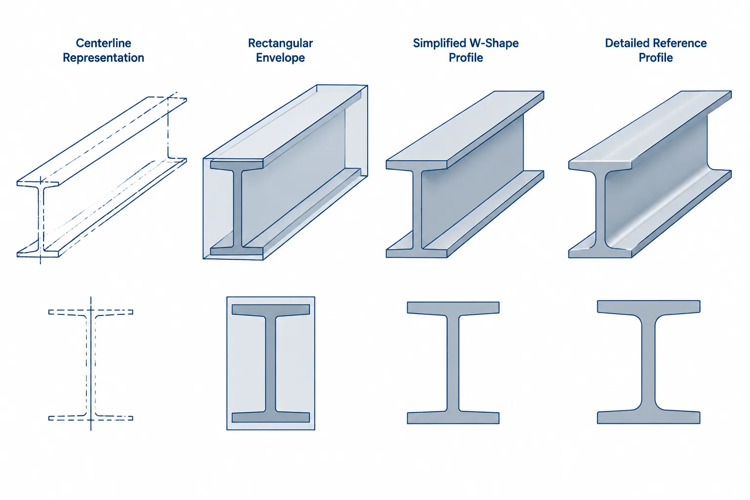
Exact vs. Simplified Steel Shape Geometry in CAD: Choosing the Right Level of Detail
Learn when to use single-line, simplified, detailed, or property-grade steel shape geometry in CAD models and structural steel drawings.
Written by
-
HSS Nominal Wall Thickness vs. Design Thickness: What Tables, Drawings, and CAD Models Mean
Learn how HSS nominal wall thickness differs from design thickness and measured wall, and how each should be handled in steel tables, drawings, and CAD models.
Written by