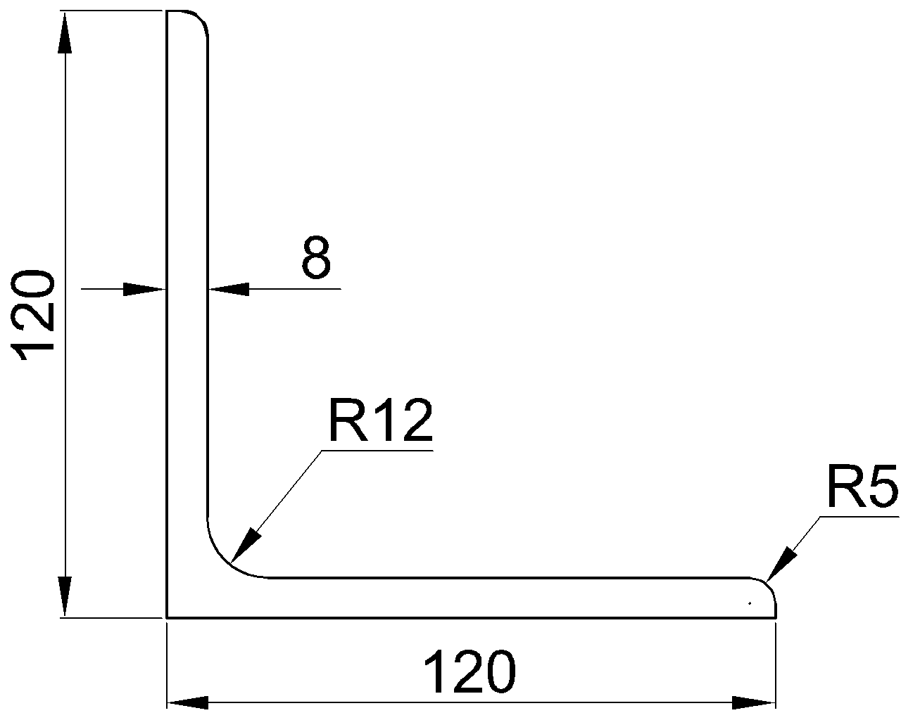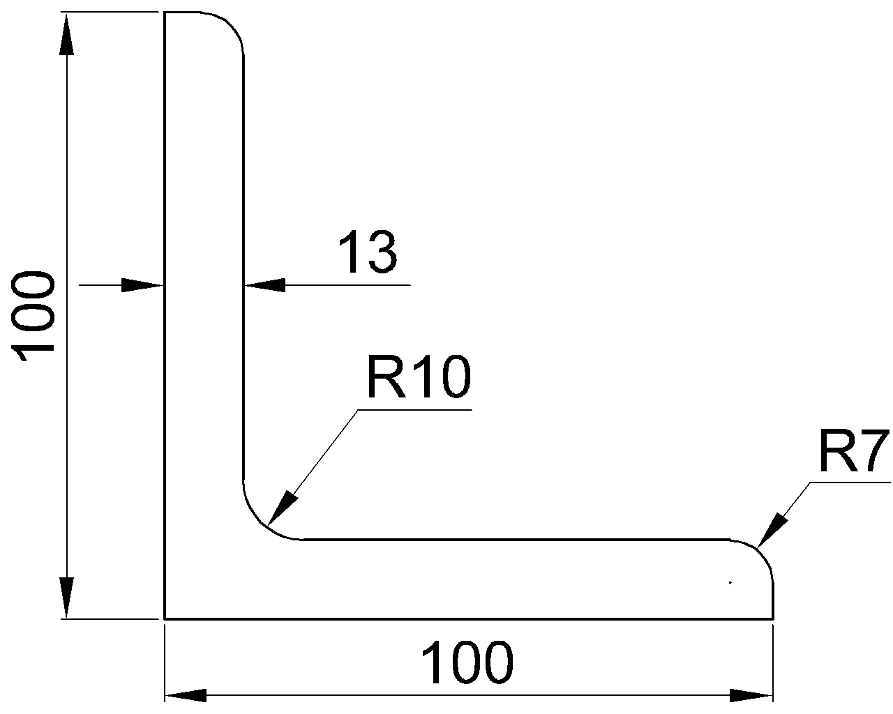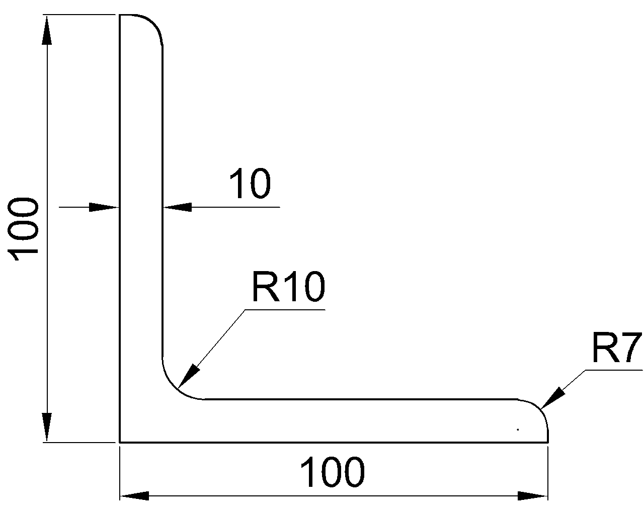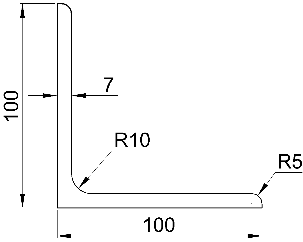
Pairs of channels or angles are often used when a single rolled shape does not provide the required geometry, connection access, or stability. Although these assemblies may look simple in a section view, the phrase back-to-back does not fully define them. A useful drawing must also establish orientation, clear spacing, connecting elements, member axis, and the faces from which dimensions are taken.
These details matter because changing the gap or reversing one component changes more than the appearance of the member. It can affect the built-up section’s centroid, moments of inertia, connection eccentricity, access for bolts or welds, and compatibility with plates or framing members. Drafters should therefore treat a paired-shape member as a defined assembly rather than as two casually mirrored CAD profiles.
What Back-to-Back Means for Channels
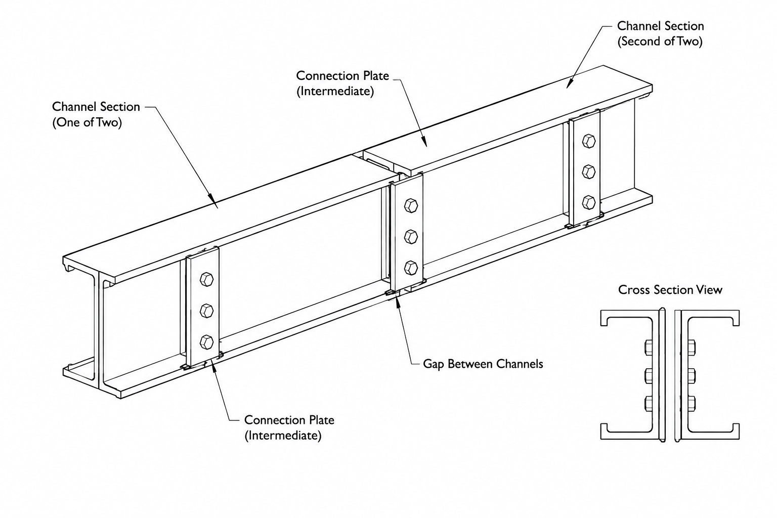
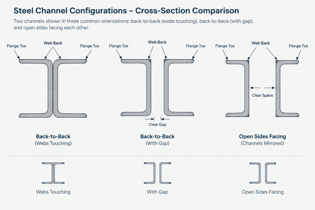
A channel has a web, two flanges, flange toes, and an outside surface commonly described as the back of the channel. In a typical back-to-back channel pair, the outside faces of the two webs face one another while the flanges project away from the center of the assembly.
The channel webs may be in direct contact, separated by a clear gap, or held apart by intermediate components. That distinction should never be inferred from the words “back-to-back” alone. Show the condition graphically and dimension it.
- Webs in contact: The channel backs are placed together, subject to actual rolled-shape geometry, tolerances, and the specified connection method.
- Separated webs: A defined space exists between the channel backs, often to accommodate gusset plates, connection plates, separators, or another framing element.
- Built-up assembly: The channels are connected at selected locations by bolts, welds, tie plates, diaphragms, or other detailed elements.
Channels arranged with their open sides facing one another are not described clearly by “back-to-back.” Terms such as toe-to-toe or face-to-face may be used informally, but a section view is the more reliable way to communicate the intended configuration.
Why Angles Require More Orientation Information
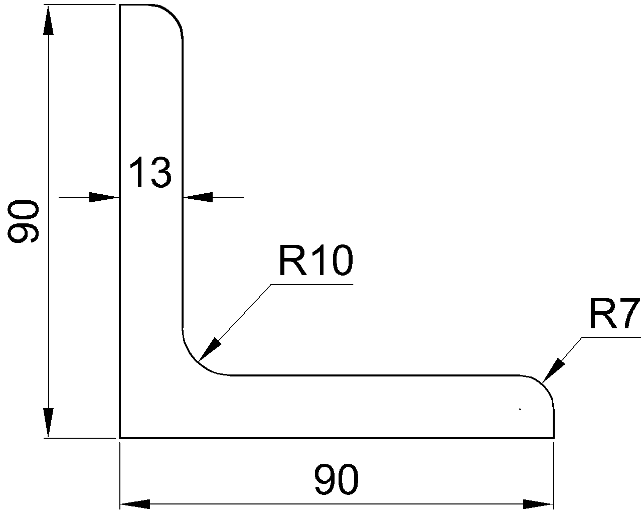
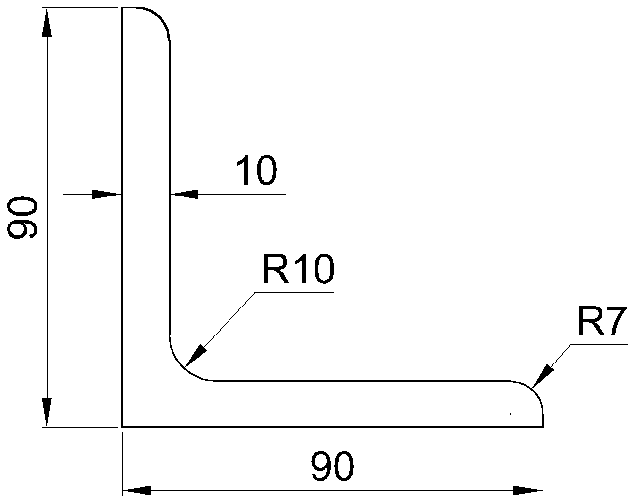
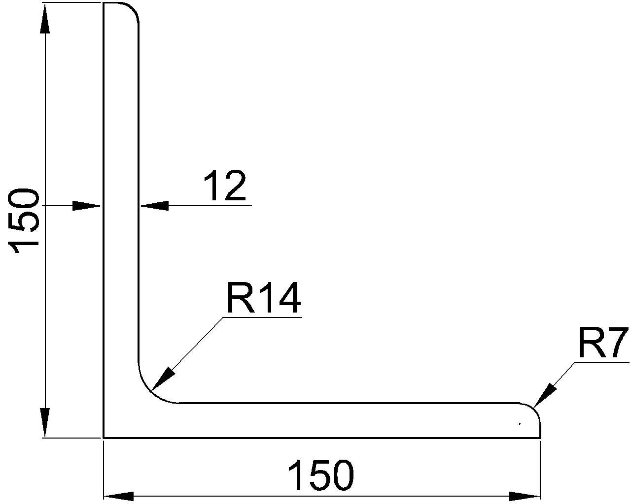
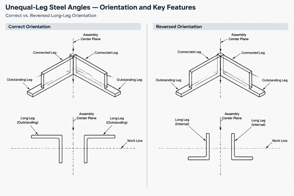
Back-to-back angle terminology is more ambiguous because an angle has two legs and no single web. A pair can use equal-leg or unequal-leg angles, and either leg may be selected as the connected leg. For unequal-leg angles, reversing the long and short legs can substantially change the overall width, connection geometry, and section-property axes.
An angle-pair detail should identify:
- The complete designation of each angle.
- Whether the long or short legs are back-to-back.
- Whether the connected legs touch or have a gap.
- The direction of the outstanding legs.
- The component placed between the angles, if any.
- The member work line or reference axis.
Plan, elevation, and section views should agree. A mirrored symbol in one view can unintentionally reverse an unequal-leg angle if the drafting model does not preserve a consistent local orientation.
Spacing Must Have an Explicit Reference
A spacing dimension is meaningful only when its extension lines identify the measured surfaces or reference planes. “Channel spacing” might mean clear distance between web backs, distance between component centerlines, or overall outside width. These values are not interchangeable.
| Dimension method | What it controls | Typical drafting concern |
|---|---|---|
| Clear distance between backs | Opening available for an inserted plate or framing element | Rolled fillets, plate thickness, tolerances, and erection fit may affect clearance |
| Component centerline spacing | Analytical location of the individual shapes | Shop personnel may still need a direct physical dimension |
| Overall outside width | Maximum assembly envelope | Does not by itself establish the internal gap |
| Spacer or plate thickness | Nominal separation created by an intermediate part | Must be coordinated with welds, bolts, and fit-up requirements |
Where fit is important, show both the functional dimension and the assembly arrangement. Do not rely on scaling the drawing. Also avoid dimensioning simultaneously to the gap, component centerlines, and overall width unless the dimensions are clearly identified as reference or are otherwise coordinated. Redundant controlling dimensions can conflict after revisions.
A Pair Is Not Automatically a Fully Composite Member
Two shapes drawn beside each other do not automatically behave as one continuous section. Their structural interaction depends on how forces are transferred between them. Connection type, connector spacing, intermediate plates, member length, loading, and the required stability behavior all matter.
The structural design should define the necessary bolts, welds, tie plates, separators, or other connectors. A drafter should not select connector size or spacing merely to make the assembly look complete. Likewise, a CAD section assembled from two shape outlines does not establish that the pair has adequate built-up action.
Detailing should answer practical fabrication questions: Are the channels joined through their webs, through tie plates at the flanges, or by another arrangement? Are separators continuous or intermittent? Can the specified welds be placed and inspected? Is there tool access for bolts? Can coatings reach the space between components? These questions may require coordination with the engineer and fabricator rather than an assumed generic detail.
Section Properties of Paired Shapes
Database properties for a single channel or angle generally describe that individual rolled shape about its own published axes. They should not be copied directly into a paired-member calculation as though the pair were a single catalog shape.
For a built-up pair, the combined centroid must be established from the areas and locations of the components. Moments of inertia then depend on both each shape’s own property and its offset from the assembly axis. Increasing the separation can increase an assembly property about one axis because the component areas are farther from that axis. It may also increase connection demands or produce a less convenient overall width.
A symmetric pair can place the assembly centroid on its center plane, but symmetry should be verified from the actual geometry. Unequal angles, dissimilar shapes, offset plates, or unequal spacing can move the centroid away from the visually obvious center. Principal axes may also require attention for an unsymmetric assembly.
Channels introduce an additional concern: the shear center of an individual channel does not generally coincide with its centroid. A properly arranged symmetric pair may reduce some eccentric effects, but that outcome depends on orientation and load application. The design model, not the appearance of the section view, should govern.
Connection Plates and Clearances
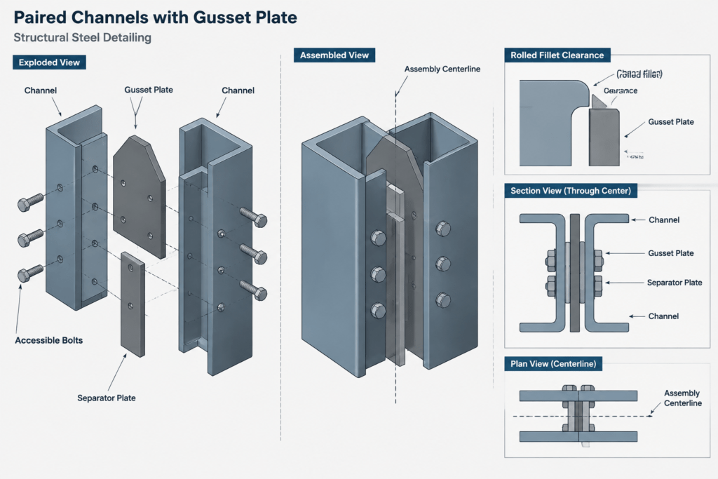
Paired channels and angles are frequently separated to receive a gusset plate. The nominal plate thickness alone is not enough to confirm a workable fit. The detail may also need to account for rolling tolerances, surface condition, coatings, welds, bolt heads or nuts, and the rounded regions near flange-to-web or leg intersections.
A plate should not be drawn as though it can extend through a rolled fillet or angle heel without a deliberate clearance solution. Depending on the engineered detail, the plate may stop short, receive a shaped corner, use a clearance cut, or be positioned away from the fillet region. Do not alter a connection plate or rolled member simply to eliminate a CAD overlap; coordinate the required geometry.
For bolted assemblies, check access from both sides and confirm that adjacent outstanding legs or flanges do not obstruct installation. For welded assemblies, show which component is welded and where the weld can physically be made. A weld symbol attached to the pair’s centerline can be ambiguous if it does not identify the connected surfaces.
Recommended CAD and Drawing Workflow
- Insert verified component profiles. Use the correct channel or angle designation and retain its actual rolled-shape orientation.
- Assign a local origin. Choose the assembly center plane, work line, or another documented reference rather than an arbitrary profile corner.
- Orient the first component. Confirm web direction for a channel and connected-leg selection for an angle.
- Mirror or place the second component carefully. Verify the result instead of assuming a mirror command produces the intended unequal-angle orientation.
- Apply the controlling spacing. Use the defined clear gap, centerline spacing, or separator thickness from the project documents.
- Add connection components. Model plates, separators, bolts, and weld extents only from coordinated information.
- Check multiple views. Review section, plan, elevation, and any end view for consistent orientation.
- Annotate the assembly. Include shape designations, quantity, spacing reference, work line, and references to connection details.
- Perform an interference review. Look for conflicts at fillets, bolt access zones, weld locations, copes, plates, and intersecting members.
Common Drawing Errors
- Calling a pair back-to-back without showing whether the components touch.
- Using a center-to-center dimension where fabrication requires a clear opening.
- Reversing the long and short legs of an unequal angle in another view.
- Assuming twice the single-shape section property represents the spaced pair.
- Placing a gusset or separator through a rolled fillet region.
- Adding generic stitch welds or bolts without design information.
- Dimensioning from an idealized sharp corner instead of a usable reference face.
- Showing bolts where tools cannot reach the head or nut.
- Failing to distinguish the assembly centerline from either component’s centroidal axis.
A Clear Assembly Beats Informal Terminology
Back-to-back channels and angles are best communicated through a combination of designation, section view, orientation notes, and unambiguous dimensions. The drawing should establish what the components are, which faces oppose one another, how far apart they are, and how they are connected.
Shape databases and CAD profiles provide the geometry of the individual rolled sections. They do not determine the structural behavior, connection requirements, or fabrication clearances of the completed pair. Those items must be coordinated with the project design and verified before a detail is issued for fabrication.