Framing a steel beam into a hollow structural section column presents a different detailing problem from framing into a W-shape column. An HSS column has no exposed flange or accessible web. Instead, the connection must transfer forces through a closed wall whose exterior face may also serve as an architectural surface, a cladding datum, or the reference for several framing elevations.
Successful beam-to-HSS-column detailing begins with more than selecting a connection symbol. The drafter must understand which face controls the beam location, how the connection interacts with the HSS wall, whether work must occur inside the closed section, and how fabrication and erection access affect the proposed geometry. Final connection selection, strength, and required reinforcement remain engineering decisions, but clear geometric coordination can prevent many avoidable conflicts.
Start with the column reference system
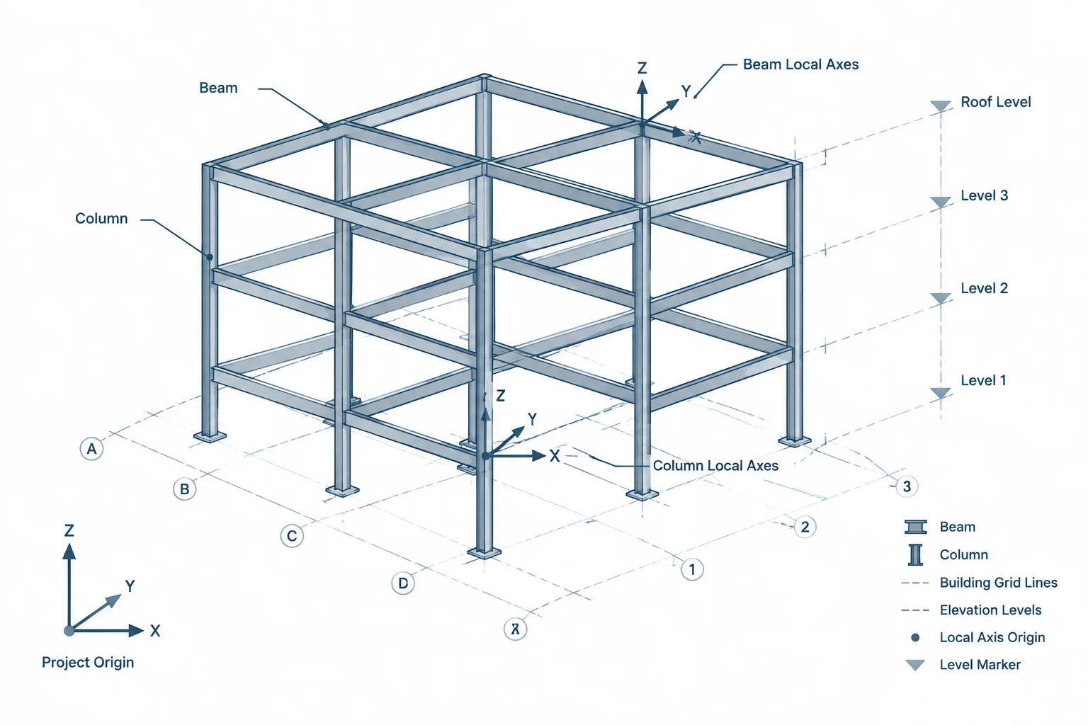
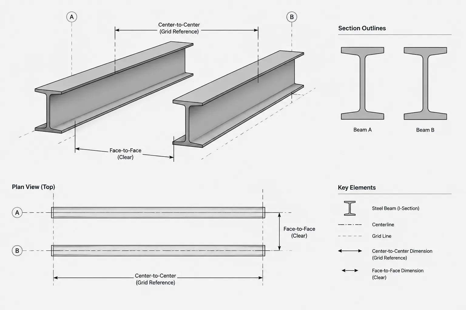
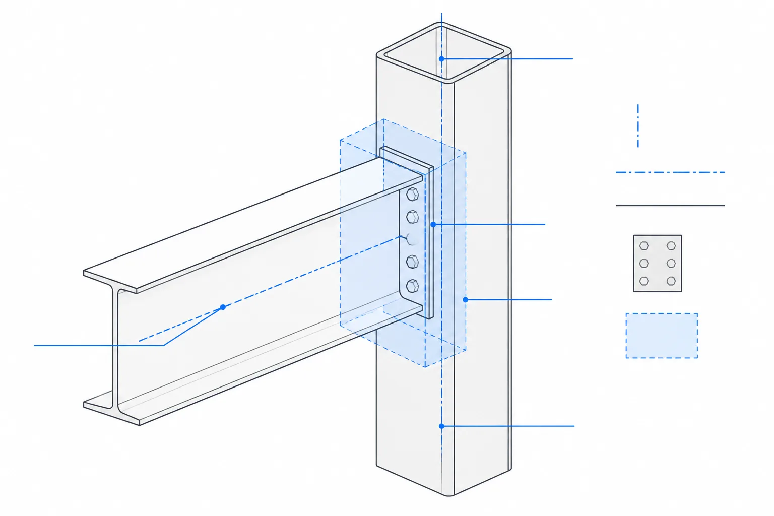
An HSS column is commonly located by its centerline at structural grid intersections. Beam end geometry, however, is usually controlled by the actual outside face of the column. Those references are related, but they are not interchangeable.
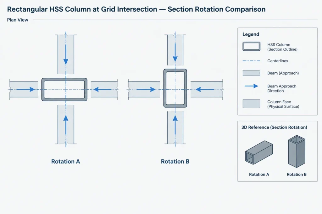
For square HSS, the nominal half-width provides a convenient conceptual offset from the member centerline to a face. Rectangular HSS requires additional care because rotating the section changes which overall dimension lies in each plan direction. A model can have the correct column centerline and still place a beam against the wrong face if the section rotation is incorrect.
At each framing level, identify:
- The structural grid and HSS member centerlines.
- The orientation of square or rectangular faces in plan.
- The beam work line and top-of-steel elevation.
- The controlling column face for the beam setback.
- Any architectural offsets, finishes, or fireproofing zones that must remain clear.
- The vertical zone available for connection plates, welds, bolts, and erection access.
Do not rely solely on a generic beam setback measured from the grid. If the HSS size or orientation changes, the face location changes even when the column centerline remains fixed.
Recognize the principal connection concepts
Several connection arrangements can be used at an HSS column. Their suitability depends on the required force transfer, the HSS wall behavior, fabrication sequence, access, and project-specific design. The following categories help drafters recognize the geometric implications without treating one detail as universally applicable.
| Connection concept | Typical geometric feature | Primary detailing concern |
|---|---|---|
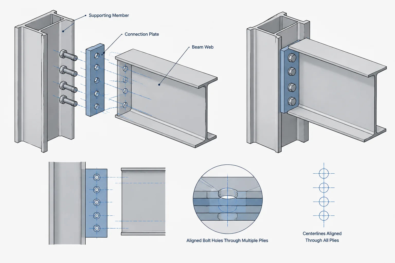
| Plate welded to the HSS face | An external plate receives the beam web or end connection | Plate projection, HSS wall effects, weld access, and beam-end clearance |
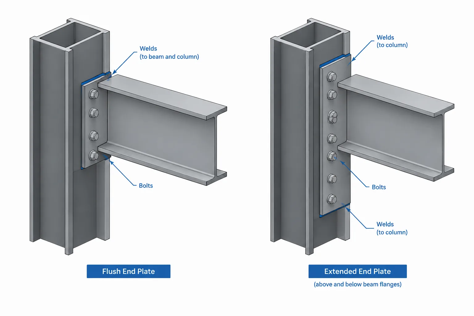
| End plate at the beam | A plate at the beam end meets the HSS face or an attached element | Bolt or weld arrangement, erection sequence, and wrench access |
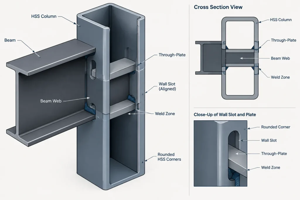
| Through-plate | A plate passes through slots or openings in opposing HSS walls | Slot geometry, internal fit, weld sequence, and alignment through the section |
| Knife plate | A projecting plate engages a beam web, HSS brace, or slotted member | Plate centering, slot clearance, weld termination, and erection fit |
| Cap, diaphragm, or collar arrangement | External or internal components distribute forces around the HSS | Continuity around corners, intersecting beams, fabrication sequence, and congestion |
A connection sketched as a simple plate in elevation may be much more complicated in section. The HSS face, adjacent corner radii, opposite wall, and closed interior all influence fabrication. Detail at least one section that reveals the complete load-transfer geometry rather than showing only the visible plate outline.
Treat the HSS wall as part of the connection
The wall of an HSS column is not merely a background surface for attaching a plate. Concentrated forces introduced by a beam connection may cause local behavior in the connected face or adjacent walls. The connection engineer may need to evaluate yielding, deformation, punching-type behavior, weld transfer, or other applicable limit states. Reinforcement or a different connection concept may be required.
For detailing purposes, this means that plate dimensions should not be copied from a W-column connection without review. A plate that works geometrically on a column flange may not distribute force appropriately into an HSS wall. Likewise, increasing a plate footprint can create new conflicts with HSS corners, nearby framing, or architectural clearance.
When connection design is incomplete, show the connection zone and identify unresolved requirements rather than filling the model with an assumed final detail. Useful coordination questions include whether reinforcement is external or internal, whether opposite faces are involved, and whether the HSS must be cut before the column assembly is closed.
Account for rounded corners and usable face width
Square and rectangular HSS have rounded corners rather than sharp theoretical intersections between faces. The central flat portion of a face is therefore less than the overall outside width. This matters when laying out wide plates, weld returns, bolt lines, or multiple connections meeting adjacent faces.
A simplified sharp-corner CAD rectangle may be adequate for early framing plans, but it can misrepresent the usable attachment region. For fabrication details, use verified section geometry or clearly maintain clearance from the corner transition. Do not infer an exact corner radius from a schematic model.
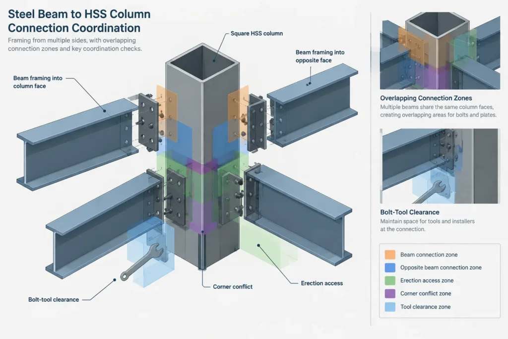
Connections on adjacent HSS faces also need a three-dimensional check. Plates that look separate in two independent elevations may overlap near the corner. Welds, backing elements, bolt heads, or beam flanges can compete for the same space even when each individual view appears acceptable.
Coordinate the beam end and erection path
The nominal gap between a beam end and the HSS face is only one part of erection fit. The beam must be moved into position, temporarily supported, and connected using a realistic installation path. A plate projecting from the column can obstruct beam rotation or prevent the member from dropping vertically between adjacent elements.
Review the following conditions in the model and shop details:
- Beam flange clearance from the HSS face and attached plates.
- Web alignment with tabs, knife plates, or connection centerlines.
- Access for bolts, nuts, washers, welding tools, and inspection.
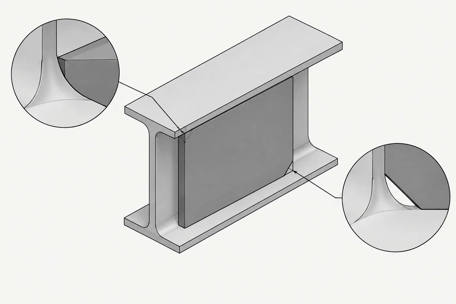
- Interference between connection plates and the beam root fillets.
- Clearance for skewed or sloped beam end geometry.
- The ability to install the beam after nearby columns, beams, deck, or braces are present.
- Temporary stability needs before the final connection is completed.
Where beams frame into opposite faces at the same elevation, do not examine each connection in isolation. Through-plates, internal hardware, weld zones, and heat input may affect both sides. Opposing beam elevations that appear identical may still require a coordinated fabrication sequence.
Show openings and internal work explicitly
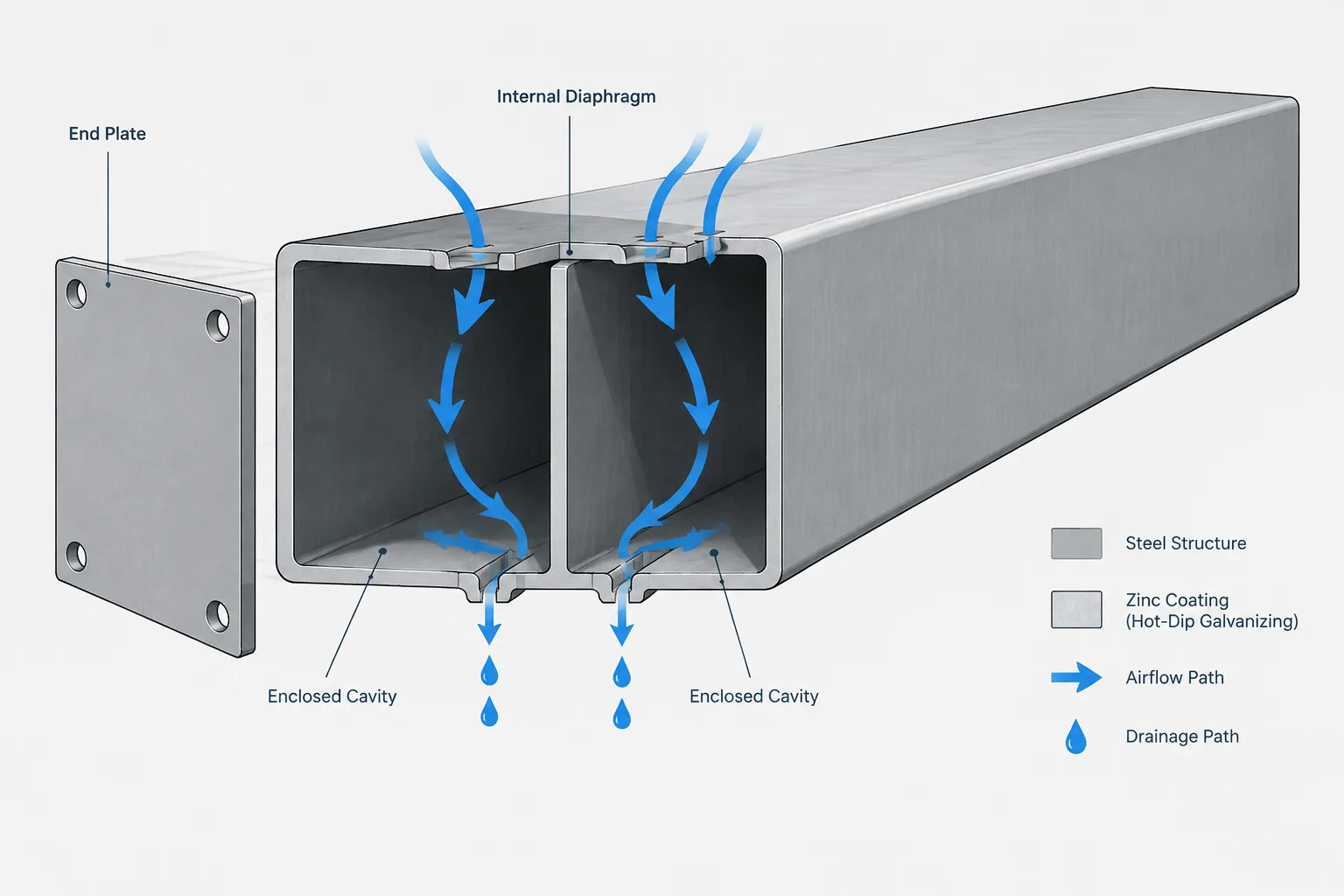
Any connection requiring access to the inside of an HSS deserves special attention. Internal plates, hidden welds, backing components, and nuts cannot be assumed to remain accessible after the section is assembled. The drawing set should communicate how the fabricator reaches the work and when openings are closed.
If an access opening is proposed, its location and final treatment must be coordinated with the connection engineer and fabricator. The opening can affect the HSS wall, interfere with another connection, and alter the appearance or coating requirements of the finished column. A generic note such as “provide access as required” may not adequately define the intended result.
For through-plates, include views showing the plate path through both walls. Confirm that slots align in the same coordinate system and that the plate does not unintentionally intersect internal reinforcement or another through-connection.
Use a face-based CAD workflow
A reliable modeling workflow keeps the analytical member line, physical HSS faces, and connection datums distinct. Begin with the verified HSS profile and section rotation. Establish named or clearly identifiable reference planes at the column faces, then locate beam ends and connection components from the appropriate face.
Recommended sequence
- Place the HSS column by the project grid and elevation references.
- Verify which section dimension is aligned with each global direction.
- Create or identify the physical face receiving the beam.
- Set the beam work line and top-of-steel condition.
- Apply the reviewed beam setback from the controlling face, not merely from the grid.
- Model the proposed connection envelope before adding detailed holes and weld geometry.
- Check adjacent and opposite faces in three dimensions.
- Generate sections that expose the HSS wall, plate, beam end, and access zone.
- After connection review, update the model, shop details, material list, and CNC information together.
If a preliminary model uses simplified HSS corners or symbolic connection plates, label that level of development internally so the geometry is not mistaken for fabrication-ready information.
Drawing information that reduces ambiguity
Beam-to-HSS-column details should make controlling references easy to identify. Depending on the connection, useful information may include the HSS orientation, beam elevation, face-to-end relationship, plate location, hole datums, weld location, and whether components are centered on the beam web or offset from it.
Use sections and plans together. An elevation communicates vertical relationships, while a plan or horizontal section confirms the active HSS face and plate projection. Where several beams meet one column, an isometric shop view can help explain the assembly, but it should supplement rather than replace dimensioned orthographic views.
Final coordination checklist
- Is the HSS size and rectangular-section rotation verified?
- Is the controlling column face identified independently of the grid line?
- Does the beam end reflect the actual connection and erection clearance?
- Are rounded corners considered where plates approach face edges?
- Has the HSS wall been included in the connection-engineering review?
- Are connections on adjacent and opposite faces coordinated?
- Can bolts, welds, and internal components actually be installed?
- Are through-slots and access openings shown in all necessary views?
- Does the fabrication sequence preserve access to internal work?
- Have model, drawing, material, and machine-data revisions been synchronized?
The central detailing lesson is simple: an HSS column connection is governed by physical faces and closed-section constraints, not just by intersecting member centerlines. Establishing reliable face datums, modeling the complete connection zone, and reviewing access in three dimensions produces clearer drawings and gives the engineer and fabricator a better basis for resolving the final connection.