Flange gage is a small dimension with a large influence on structural steel connection geometry. In a typical bolted W-shape flange connection, it locates the longitudinal bolt lines on opposite sides of the web. That placement affects hole clearance near the web-to-flange fillets, access for installation tools, edge distances on connected plates, and whether a detail remains usable after a member substitution.
A published or commonly used workable gage is a useful starting point, but it is not a complete connection design. Drafters and designers must evaluate the actual shape, hole type, fastener arrangement, connected material, fabrication method, and required access. This guide explains the terminology and presents a practical checking workflow without prescribing a universal gage.
What is flange gage?
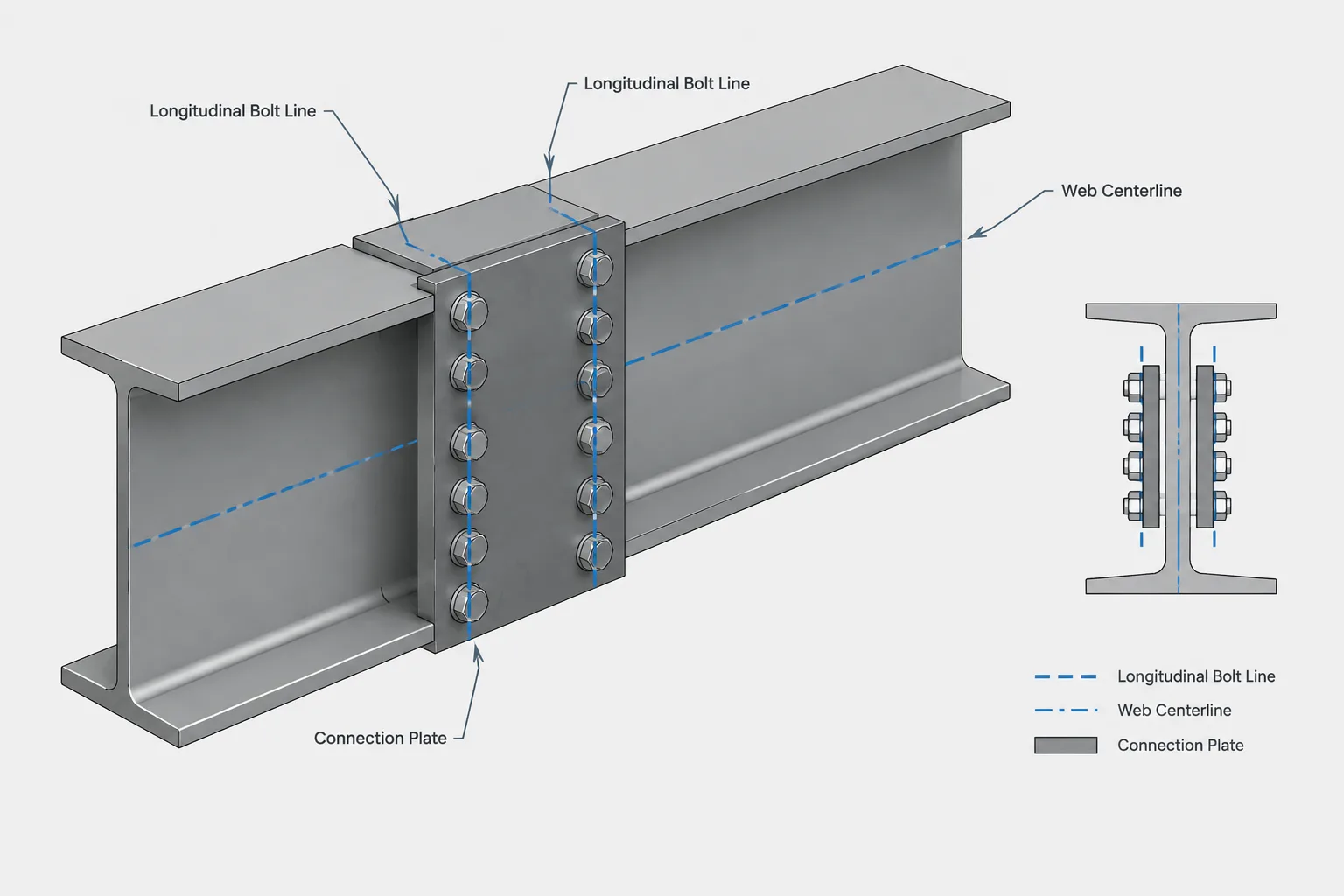
In a conventional W-shape connection, flange gage is the transverse distance between bolt lines placed on opposite sides of the member web. The dimension is measured across the flange, generally perpendicular to the member’s longitudinal axis.
If the bolt pattern is symmetric about the web centerline, each bolt line is located one-half of the total gage from that centerline. Showing only the total gage can make symmetry clear, while dimensioning each bolt line from a verified reference may be more useful for fabrication. The drawing method should match the shop’s conventions and avoid redundant dimensions that can conflict.
The term describes bolt-line spacing, not the flange width and not the distance from a bolt line to a flange edge. Those related dimensions must be checked separately.
Gage, pitch, edge distance, and end distance
Connection layouts become easier to review when each dimension is assigned the correct direction and purpose.
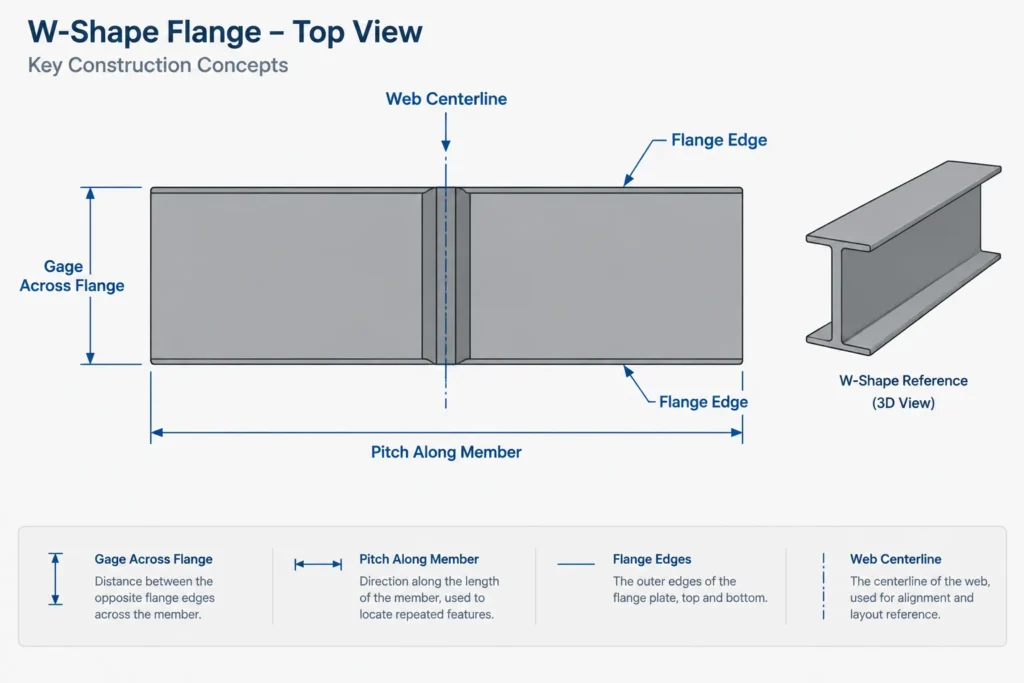
| Term | What it locates | Typical direction on a flange |
|---|---|---|
| Gage | Spacing between adjacent longitudinal bolt lines | Across the flange |
| Pitch | Spacing between successive bolts in the same line | Along the member |
| Edge distance | Distance from a hole center to a nearby material edge | Often across a flange or plate |
| End distance | Distance from a hole center to the end of a member or plate | Along the member |
A rectangular bolt group may therefore require both gage and pitch dimensions. Its location may also require an end setback, connection work point, or reference to a plate edge. One dimension should not be expected to communicate all of these relationships.
What a workable gage means
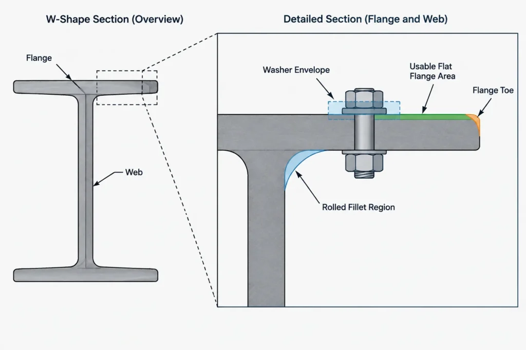
A workable gage is a practical bolt-line spacing associated with a rolled shape or connection arrangement. It is intended to place holes where fabrication and bolt installation are generally feasible, particularly with respect to the web, flange edges, and rolled fillet region.
It should not be interpreted as the only permitted gage or as proof that every proposed connection fits. A workable gage does not automatically verify:
- Required hole edge distances in the W-shape or connected plate
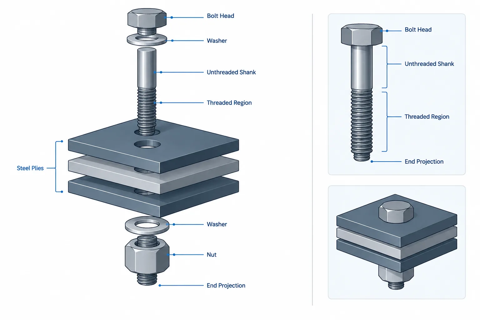
- Clearance for bolt heads, nuts, washers, or installation tools
- Interaction with the web-to-flange fillet
- Fit of splice plates, cap plates, stiffeners, or other connection components
- Effects of oversized or slotted holes
- Structural adequacy of the flange or bolt group
- Fabrication tolerances and erection access
Published shape information and project criteria should be consulted for the member being detailed. Do not transfer a gage from a visually similar shape without checking it.
Why the rolled fillet matters
The inside face of a W-shape flange does not meet the web at a sharp corner. A rolled transition occupies this region. A bolt, washer, plate, or drill path placed too close to the web may interfere with that transition even when a simplified CAD outline appears clear.
This is one reason a workable gage is not based solely on flange width. The detail must account for the usable flat portion of the flange and for the space required by the complete fastener assembly. A washer or tool envelope may govern before the hole itself appears to clash.
Simplified section blocks often omit or idealize fillets. They are useful for layouts, but they should not be treated as exact fabrication geometry unless their source and level of detail have been verified.
Flange edge checks
Moving bolt lines away from the web may improve clearance at the rolled fillet, but it simultaneously moves them closer to the flange toes. This creates a basic detailing balance: the gage must be wide enough for inside clearance without becoming too wide for the available flange.
For a centered two-line pattern, the nominal distance from either bolt line to its corresponding flange edge can be derived from the actual flange width and gage. That geometric result is only a starting point. The applicable edge-distance criteria, hole geometry, edge condition, tolerances, and engineering requirements still need to be evaluated.
Do not assume both sides have equal usable space merely because the W-shape is nominally symmetric. Plates may be offset, adjacent framing may restrict access, or the connection may intentionally use an asymmetric bolt arrangement.
Connected plates can control the layout
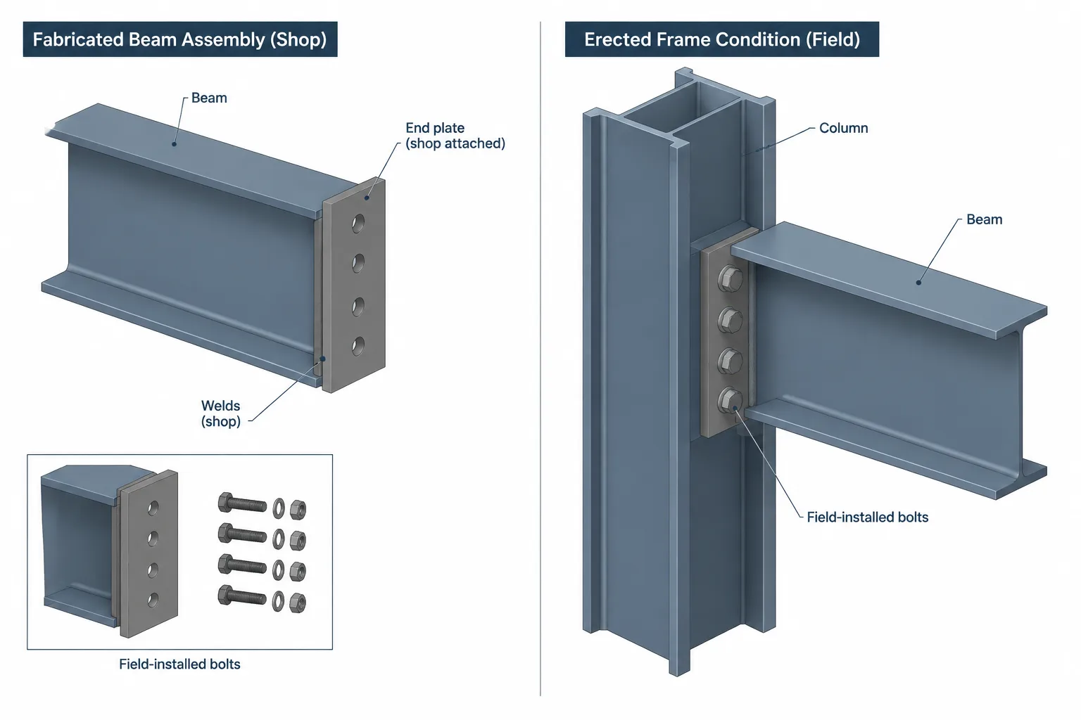
A bolt pattern that fits the beam or column flange may not fit the flange plate, splice plate, bracket, or other connected element. Plate width must accommodate the hole pattern and required material beyond the holes. If the plate is shop welded to another component, weld access and weld termination may further limit the available area.
When flange forces are transferred through bolted plates, the gage also influences the plate’s load path and connection behavior. Changing gage is therefore not just a drafting cleanup. Any change that affects the engineered arrangement should be returned to the responsible designer for review.
Single-line and multi-line bolt patterns
Single centered bolt line
A single line may be located on the member centerline in some connection types. In that arrangement, there is no two-line flange gage, although pitch, end distance, and clearances remain relevant. The web or rolled transition may make a centered line impractical for certain flange details.
Two symmetric bolt lines
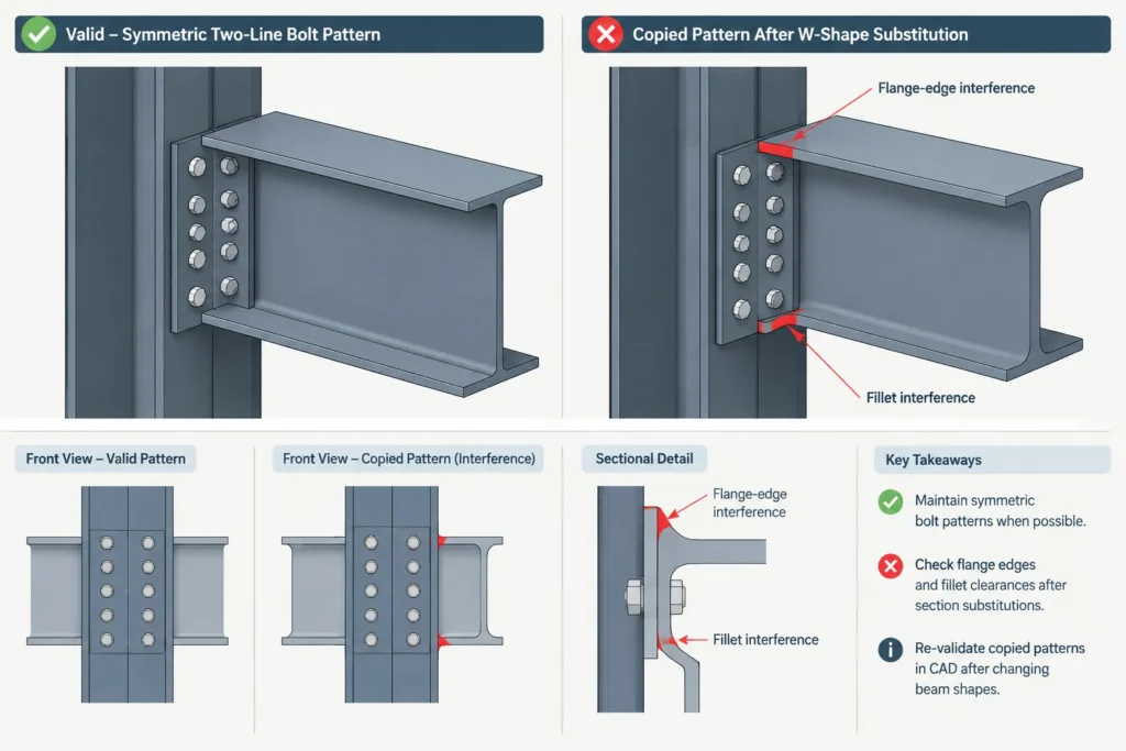
This is the arrangement most commonly associated with a W-shape flange gage. The web centerline is the natural reference, and the total gage spans the two lines.
More than two bolt lines
Wide flanges or heavily configured connections may use additional lines. A single overall gage is then insufficient. The drawing should define each transverse spacing or clearly identify a repeated spacing without leaving the outer lines ambiguous.
Asymmetric patterns
Interferences or connection geometry may require unequal offsets from the web. In that case, avoid implying symmetry with a centered total-gage dimension. Locate each bolt line from a stable datum and make the intentional offset unmistakable.
Member substitutions require a fresh check
A replacement W-shape may share a nominal depth with the original member while having a different flange width, flange thickness, web thickness, or rolled transition geometry. Retaining the old bolt pattern can produce flange-edge or fillet conflicts.
When a shape changes, recheck the actual flange dimensions, available flat region, bolt and washer envelopes, connected plate width, tool access, and relationship to other connection parts. Also confirm whether existing holes or shop-attached material make the old pattern fixed. A stronger replacement member does not automatically make an unchanged connection layout workable.
A practical CAD and detailing workflow
- Confirm the exact shape. Use verified section data rather than a generic I-section outline.
- Establish the member axis and web centerline. These provide a clear reference for symmetric layouts.
- Draw construction lines for proposed bolt lines. Keep them separate from final object geometry so adjustments remain easy.
- Place full hole geometry. Represent slots in their correct orientation rather than marking every hole with a simple point.
- Check the rolled transition region. Use verified shape geometry or conservative clearance envelopes where exact fillet geometry is not modeled.
- Model fastener and tool envelopes where access is tight. A hole-only check can miss practical installation conflicts.
- Overlay connected plates and nearby parts. Include stiffeners, welds, clips, and crossing members that affect access.
- Dimension from controlled references. Avoid chained dimensions that can obscure the intended bolt-line location.
- Run a substitution review if the shape changes. Do not rely on copied connection geometry.
- Submit design-affecting changes for approval. CAD fit is not structural verification.
Common detailing mistakes
- Using flange width alone to select a bolt gage
- Copying a gage from another W-shape in the same nominal-depth series
- Checking the hole but not the washer, nut, bolt head, or tool
- Ignoring the rolled web-to-flange transition
- Dimensioning an asymmetric pattern as if it were centered
- Verifying the member flange but not the connected plate
- Changing gage to resolve a clash without engineering review
- Using a simplified CAD block as the sole source of shape geometry
Final detailing principle
Flange gage should be treated as part of a coordinated connection layout, not as an isolated table value. The best detail establishes clear references, reflects the actual W-shape, accounts for the complete fastener assembly, and confirms fit in every connected part. Workable-gage information can accelerate that process, but careful geometric and engineering checks are what turn a familiar bolt pattern into a buildable connection.