A structural beam elevation is incomplete unless its vertical datum is clear. A note may refer to the top flange, the member centerline, a work point, or a supporting surface. These references can describe different physical locations even when they appear near the same line in a drawing.
Top-of-steel elevation is especially common where beams support deck, joists, grating, precast components, or other construction that depends on a consistent bearing plane. Beam centerline elevation is useful for analytical models, framing layouts, and member work lines. Problems arise when one discipline assumes a top-of-steel datum while another models or dimensions to the section centerline.
This guide explains how the two elevation systems relate, why actual section depth matters, and how to coordinate changes without treating a CAD insertion line as the physical top of the member.
What Is a Top-of-Steel Elevation?
A top-of-steel elevation identifies the elevation of a defined upper steel surface. For a level W-shape beam, this is commonly the upper face of the top flange. The term may be abbreviated on drawings, but the project legend and notes should establish the intended meaning.
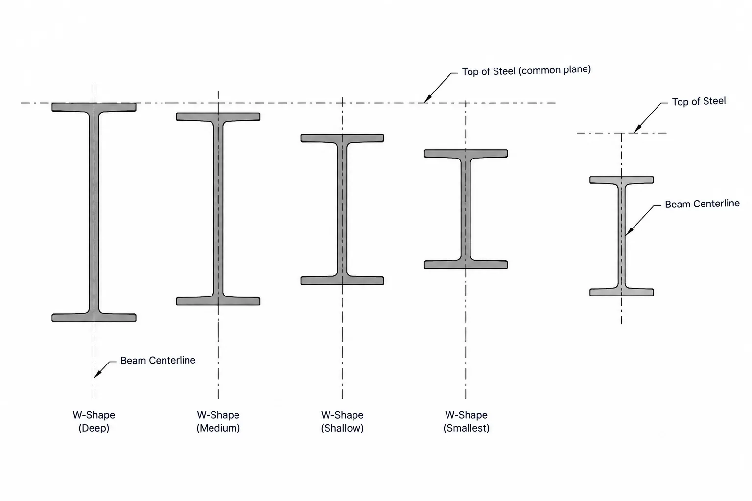
The datum is useful because many supported elements respond to the flange surface rather than the beam centroid. If several beams must form a common support plane, their top flanges may need to align even when the beams have different actual depths.
Top-of-steel should not automatically be interpreted as:
- The elevation of the member work line.
- The geometric centroid of the cross-section.
- The top of deck, slab, grout, or fireproofing.
- The highest point of a connection plate or projecting bolt.
- The theoretical high point of a cambered member.
Those may be separate elevations and should be labeled accordingly.
What Is a Beam Centerline Elevation?
A beam centerline elevation usually refers to the vertical location of the member reference line. In a simple prismatic model, that line may pass through the cross-section centroid or through a selected cardinal point. However, software settings and company modeling practices differ. A line displayed through the middle of a beam is not proof that it represents the centroid.
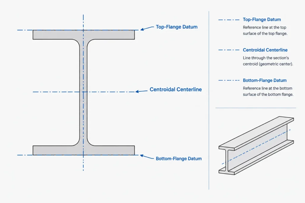
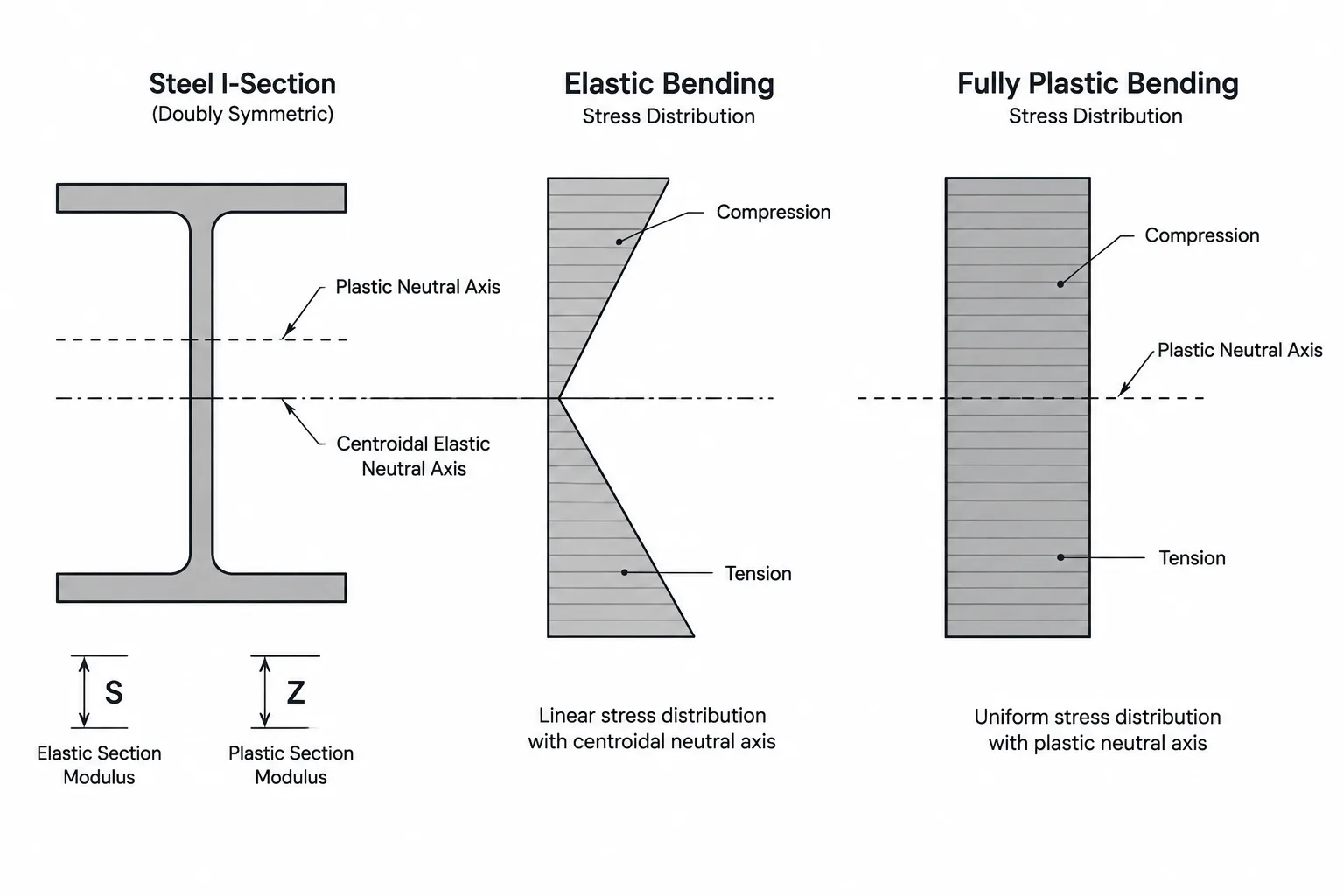
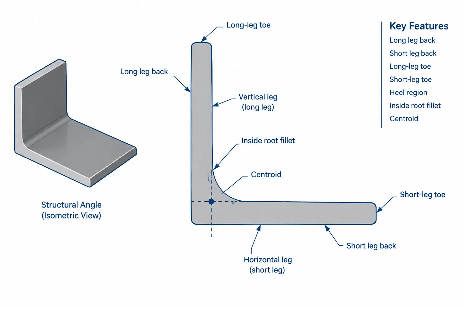
For a doubly symmetric rolled W-shape in its usual orientation, the centroid lies at mid-depth. In that limited case, a level beam centerline can be related to the flange surfaces using half the actual section depth. This convenient relationship should not be generalized to channels, angles, tees, unsymmetric built-up members, or members modeled with offsets.
How the Two Datums Relate
For a level, doubly symmetric I-shaped member with no vertical model offset, the conceptual relationship is straightforward:
Top-of-steel elevation = centerline elevation + one-half of the actual section depth.
Conversely:
Centerline elevation = top-of-steel elevation − one-half of the actual section depth.
The depth used in this relationship must come from verified shape data for the selected member. A nominal series label is not a substitute for actual published depth. Rolled shapes grouped under the same nominal depth can have different real depths, so exchanging one shape for another can move either the centerline or the top flange depending on which datum remains fixed.
Why section changes require an elevation decision
Suppose a beam size changes during design. There are at least two common outcomes:
- Top-of-steel remains fixed: The support plane is preserved, and the beam centerline and bottom flange may move.
- Centerline remains fixed: The analytical or geometric work line is preserved, and both flange elevations may change.
Neither approach is universally correct. The controlling datum depends on the framing system, connection concept, architectural interfaces, and project documentation. The revision should state what remains fixed rather than leaving the fabricator to infer it.
Common Datum Choices and Their Uses
| Datum | Typical use | Coordination concern |
|---|---|---|
| Top flange surface | Deck support, bearing planes, framing elevations | Actual section depth controls the centerline and bottom elevation |
| Member centerline or work line | Analysis models, framing geometry, sloped member layout | May not coincide with the physical section centroid |
| Bottom flange surface | Headroom, ceiling zones, equipment clearance | Top elevation changes when beam depth changes |
| Supporting seat or bearing surface | Joist seats, beam seats, shelf angles, bearing details | May be offset from the supporting member’s top flange |
| Connection work point | Skewed, sloped, or intersecting framing | Does not necessarily lie on a steel surface |
Top-of-Steel Coordination at Beam Intersections
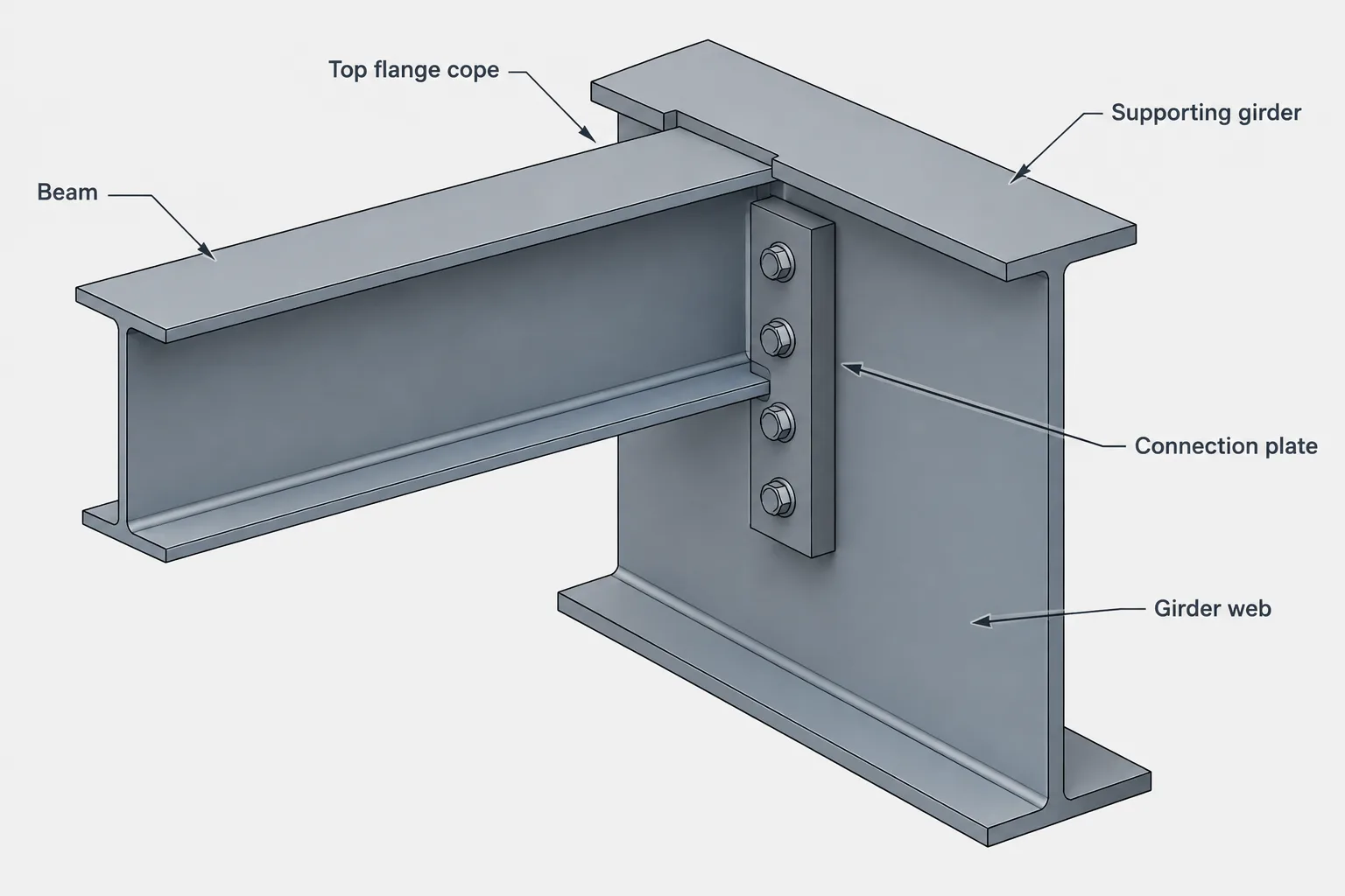
When beams frame into girders, a shared top-of-steel elevation can simplify deck support, but it does not make the members geometrically identical. Different depths place their centerlines and lower flanges at different elevations. Connection plates, bolt groups, copes, and stiffeners must be developed from the actual member geometry.
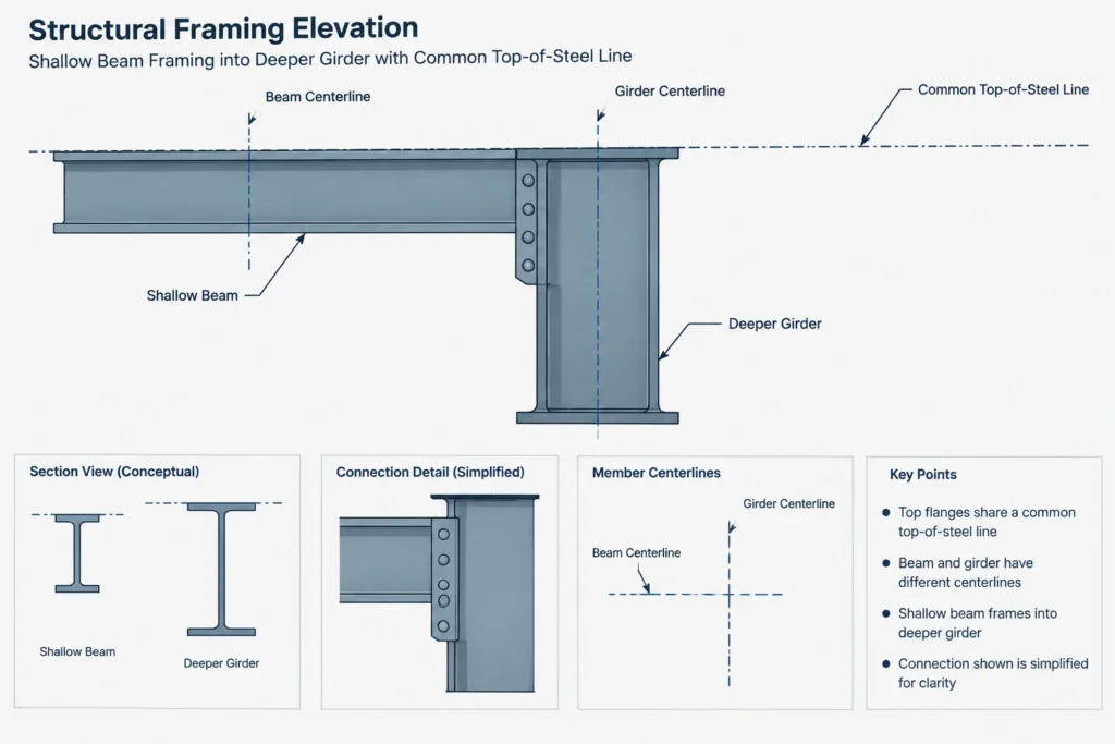
A beam framing into the side of a deeper girder may require its top flange to align with the girder top flange. The incoming beam centerline will then be determined by its own depth. If the connection is laid out from the girder centerline without accounting for that offset, the bolt pattern or plate position can be vertically misplaced.
Useful checks include:
- Confirm which member surface establishes the support plane.
- Verify actual depths from the controlling shape source.
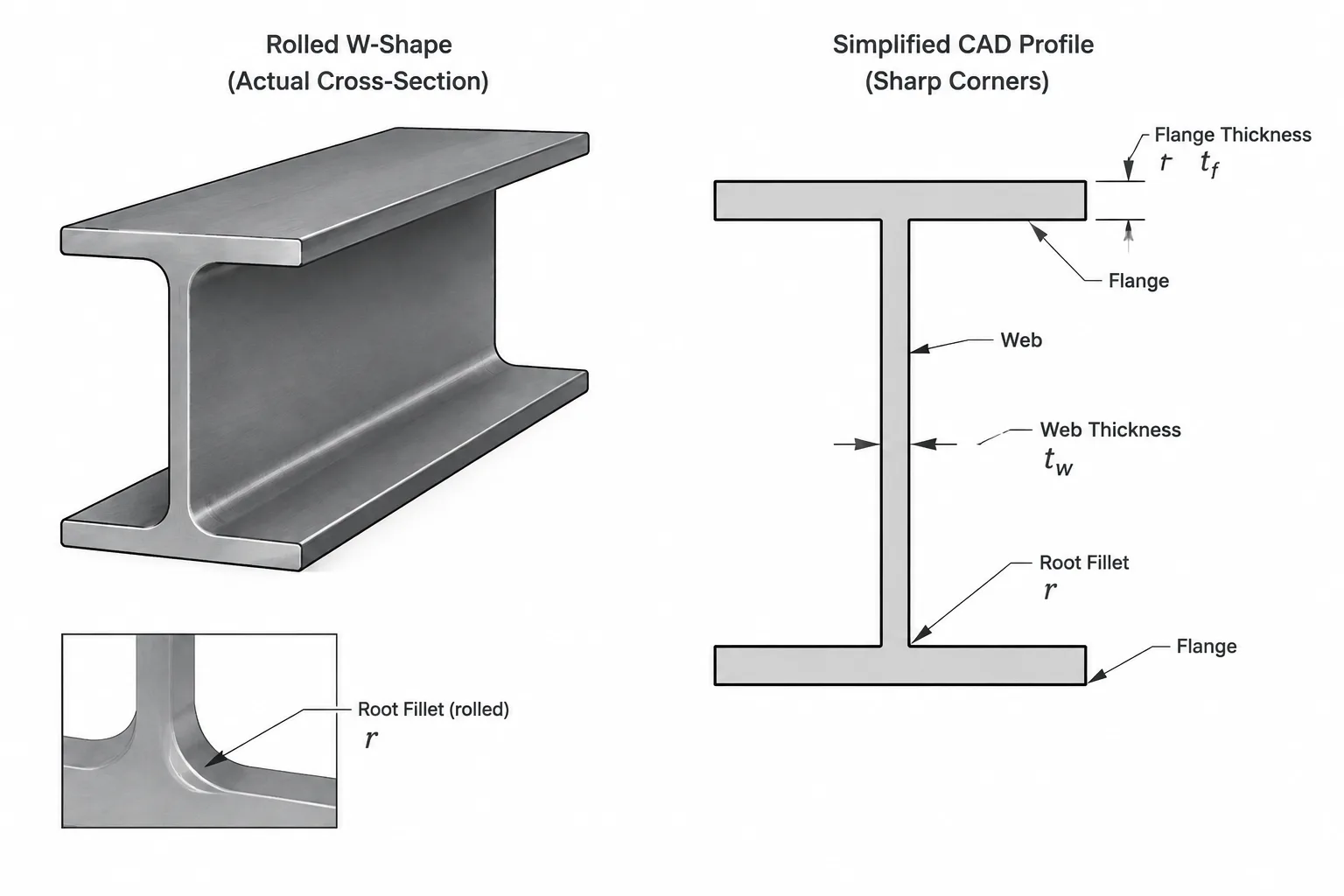
- Check beam-end copes against flange thicknesses and fillet zones.
- Locate connection holes from explicit datums rather than screen-picked edges.
- Review bottom-flange steps for clearance and architectural exposure.
- Coordinate any elevation difference at deck edges, openings, and transitions.
Sloped Beams Need a More Precise Definition
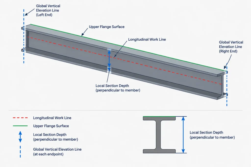
For a sloped beam, “top of steel” can refer to a line along the upper flange, but the reported elevation depends on where that line is evaluated. The elevation at one work point will differ from the elevation at another. A single elevation note is therefore insufficient unless it is tied to a specific endpoint, grid intersection, or station.
Section depth is normally measured perpendicular to the member’s longitudinal axis, while project elevations are vertical. On a sloped member, the vertical distance from its work line to a flange surface is not necessarily equal to half the section depth. A CAD or BIM model should use the member rotation and true section orientation when converting between local section offsets and global elevations.
Detailers should also distinguish between:
- The sloped work line connecting member work points.
- The physical plane or surface of the top flange.
- A vertical elevation measured at a named grid line.
- A perpendicular offset measured in the member’s local coordinate system.
Camber and Top-of-Steel Notes
Camber adds another distinction between theoretical layout geometry and fabricated shape. A beam may be located from nominal end work points while its flange rises between the ends. As a result, a top-of-steel elevation shown at an end does not by itself define the flange elevation everywhere along the span.
Camber should be communicated separately from framing elevations. Drafters should avoid reshaping the member work line merely to make a schematic model look cambered unless the modeling and downstream fabrication workflow specifically requires that representation. The relationship among nominal geometry, specified camber, deck support, and expected loading condition should remain visible in the project documentation.
CAD and BIM Workflow for Reliable Elevations
1. Establish the controlling project datum
Identify whether framing elevations are controlled by top of flange, centerline, bottom of steel, or another support surface. Record the convention in drawing notes and model documentation.
2. Check the member insertion point
Inspect the section’s cardinal point, justification, local axes, and vertical offsets. Do not assume the placement line passes through the centroid or top flange.
3. Use verified section geometry
Obtain actual depth and other required dimensions from a reliable shape reference. Avoid deriving geometry from nominal naming or from a simplified symbol that may not match the database section.
4. Separate physical and reference geometry
Keep work lines, grid lines, and elevation datums on recognizable layers or object classes. A physical flange edge should not be confused with a construction line used only for layout.
5. Test a shape substitution
Temporarily replace a member with another depth and observe what moves. If the top flange shifts when the design intent requires a fixed support plane, the object justification or offset strategy needs correction.
6. Review downstream outputs
Check sections, elevations, connection details, material lists, and exported fabrication geometry. A model can look correct in plan while carrying an incorrect vertical reference into shop drawings.
Drawing Practices That Reduce Ambiguity
Clear drawings connect each elevation to a named physical or geometric reference. Helpful practices include:
- Define abbreviations in the drawing legend.
- Attach elevation symbols to specific grid intersections or member ends.
- Label offsets when a beam work line does not coincide with its centroid.
- Show section cuts where members of different depths align at the top.
- Identify steps in top steel rather than implying a continuous plane.
- State whether revised member sizes hold top, centerline, or bottom elevation.
- Coordinate sloped members using endpoint elevations and work-point geometry.
The central rule is simple: an elevation must identify both a value and a reference. Top-of-steel and beam centerline elevations are related, but they are not interchangeable. Preserving the intended datum through design changes, modeling, connection detailing, and fabrication drawings prevents avoidable steps, clashes, and support-plane errors.