The W24x55 is a W-shape steel beam reference for engineers, detailers, fabricators, and students working with structural steel documentation. This page preserves the listed AISC-based dimensions and properties while adding practical context for reading the section data and using the accompanying CAD resource.
Use the source values below as the controlling local reference for this profile. For design work, confirm the applicable project requirements, material specification, connection assumptions, and engineering checks before selecting or detailing a member.
W Beam
refer to : AISC 16
the American Institute of Steel Construction (AISC) Specification for Structural Steel Buildings (AISC 360-16), which is the 2016 edition of the AISC Specification for Structural Steel Buildings. It provides guidelines and requirements for the design, fabrication, and erection of steel structures in the United States.
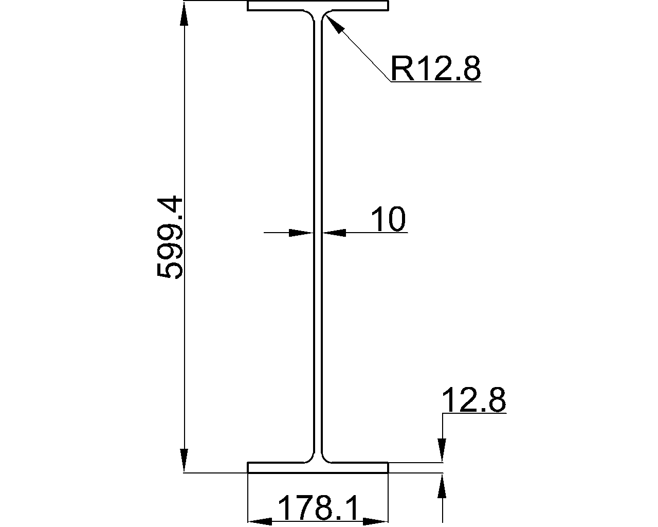
Depth : 599.4 mm
Width : 178.1 mm
Web Thickness : 10 mm
Flange Thickness : 12.8 mm
Root Fillet Radius : 12.8 mm
Sectional Area : 104.52 cm2
Unit Weight : 82 kg/m
How to read the W24x55 reference
The source identifies this member as a W Beam and reports its overall depth, flange width, web thickness, flange thickness, root fillet radius, sectional area, and unit weight. These properties describe the rolled cross-section and support different stages of engineering communication, from preliminary member identification to drafting and quantity review.
- Depth and width: These describe the principal envelope of the cross-section and help detailers coordinate the member with framing, clearances, and connected components.
- Web and flange thickness: These distinguish the thinner central web from the flanges and are important when reviewing detailing, weld locations, holes, copes, and local connection geometry.
- Root fillet radius: This is the curved transition between the web and flange. It matters when checking fit-up, bearing details, coping, and geometry near the flange-to-web junction.
- Sectional area and unit weight: These are useful for material takeoffs, weight estimates, and reference calculations. They should not be treated as a complete design check by themselves.
Using the CAD reference
The linked DWG resource can support drafting and coordination workflows. Before inserting it into a project drawing, check the file units, layer standards, origin, orientation, and whether the profile representation matches the project’s detailing convention. CAD geometry is a reference aid; it does not replace design calculations or project-specific connection detailing.
Related steel-reference topics
For broader context, pair this page with the site’s W-shape terminology guide, section-properties reference, structural steel connection guidance, and CAD/DWG resource instructions. Those related topics help explain how a listed shape is identified, reviewed, and incorporated into drawings without replacing the authoritative local data.
Frequently asked questions
What type of member is W24x55?
The source identifies W24x55 as a W Beam, a rolled structural steel shape with flanges and a connecting web.
Which reference is identified on this page?
The source refers to AISC 16 and identifies the American Institute of Steel Construction Specification for Structural Steel Buildings, AISC 360-16, as the referenced specification.
What properties are listed for W24x55?
The reference lists depth, width, web thickness, flange thickness, root fillet radius, sectional area, and unit weight. Review the source block for the authoritative values.
Can the DWG file be used directly for structural design?
The DWG is a drafting and coordination resource. It should be checked against project units and detailing requirements, and it does not replace engineering verification or connection design.
Does the listed unit weight complete a member design?
No. Unit weight supports estimating and material review, but member selection requires project-specific analysis, loading, limit-state checks, and detailing review by a qualified engineer.


