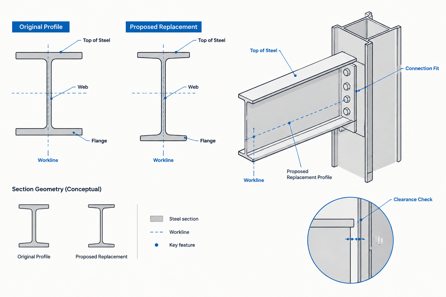
A structural steel member change can look simple on a schedule: replace one designation with another and update the callout. In practice, a different shape can affect section properties, connection geometry, elevations, clearances, weight, fabrication, and every drawing view where the member appears.
This is true even when the proposed replacement belongs to the same shape family or has a similar nominal depth. A heavier W-shape may have wider or thicker flanges. A new HSS may change its outside dimensions as well as its wall designation. Channels, angles, tees, and HP shapes introduce their own orientation and fit concerns.
The following steel shape substitution checklist is intended to support review and drawing coordination. It is not a method for approving a structural change. The engineer responsible for the design must verify structural adequacy, while the detailer and fabricator must confirm that the revised member can be connected, fabricated, handled, and erected as intended.
Start by identifying what kind of change is being proposed
Not every member revision has the same scope. Before editing a model or drawing, determine whether the change is:
- A different weight within the same nominal shape series
- A change to another nominal depth
- A switch between shape families, such as a W-shape to an HSS
- A change from a rolled shape to a built-up member
- A material-only change with the same section designation
- A temporary purchasing alternative that still requires formal review
The designation alone does not explain why the substitution was requested. Availability, connection fit, loading, vibration, fire protection, architectural clearance, shipping limits, or fabrication preferences may be involved. Record the reason and the approving party so the revision is not treated as an informal drafting adjustment.
Compare the complete section geometry
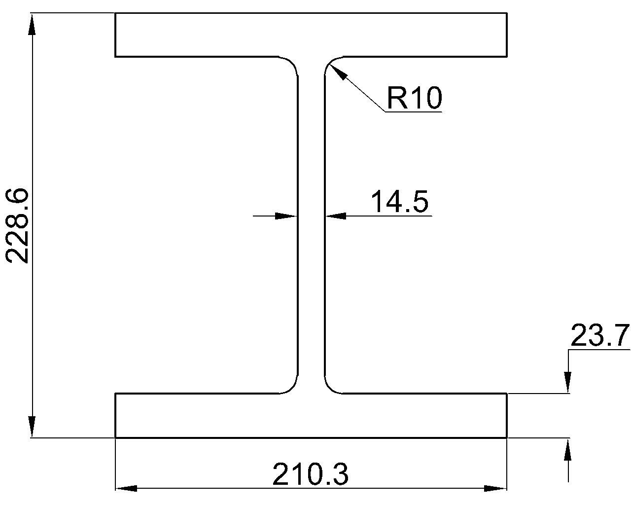
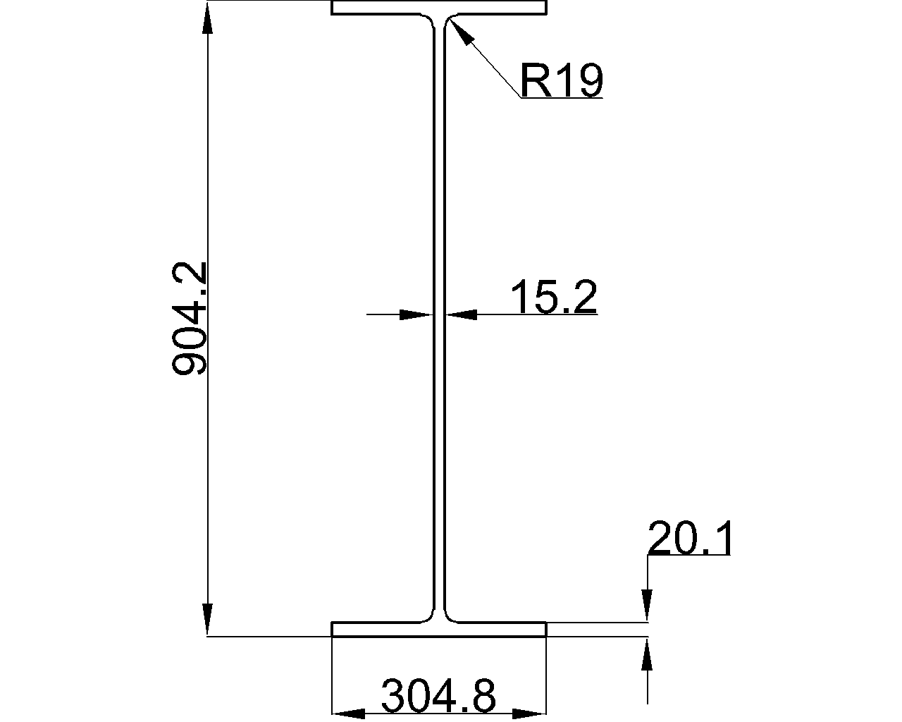
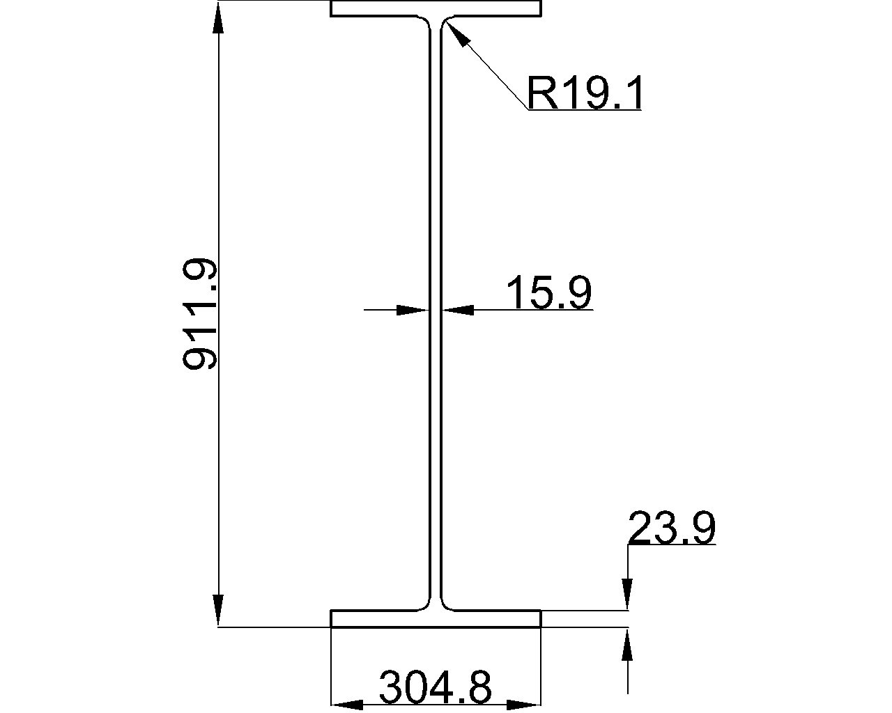
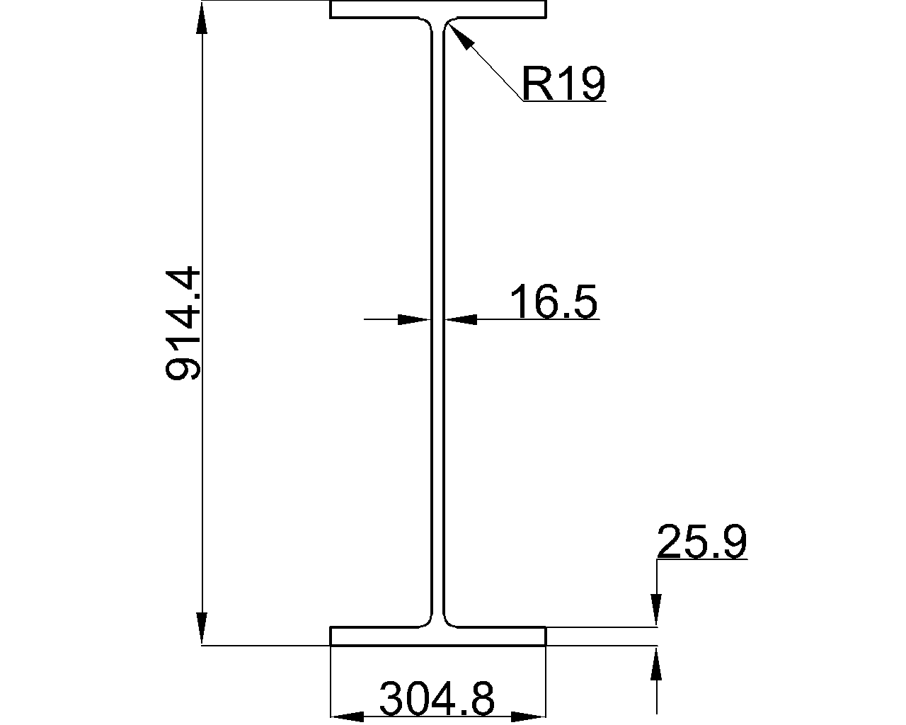
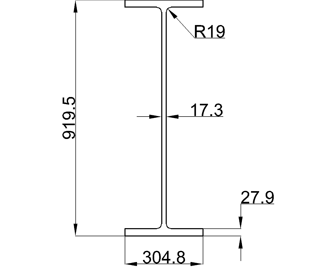
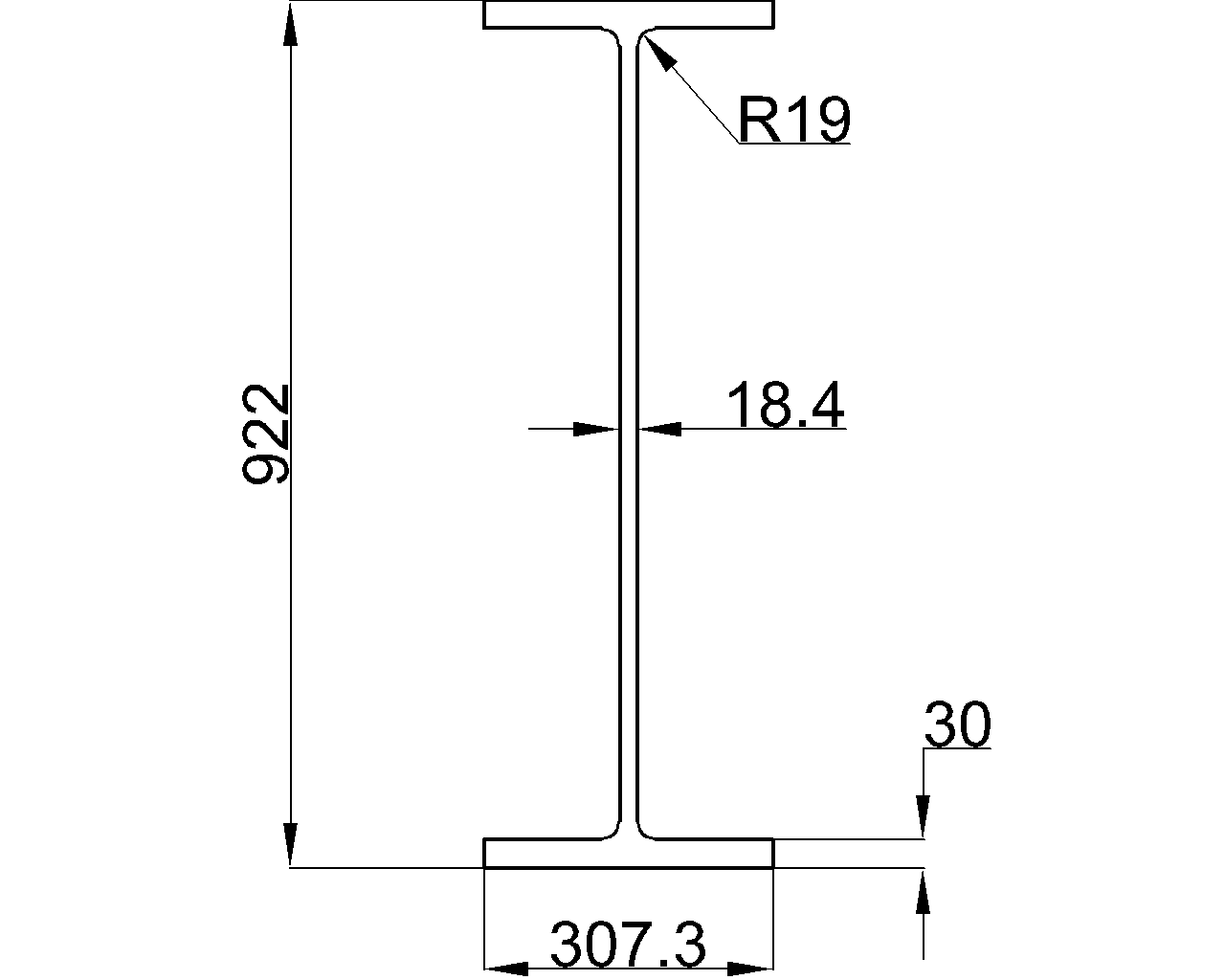
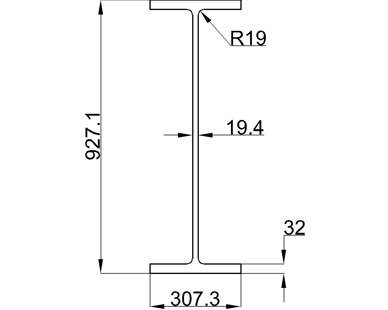
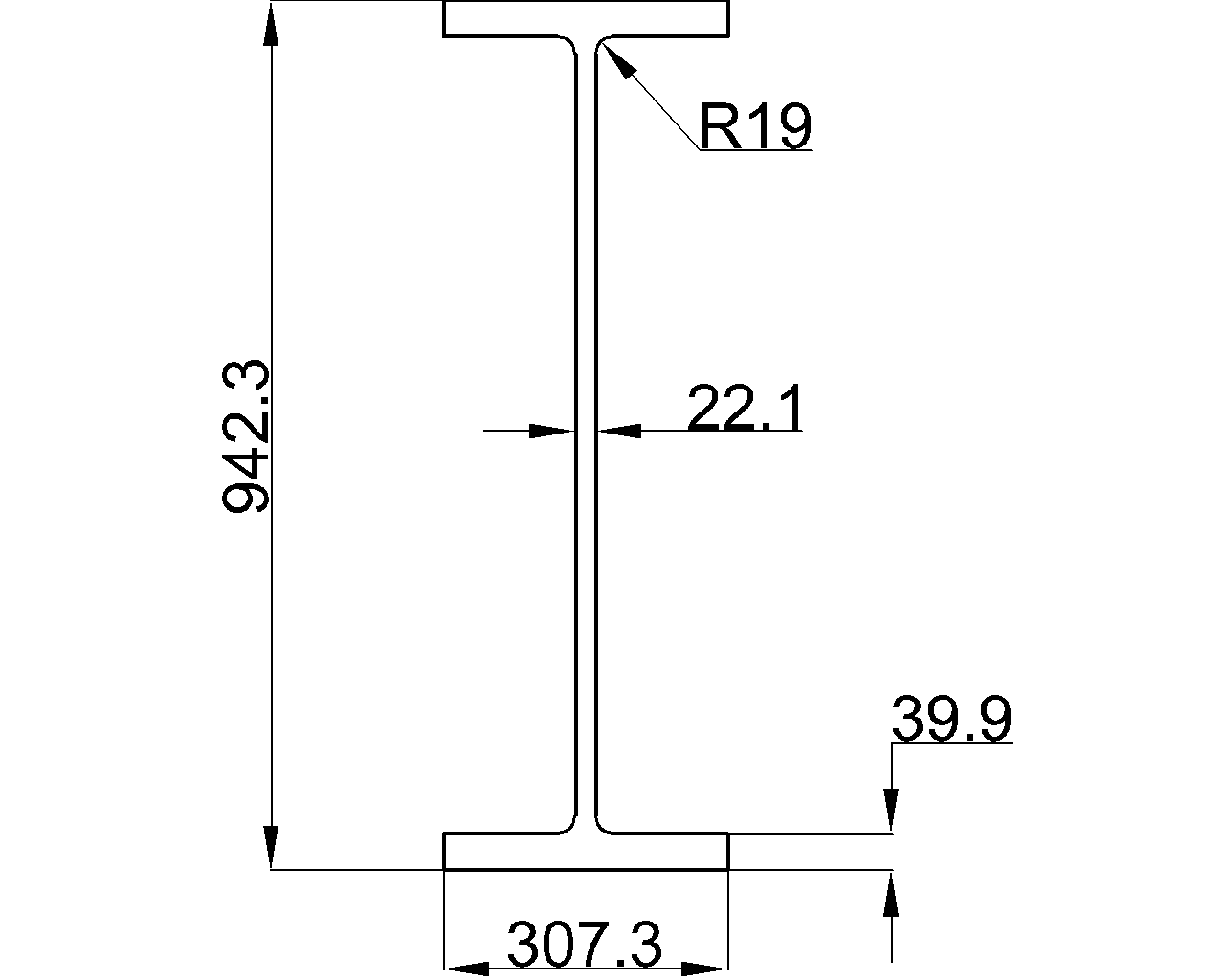
Nominal depth is only one part of member geometry. Shape tables should be used to compare the actual dimensions associated with both designations. Depending on the section family, the review may include:
- Overall depth and width
- Flange width and flange thickness
- Web thickness
- HSS outside dimensions and wall information
- Angle leg lengths and thickness
- Channel flange geometry and web depth
- Rolled fillets, corner radii, and detailing-clearance dimensions
- Cross-sectional area and weight per unit length
Two W-shapes with similar depths can still have noticeably different flange faces, web locations relative to connected material, or fillet encroachment. Likewise, two rectangular HSS sections that appear similar in an elevation may provide different face widths for plates, weld access, or adjacent finishes.
Use published shape data as the dimensional reference rather than scaling a drawing or assuming that a CAD block accurately represents every rolled feature. Simplified CAD geometry is useful for coordination, but it should remain traceable to verified section information.
Do not compare section properties one at a time
A proposed member should not be judged from weight, area, moment of inertia, or section modulus alone. Structural behavior may depend on several properties and on which axis is active. The relevant review is determined by the member function, bracing, loading, unbraced lengths, connection conditions, and applicable design criteria.
| Property or characteristic | Why a change may matter |
|---|---|
| Cross-sectional area | Influences member weight and may be relevant to axial-force checks. |
| Moment of inertia | Affects flexural stiffness and deflection behavior about the applicable axis. |
| Elastic or plastic section modulus | May be used in flexural strength evaluation, depending on the design method and limit state. |
| Radius of gyration | Relates to slenderness checks for compression members. |
| Torsional and warping properties | Can matter where twisting, eccentric loading, or lateral-torsional behavior is relevant. |
| Element width-to-thickness relationships | A change in flange, web, leg, or wall proportions can alter classification and limit-state behavior. |
A substitute can improve one property while reducing another. For example, a section with greater strong-axis stiffness is not automatically better about its weak axis or in torsion. Engineering review should therefore address the actual demands rather than relying on a single “larger” property.
Recheck the member reference line and controlling elevation
When a section depth or orientation changes, determine which geometric reference must remain fixed. Common controls include:
- Top of steel
- Bottom of steel
- Member centerline
- Column or grid centerline
- Outside face of an HSS or channel
- Back of an angle
- A work point at the intersection of framing lines
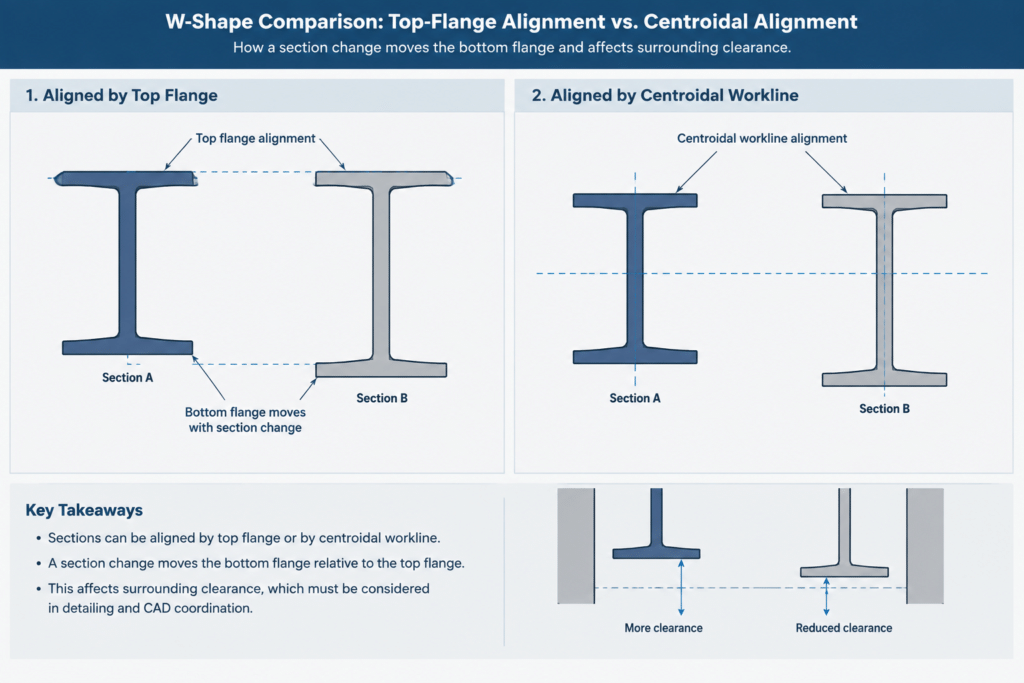
If top of steel remains fixed while beam depth changes, the bottom flange elevation moves. If the member centerline remains fixed, both top and bottom surfaces move. That distinction can affect ceilings, mechanical systems, deck support, cladding, fireproofing, access openings, and framing below.
Do not let the CAD software decide this implicitly. Establish the controlling face or workline before replacing the section profile, then inspect the revised geometry in plan, elevation, section, and three-dimensional views.
Review every connection affected by the new shape
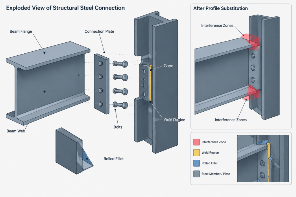
Connections are often where a seemingly reasonable substitution stops working. The new member may have adequate structural properties but insufficient physical room for the existing detail.
Bolted details
Recheck bolt gages, row spacing, edge and end conditions, hole locations, wrench access, and interference with flanges, webs, fillets, HSS corners, or adjacent fasteners. A thicker flange or web also changes the grip through connected plies and may affect the specified bolt assembly.
Welded details
Confirm that the connected elements still meet as drawn and that the revised geometry provides practical access for welding and inspection. Changes in wall, flange, or web thickness may require engineering review of the weld design rather than simply retaining the previous weld symbol.
Connection plates and supporting members
Check shear plates, clip angles, tees, end plates, flange plates, stiffeners, base plates, cap plates, and seats. Verify plate lengths and widths, cope geometry, clearances to rolled fillets, and whether the supporting member must also be revised. For HSS connections, review face width, corner regions, through-plates, diaphragms, and access to the interior where relevant.
Check adjacent construction and member intersections
A steel member rarely exists in isolation. Review the revised envelope against:
- Deck, joists, slabs, and edge angles
- Columns, beams, braces, and trusses
- Wall systems, façade supports, and architectural finishes
- Mechanical, electrical, plumbing, and fire-protection routing
- Stairs, rails, ladders, platforms, and equipment
- Required openings, sleeves, penetrations, and access zones
- Shipping splits, lifting points, and erection clearances
Pay particular attention to skewed framing and sloped members. A wider flange or deeper section can create interference that is not obvious in a conventional orthogonal view.
Update weight and fabrication information
A member substitution changes more than its section label. Recalculate member weight using verified weight-per-length data and the project’s established treatment of member length, plates, bolts, weld metal, and other attachments. The change may affect piece weights, assembly weights, shipping arrangements, lifting plans, or cost estimates.
Fabrication documents should also be checked for revised saw lengths, cope limits, hole coordinates, plate positions, weld preparation, templates, CNC data, and bills of material. If the member has already been released or fabricated, the revision process must clearly identify its status. Editing a model does not by itself communicate a shop or field change.
Use a controlled CAD and drawing revision workflow
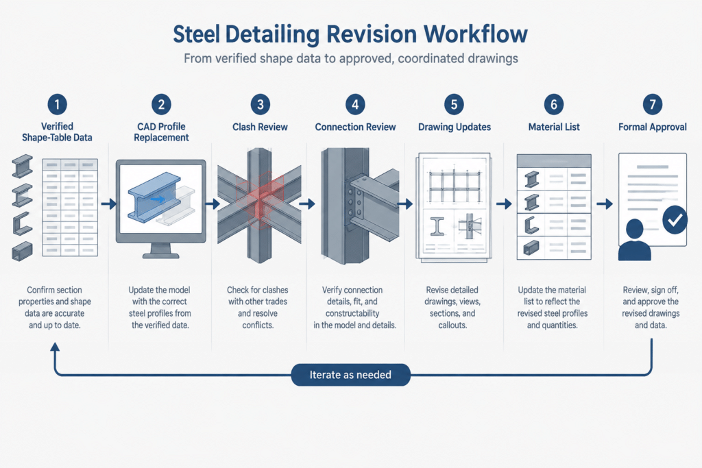
A reliable workflow keeps the old and new conditions distinguishable until approval and coordination are complete:
-
Record the requested substitution and its source.
-
Obtain verified dimensional and section-property data for both shapes.
-
Copy or revision-track the affected model and drawing information rather than overwriting the original condition without a record.
-
Replace the section while preserving the correct workline, orientation, and controlling elevation.
-
Run interference checks and inspect connections in multiple views.
-
Update member marks, schedules, section labels, details, material lists, and calculated weights.
-
Route structural and fabrication impacts to the responsible reviewers.
-
Issue the accepted change through the project’s formal revision process.
Search the drawing set for the previous designation before issue. The old callout may remain in sections, details, schedules, notes, erection plans, or exported files even after the model object has been changed.
Common substitution mistakes
- Matching nominal depth only: Actual depth, width, thickness, and properties can still differ.
- Matching weight only: Similar weight does not establish equivalent strength, stiffness, stability, or geometry.
- Ignoring orientation: Channels, angles, tees, and rectangular HSS can behave and fit differently when rotated or mirrored.
- Keeping connection details unchanged: Existing holes, plates, welds, and copes may no longer align or remain appropriate.
- Moving the wrong reference face: An uncontrolled profile swap can alter top of steel or other critical elevations.
- Updating only one drawing: Member information commonly appears in several views, schedules, models, and fabrication outputs.
- Treating availability as approval: A shape being obtainable does not make it an acceptable structural substitute.
A substitution is a coordinated design revision
The safest way to handle a steel shape change is to treat it as a coordinated revision rather than a text replacement. Compare verified geometry and section properties, preserve the intended workline, recheck every affected connection, review adjacent construction, and update downstream fabrication information.
Shape database pages and CAD profiles can make that work faster by supplying organized reference information. They do not replace engineering judgment, project requirements, or formal approval. The final member must satisfy both the structural intent and the physical realities of detailing, fabrication, and erection.