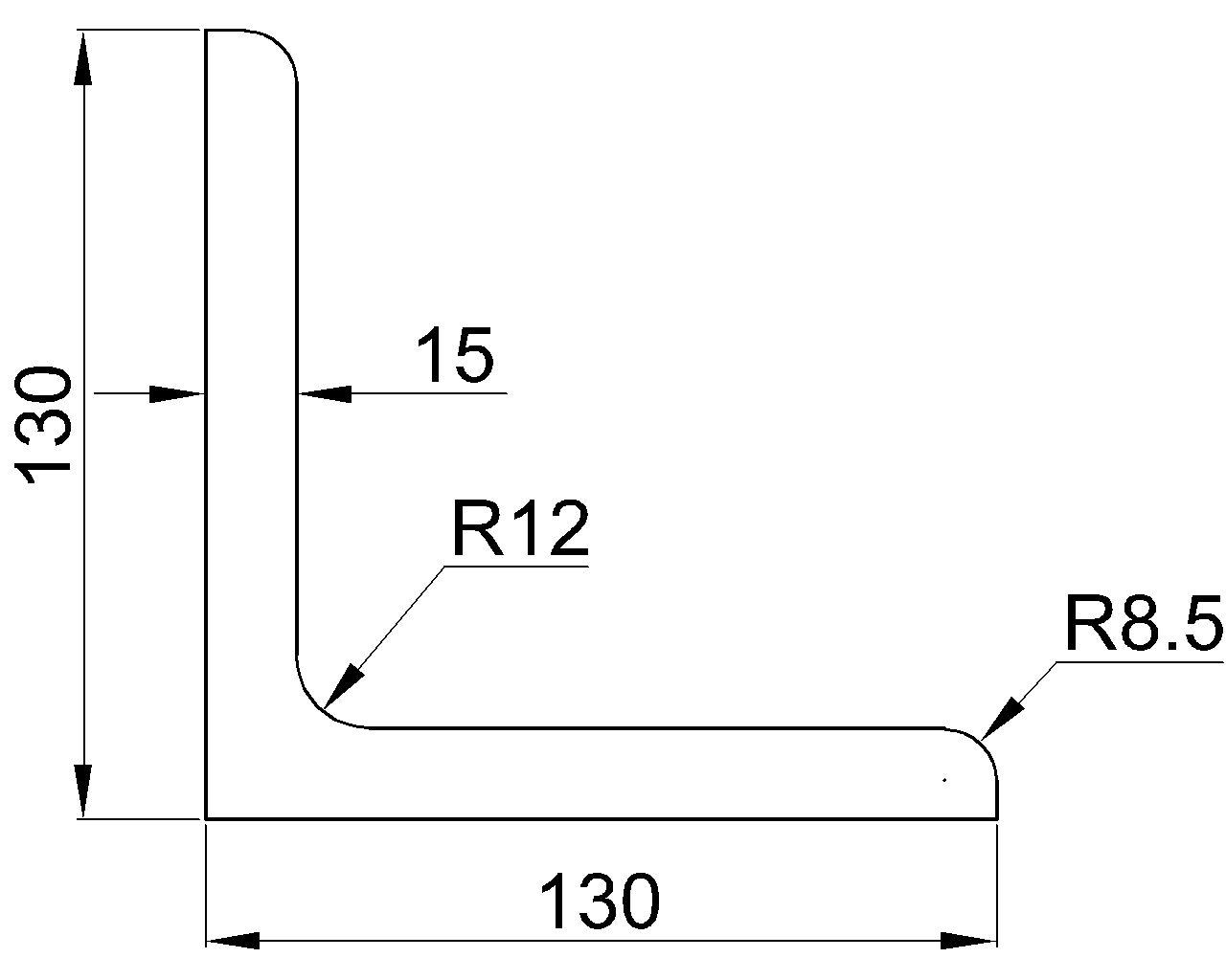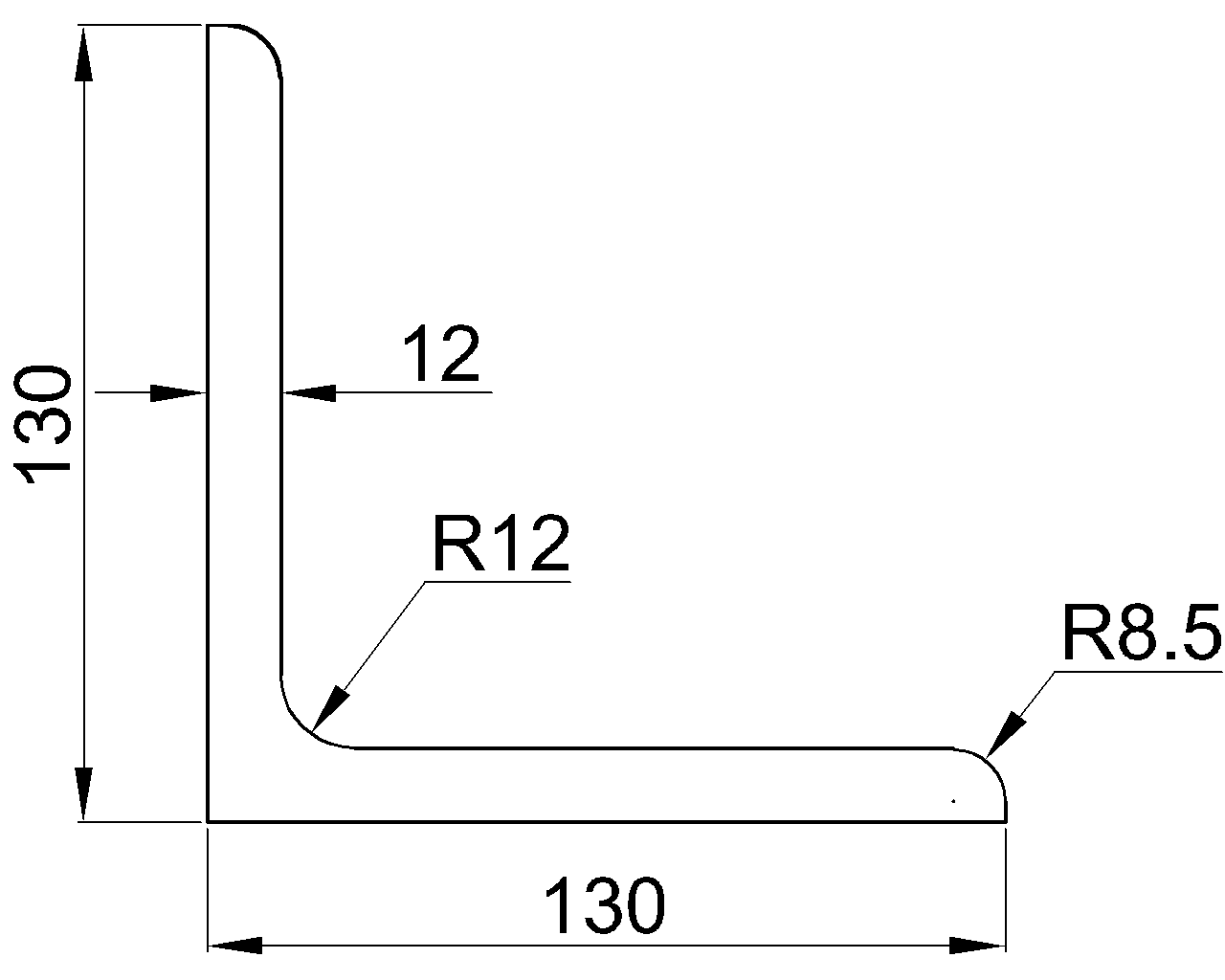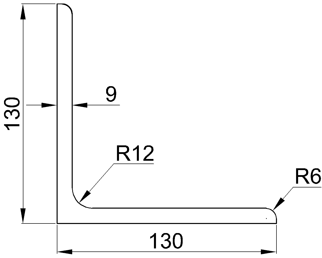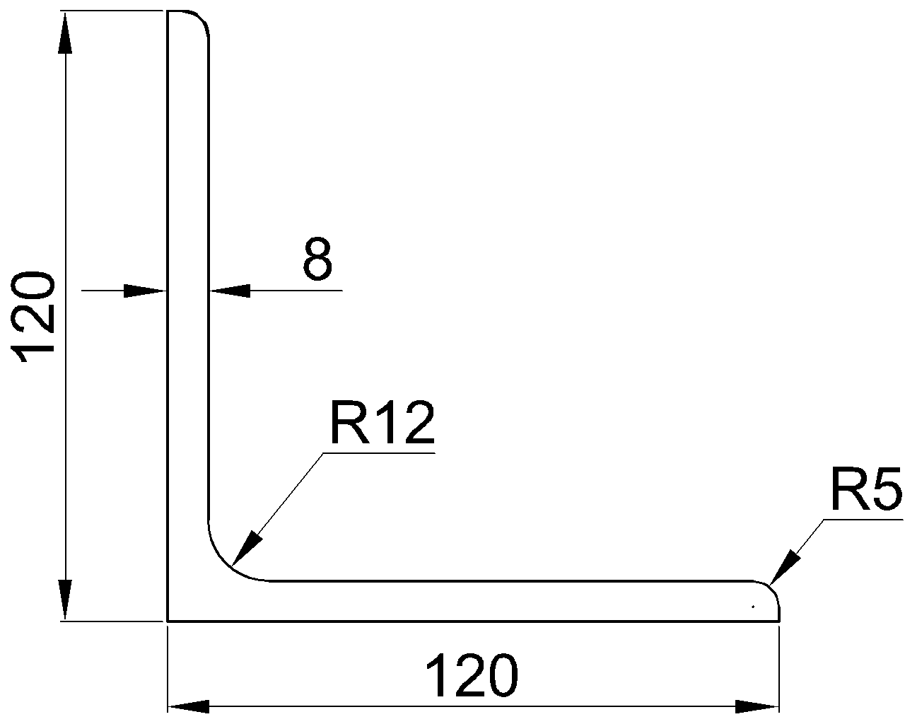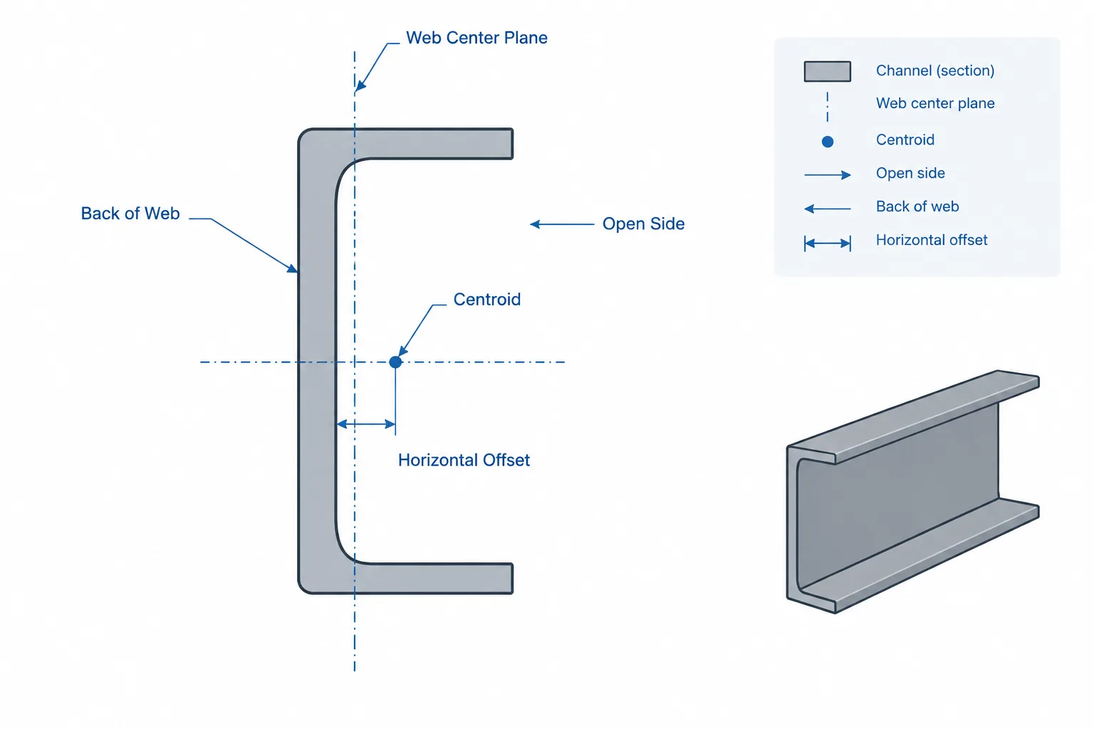
A structural channel is symmetric about its mid-depth axis, but it is not symmetric across its web. Because both flanges project toward the open side, the section centroid is displaced from the back of the web. This steel channel centroid offset matters whenever a drafter, designer, or fabricator uses a web face, member centerline, bolt line, or work line as the controlling reference.
The distinction can be easy to miss in plan views and simplified linework. A channel may be drawn as a single line, inserted from a convenient web-back point, or modeled along an analytical member axis. Those references are not automatically interchangeable. Understanding where the centroid lies helps prevent incorrect offsets, unexpected eccentricity, and alignment problems in built-up assemblies.
Why the centroid is not at the web centerline
The centroid of a cross section is the area-weighted average location of its component parts. In a channel, the web contributes area near the web plane, while the two flanges extend toward the open side. Those projecting flanges pull the centroid away from the web back and toward the flange toes.
The centroid still lies on the horizontal symmetry axis at mid-depth because the top and bottom halves of a typical channel section mirror each other. Across the width, however, there is no corresponding symmetry. The horizontal centroid coordinate must therefore be obtained from verified section data or calculated from the actual geometry.
The centroid may fall in an open portion of the cross-section rather than within the steel itself. That is not an error. A centroid is a geometric property of the entire area distribution and does not need to lie inside the material.
Common channel reference lines
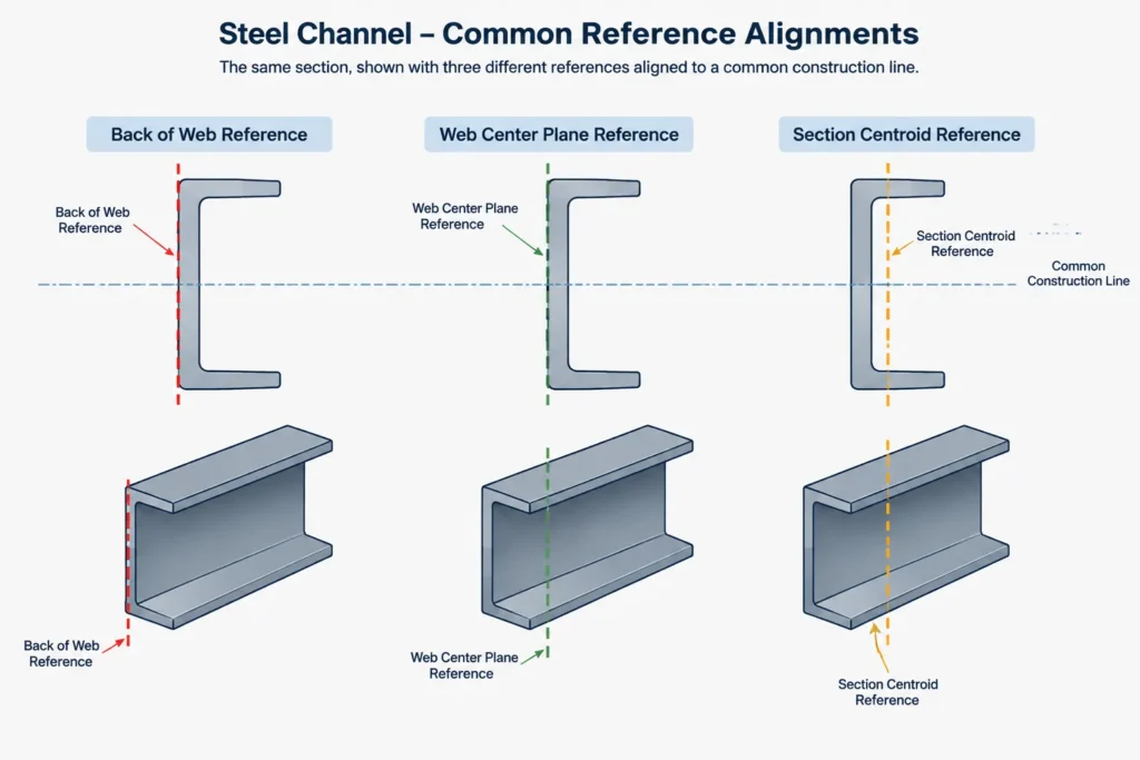
Several legitimate reference lines may appear in channel drawings and models. Problems arise when one is assumed to represent another without an explicit offset.
| Reference | What it represents | Typical use |
|---|---|---|
| Back of web | The outside surface at the closed side of the channel | Face-of-steel layout, attachment locations, and clearance coordination |
| Web center plane | A plane based on the web thickness | Plate alignment, conceptual modeling, and some connection layouts |
| Section centroid | The area-weighted center of the complete channel | Analysis axes, section properties, and centroidal member placement |
| Member work line | A project-defined line used to establish framing geometry | Grid intersections, framing plans, slopes, and member end locations |
| Bolt or connection line | The centerline of fasteners or another load-transfer feature | Connection detailing and eccentricity evaluation |
A project may intentionally place the work line at the web back, web center, centroid, or another location. The important requirement is to identify the convention and carry it consistently through plans, details, models, and fabrication information.
Reading the offset from shape data
Channel shape tables commonly provide a horizontal centroid coordinate measured from a stated reference, often the back of the web. The exact symbol and reference convention depend on the source. Before using the value, confirm all of the following:
- The listed shape designation matches the specified channel.
- The table defines the point from which the coordinate is measured.
- The value is expressed in the units used by the drawing or model.
- The channel orientation in CAD matches the table diagram.
- The data describes the rolled shape rather than an idealized sharp-corner outline.
Do not assume that half the overall flange width locates the centroid. A channel is not a rectangle, and its web, flanges, fillets, and possible flange geometry all contribute to the published centroid location. A simplified CAD outline may also produce a slightly different result from authoritative tabulated properties.
Using a signed offset in CAD
A reliable CAD workflow starts by choosing a local coordinate system. For example, the local vertical axis can follow the channel depth, while the local horizontal axis points from the web back toward the open side. With that convention, the centroid coordinate can be expressed conceptually as:
centroid position = reference position + signed centroid offset
The sign is important. Mirroring or rotating a channel changes the global direction of the offset even though the section property itself is unchanged. A channel opening to the right and the same channel opening to the left require opposite global offsets from a common web-back reference.
Recommended modeling sequence
- Establish the project work line and document what it represents.
- Insert or draw the channel using a known base point.
- Orient the web back and open side correctly.
- Apply the verified centroid offset if the analytical or member line must pass through the centroid.
- Keep face-of-steel and centroidal construction lines on distinguishable layers or object styles.
- Check mirrored members rather than assuming a copied offset remains valid.
- Confirm connection geometry from physical faces, not only from the analytical line.
If a reusable channel block is involved, its insertion point should be documented. Two geometrically accurate blocks can behave differently if one inserts at the centroid and the other at the back of the web.
Connection eccentricity and load lines
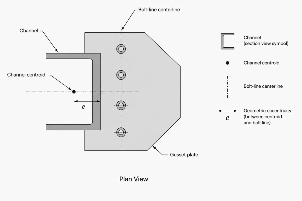
A connection attached through the channel web often transfers force along a line near the web. Because the channel centroid is offset toward the open side, that connection line may not pass through the centroid. The transverse difference can create eccentricity and associated moment or torsional effects.
For geometric checking, the relationship can be written as:
eccentricity = load-line coordinate − centroid coordinate
This expression identifies the geometric offset; it does not by itself establish connection strength or adequacy. The actual design depends on the load path, restraint, connection configuration, member behavior, and governing project criteria. Drafters should preserve the intended geometry and flag unclear load-line assumptions for engineering review.
Common situations requiring attention include a channel connected through its web to a gusset, a channel used as an edge member, a ledger channel supporting framing on one side, and a channel welded to a plate along the web back.
Back-to-back channels
Two identical channels arranged back-to-back can form a built-up member with symmetry that an individual channel does not have. If the channels have matching orientation, size, and spacing, the centroid of the combined section lies on the assembly symmetry plane. That plane may be between the web backs or within a defined separation gap.
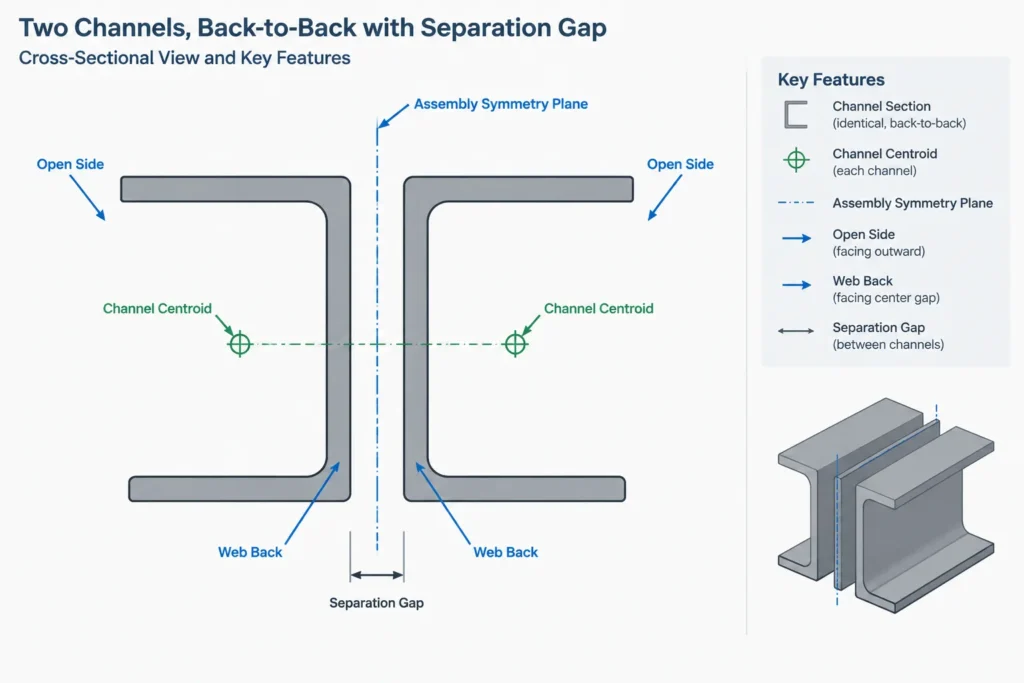
Do not place each component channel directly on the assembly centerline. Each individual channel centroid remains offset toward its own open side. Instead, establish the assembly center plane, locate both web backs from the specified spacing, and then verify the combined geometry.
Connection plates, separators, stitch elements, and other added material can alter the centroid of the complete built-up section. Their contribution should be included when properties are calculated for the actual assembly. Published properties for one rolled channel are not automatically the properties of a pair.
Centroid versus shear center
The centroid and shear center are different points. The centroid describes the distribution of cross-sectional area. The shear center is the point through which transverse loading can act without inducing twist under the idealized section behavior used in analysis.
For a channel, these points generally do not coincide. Placing a model line through the centroid therefore does not mean that transverse loading applied on that line is free of torsional effects. CAD geometry should preserve the specified member location, while structural analysis should use the appropriate section and load application assumptions.
Drawing checks before release
- Verify whether dimensions control the web back, web center, centroid, or work line.
- Show the channel opening direction clearly in plans and sections.
- Check that mirrored or opposite-hand members have the intended offset direction.
- Confirm that bolt lines and plates are located from physical steel faces.
- Review clearances using the actual channel envelope, including flange projections.
- Do not derive authoritative section properties from a simplified CAD block.
- Coordinate analytical centerlines with fabrication geometry when models are exchanged.
Practical takeaway
A channel’s web back, web center plane, centroid, connection line, and member work line can all occupy different locations. The channel centroid offset is therefore not merely a table value; it is a translation between analytical geometry and physical steel.
For dependable detailing, define the reference line first, obtain the centroid coordinate from verified shape data, apply the offset in the correct direction, and check connections from actual faces and hole locations. This workflow keeps channel orientation, built-up member layout, and model coordination clear without treating unlike reference lines as though they were the same.