Elastic section modulus is often presented as a single property for each bending axis. That works neatly for a doubly symmetric W-shape, but it can be misleading when the cross section is not symmetric about the axis of bending. Structural tees, channels, angles, and many built-up members may have unequal distances from the centroidal axis to their opposite extreme fibers. Because elastic section modulus depends on that distance, the two sides can have different values.
This distinction matters when reading shape tables, checking CAD-generated properties, or evaluating which edge reaches a limiting bending stress first. It also helps explain why rotating or mirroring a section can change which listed property applies to a particular physical face even though the steel shape itself has not changed.
Start with the elastic bending relationship
For elastic bending about a centroidal axis, normal stress varies linearly across the section. The familiar relationship can be written as:
f = M c / I = M / S
In this expression:
fis the calculated bending stress at the fiber being checked.Mis the bending moment about the applicable centroidal axis.Iis the second moment of area about that axis.cis the perpendicular distance from the axis to the fiber.Sis the elastic section modulus, calculated asI/c.
A section has one value of I about a selected centroidal axis, but it can have two different extreme-fiber distances. If c is different on the two sides, then I/c is also different.
Why symmetry produces a single familiar value
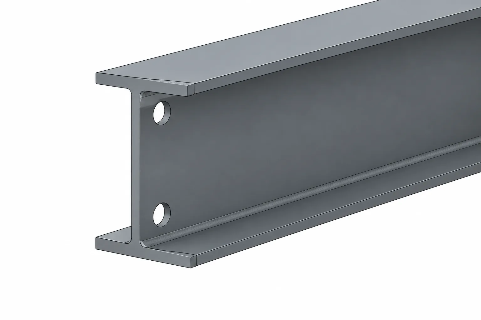
Consider a cross section that is symmetric about its horizontal centroidal axis. The centroid falls midway between the top and bottom extreme fibers, so the distances to those fibers are equal. Dividing the same moment of inertia by equal distances produces equal elastic section moduli for the two sides.
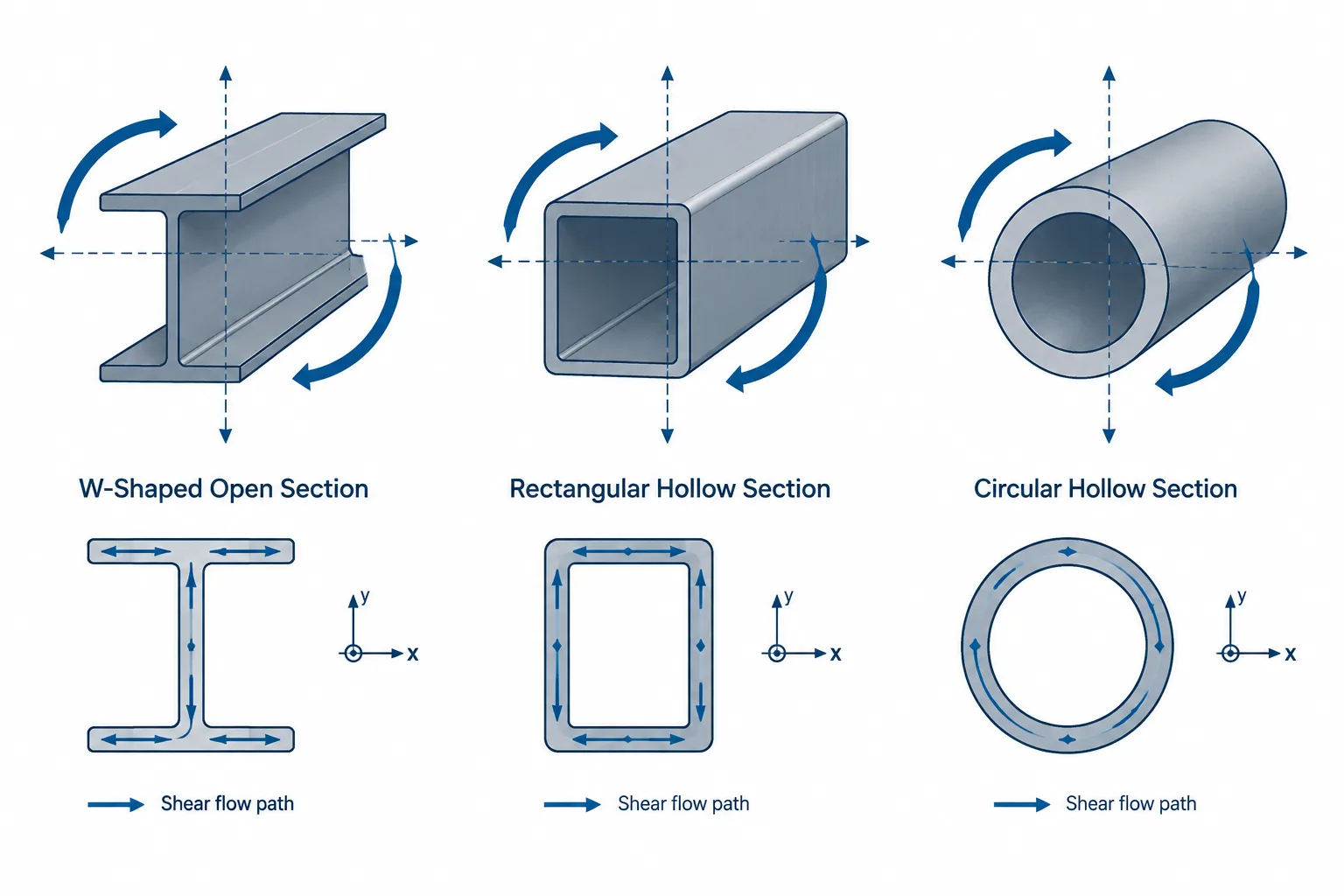
This is why bending about the major axis of a typical W-shape is commonly represented by one Sx value. The same logic applies about its minor axis when the section is symmetric from side to side.
Symmetry should be evaluated about the particular bending axis, not assigned to the shape in a general sense. A channel may be symmetric about its horizontal axis but unsymmetric about its vertical axis. A structural tee is typically symmetric about the vertical stem axis but not about its horizontal axis.
Two extreme fibers mean two possible section moduli
For an unsymmetric cross section, label the distances from the centroidal axis to the opposite extreme fibers as c1 and c2. The corresponding elastic section moduli are:
S1 = I/c1S2 = I/c2
The fiber farther from the centroid has the larger c distance and therefore the smaller elastic section modulus. For a given moment magnitude, that side develops the larger extreme-fiber stress.
This gives a useful geometric check:
- The side farthest from the centroid should have the smaller
S. - The side nearest the centroid should have the larger
S. - If the distances are equal, the two values should match.
The smaller value is not automatically the only property relevant to every problem. Moment direction determines which physical side is in tension and which is in compression. Design checks may also involve different limit states, bracing conditions, local elements, connections, or material behavior on the two sides.
How common steel shapes behave
| Shape type | Typical symmetry | Section-modulus implication |
|---|---|---|
| W-shape | Usually symmetric about both centroidal axes | Opposite extreme-fiber values normally match for bending about either principal centroidal axis. |
| Channel | Commonly symmetric about the axis parallel to the flanges, but not about the web-centered direction | One bending direction may use equal values, while the other can have different values at the web back and flange-toe side. |
| Structural tee | Symmetric about the stem centerline but not between flange and stem tip | Bending that places stress across the flange-to-stem depth can require separate flange-side and stem-side values. |
| Single angle | Generally unsymmetric about ordinary horizontal and vertical reference axes | Interpretation requires careful attention to centroidal axes, principal axes, leg orientation, and table conventions. |
| Built-up section | Depends on component arrangement | The centroid and both extreme-fiber distances should be established from the completed section geometry. |
Structural tees
A tee provides the clearest visual example. Its centroid is generally closer to the flange than to the tip of the stem. The distance from the centroid to the stem tip is therefore different from the distance to the outer flange face. The same centroidal moment of inertia produces two elastic section moduli, one for each extreme side.
Channels
For a channel, the centroid does not generally lie halfway between the back of the web and the tips of the flanges. Bending about the centroidal axis that distinguishes those sides can produce different extreme-fiber values. Channel orientation must therefore be coordinated with the property labels used in the reference table or analysis model.
Angles
Angles require additional care because their principal axes are rotated relative to leg-based reference directions. A property about a principal axis should not be substituted directly for a property about a horizontal or vertical modeling axis. When bending is not aligned with a principal axis, stress evaluation may require unsymmetric-bending relationships rather than a simple isolated use of one section modulus.
Positive and negative labels do not make S a signed property
Some references or software reports distinguish sides with labels such as positive and negative, top and bottom, left and right, or maximum and minimum. These labels identify the extreme fiber associated with the calculation. They do not necessarily mean that the geometric section modulus itself should be treated as a negative quantity.
The sign of bending stress comes from the adopted moment and coordinate conventions. A table may report section-modulus magnitudes while using subscripts to identify the applicable side. Before using a value, confirm:
- Where the coordinate origin is located.
- Which direction each local axis points.
- Whether the side label refers to coordinate sign or a physical feature.
- Whether the software reports a magnitude or a signed result.
A practical table-reading workflow
- Identify the bending axis. Determine whether the moment acts about the table’s x-axis, y-axis, or a principal axis.
- Confirm section orientation. Locate the flange, web, stem, heel, toes, and open side relative to the axis diagram.
- Find the centroid. Use the published centroid location or a verified geometric calculation.
- Determine both extreme-fiber distances. Measure perpendicular to the bending axis, not along a leg or sloped boundary.
- Match each S value to a physical side. Do not rely on top, bottom, positive, or negative labels until the axis convention is understood.
- Check the geometry logically. The farther extreme fiber should correspond to the smaller section modulus.
- Track moment direction separately. Establish which side is in tension or compression for the applicable load case.
Checking the values in CAD
A CAD region or section-analysis tool can provide a useful independent check, but only when the modeled outline represents the intended section. Simplified sharp-corner geometry may not reproduce published properties for rolled shapes that include fillets, tapered elements, or other production geometry.
For a controlled check, place the section in a known coordinate system and record the centroid and centroidal moment of inertia. Draw construction lines through the centroid, then measure perpendicular distances to both extreme fibers. Calculate I/c separately for each side.
If the CAD results do not match a published table, investigate the outline, axis assignment, units, and reference conventions before assuming the table is wrong. Mirroring a section should preserve its property magnitudes, but it may swap which physical side corresponds to a positive or negative axis label. Rotating it can also change how local properties map to global model axes.
Do not confuse elastic and plastic section modulus
The two-side issue described here concerns elastic section modulus and the centroidal neutral axis used in linear-elastic bending. Plastic section modulus is based on the plastic neutral axis and the distribution of areas on its opposite sides. It is not obtained by simply choosing one of the elastic values or averaging them.
Similarly, the smaller elastic section modulus identifies the side that reaches a given elastic stress first under a specified moment magnitude. It does not, by itself, establish a member’s complete design strength or suitability. Stability, local slenderness, yielding, connection behavior, load direction, and applicable design provisions still require evaluation.
Key drafting and calculation takeaway
Whenever a steel shape is unsymmetric about the bending axis, treat elastic section modulus as a side-specific property. Start with the same centroidal I, determine the distance to each opposite extreme fiber, and calculate or select the corresponding S value. Then map that side to the actual section orientation and moment direction shown in the model or drawing.
This approach prevents a common mistake: selecting a familiar section-modulus label without confirming which edge it represents. For channels, tees, angles, and built-up sections, a small axis sketch beside the calculation is often the simplest and most reliable control.