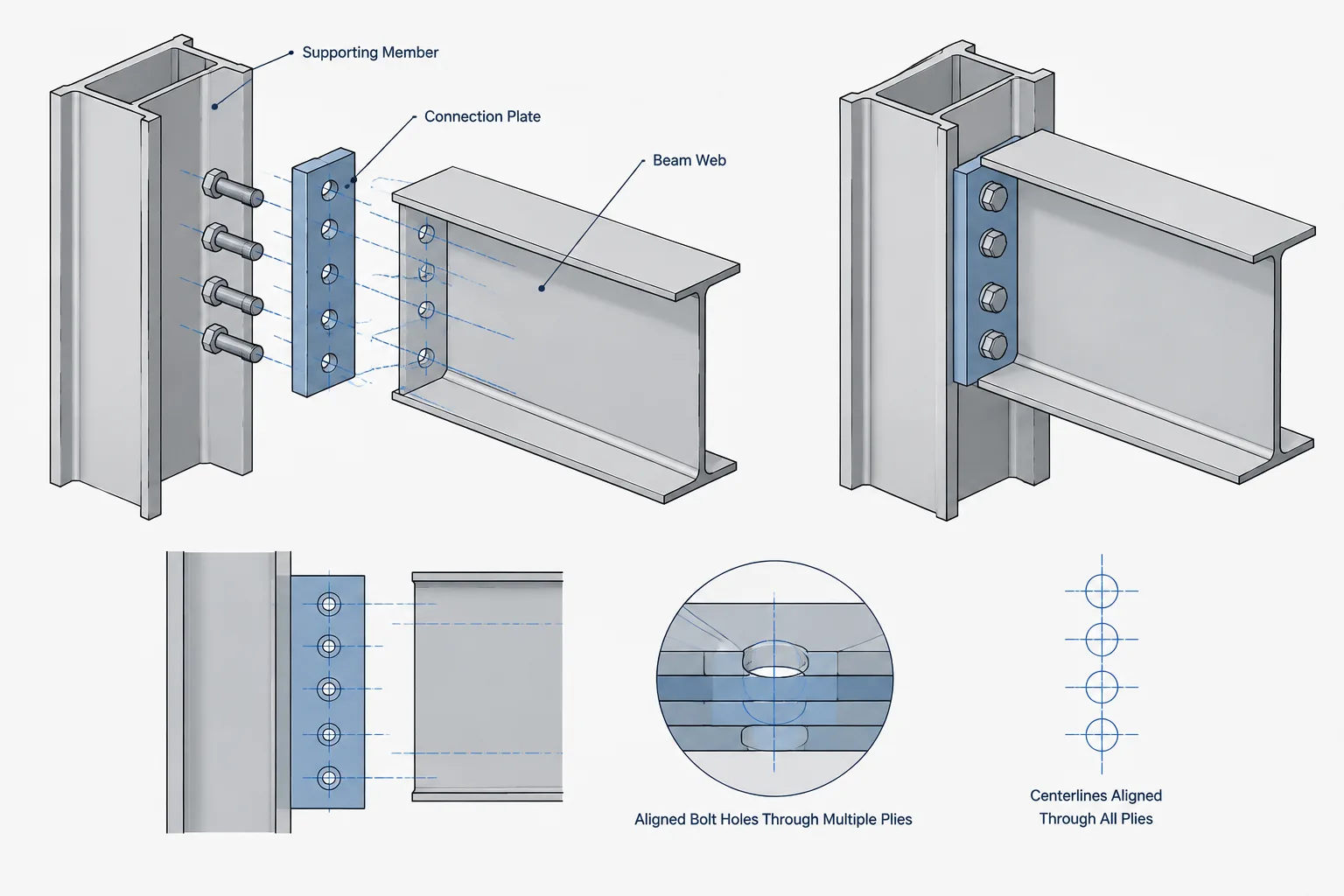
Steel beam seat connections support a beam from below rather than relying only on bolts or welds through the beam web. This makes the connection visually intuitive: the beam end bears on a horizontal seat, and the reaction passes from the bottom flange into the supporting member. The actual behavior and detailing, however, involve more than placing an angle beneath the beam.
The seat must have adequate strength and stiffness, the beam needs enough bearing area, and the assembly must be practical to fabricate and erect. Drafters must also coordinate beam length, end clearance, rolled-shape fillets, weld access, bolt installation, and any component used to restrain the top of the beam.
This article explains the geometry and coordination of seated connections. Connection capacity, weld sizing, bolt selection, local supporting-member checks, and beam limit states remain engineering tasks governed by the project design criteria and applicable standards.
What Is a Seated Beam Connection?
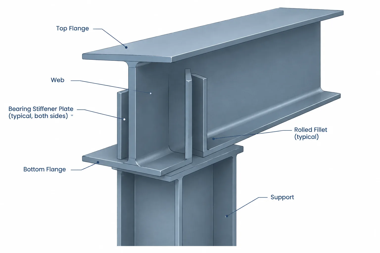
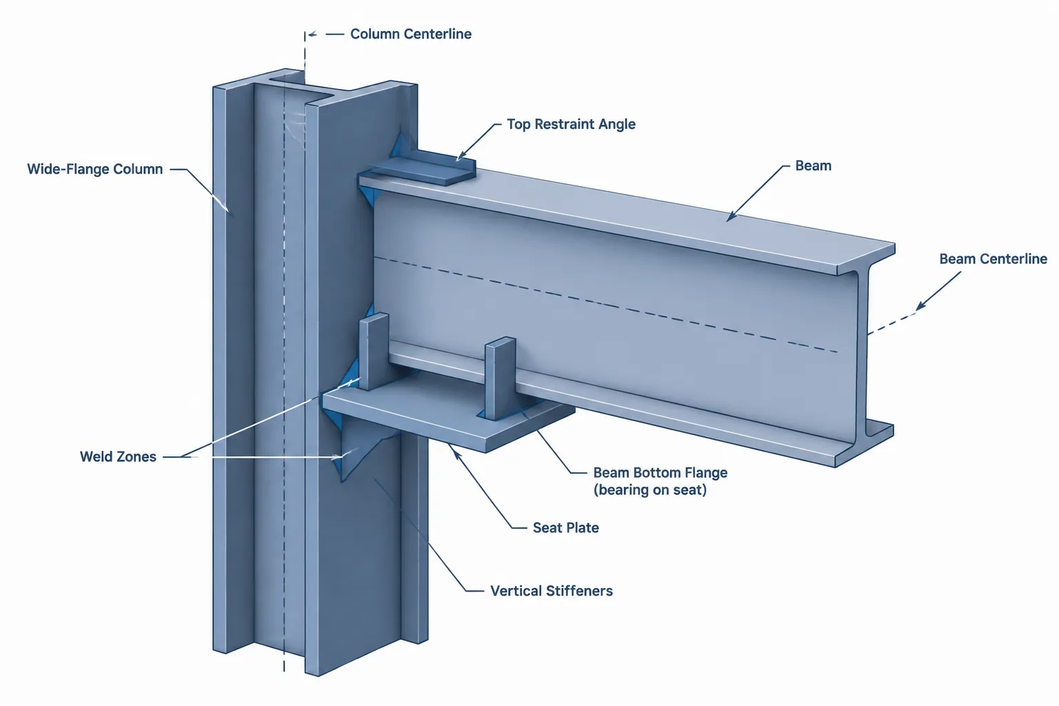
A seated connection places a structural component beneath the beam end. Depending on the design, that component may be a rolled angle, a plate, a built-up bracket, or a stiffened assembly. The beam bottom flange rests on the seat, creating a direct bearing surface during erection and in the completed structure.
A separate top angle, clip, plate, or other attachment may be provided near the beam top flange. Its purpose is not automatically the same as the seat’s purpose. It may stabilize the beam, maintain position, provide erection restraint, or transfer a specifically designed force. The drawings and connection design should make that role clear.
Common seated configurations include:
- Unstiffened seat angle: A rolled angle with one leg attached to the support and the projecting leg beneath the beam.
- Seat plate or bracket: A plate projecting from the support, sometimes combined with other plates or attachment elements.
- Stiffened seat: A seat plate supported by one or more vertical stiffener plates, creating a more direct load path into the support.
- Seat with top restraint: Any seated arrangement supplemented by a top angle, clip, plate, or similar positioning component.
Understanding the Load Path
The primary gravity reaction generally begins at the supported beam, passes through the bottom flange or adjacent beam region into the seat, and then enters the supporting column, girder, or other member. Each interface along that route matters.
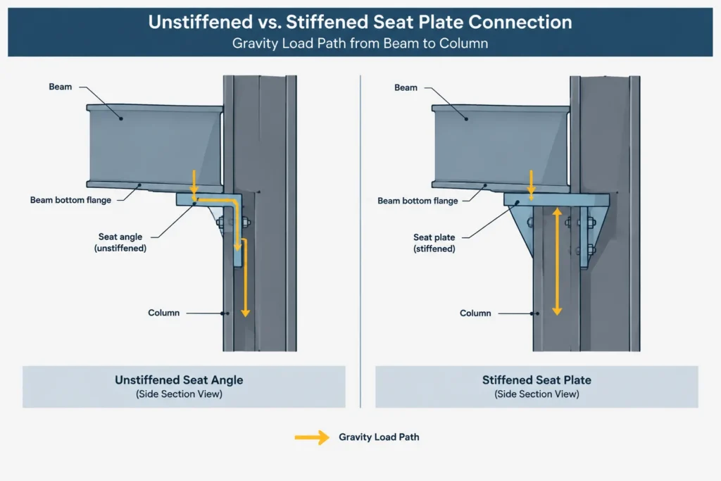
Beam-to-seat bearing
The beam does not transfer its reaction through an abstract centerline. It bears on a physical contact area. The detailer should identify where the bottom flange actually overlaps the seat and whether the seat remains beneath the flange after all setbacks, gaps, skew conditions, and tolerances are considered.
Nominal seat projection and effective bearing are not necessarily identical. A portion of the seat may be unavailable because of the support face, weld geometry, a stiffener location, or required clearance. Similarly, the beam end may not align with the outside edge of the seat.
Seat bending or bracket action
An unstiffened projecting angle or plate behaves differently from a seat reinforced by vertical plates. The horizontal leg of an angle can bend, while a stiffened seat can route force through the seat plate and stiffeners into the support. The connection engineer determines the relevant limit states and required geometry; the detailer must represent that geometry without inadvertently changing the intended structural mechanism.
Transfer into the supporting member
The support also requires evaluation. A seat attached to a column flange, column web, girder web, or HSS face interacts differently with each supporting surface. Local bending, yielding, weld force paths, stiffener requirements, and access can depend on both the support orientation and the seat location.
Key Geometry to Establish
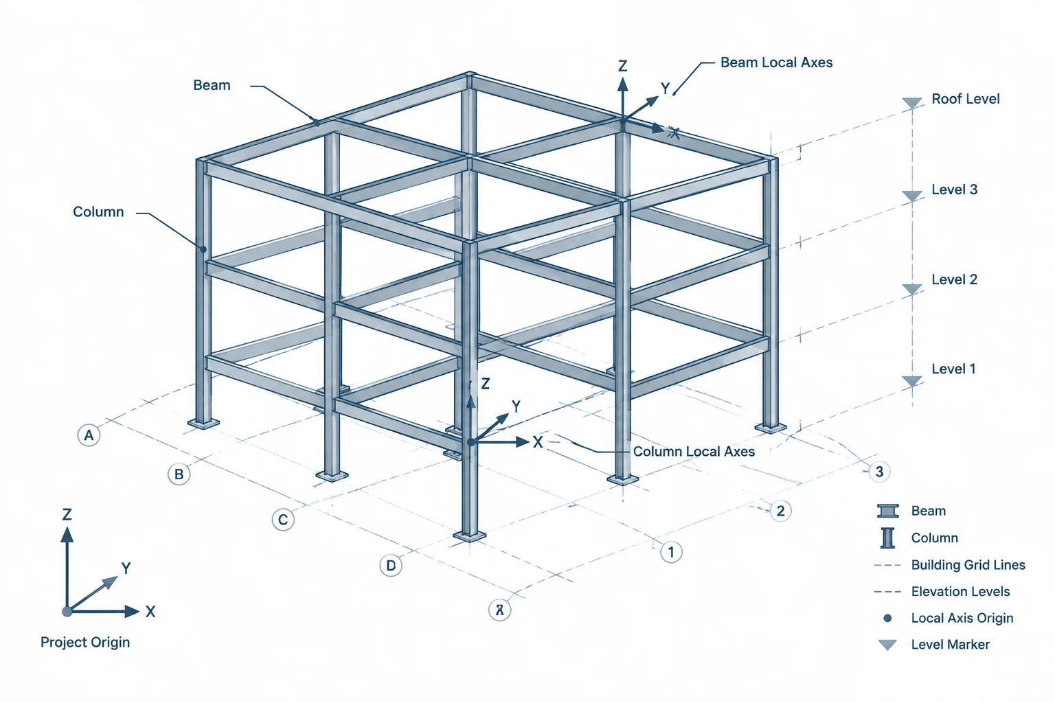
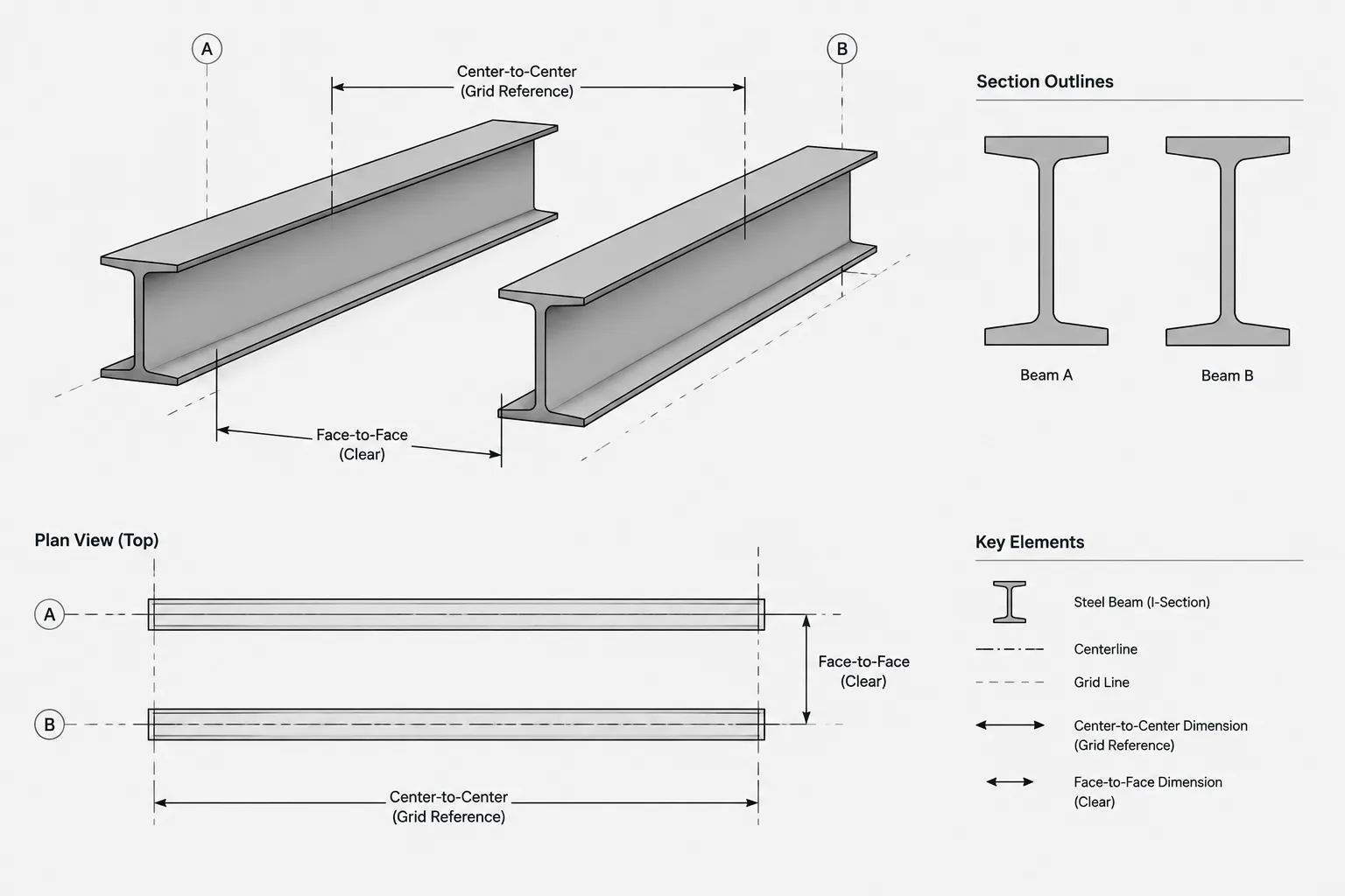
A reliable seat detail starts from controlling datums rather than from the visible edges of individual plates. Useful references often include the beam work line, support centerline, face of support, top-of-steel elevation, and beam bottom-flange elevation.
| Geometry item | Why it matters | Typical coordination question |
|---|---|---|
| Seat elevation | Controls the supported beam elevation | Is the elevation based on the seat top, beam top, or work point? |
| Seat projection | Influences bearing and erection placement | How much usable seat remains beyond the support and weld zone? |
| Beam end setback | Affects fit against the support | Is there enough clearance without sacrificing required bearing? |
| Seat width | Controls support beneath the flange | Does it fit the beam flange and avoid adjacent obstructions? |
| Stiffener position | Defines the bracket load path | Does it conflict with support fillets, welds, bolts, or backing? |
| Top restraint location | Affects stability and installation | Can it be installed without trapping the beam? |
Seat elevation versus beam elevation
If top of beam is the controlling project elevation, the seat top must be derived from the actual beam depth and orientation. A shape substitution can therefore move the required seat elevation even when the beam work line remains unchanged. Conversely, if the seat elevation is fixed before the beam size is finalized, the top-of-steel elevation may change.
Camber, slope, and end rotation assumptions can further affect how elevation information is interpreted. A drawing should avoid implying that every surface is level when the framing geometry says otherwise.
End clearance and bearing overlap
End clearance is useful for erection, but an excessive setback can reduce bearing overlap. Too little clearance may cause the beam end to contact the supporting member before it is fully seated. These dimensions should be coordinated as a system rather than selected independently.
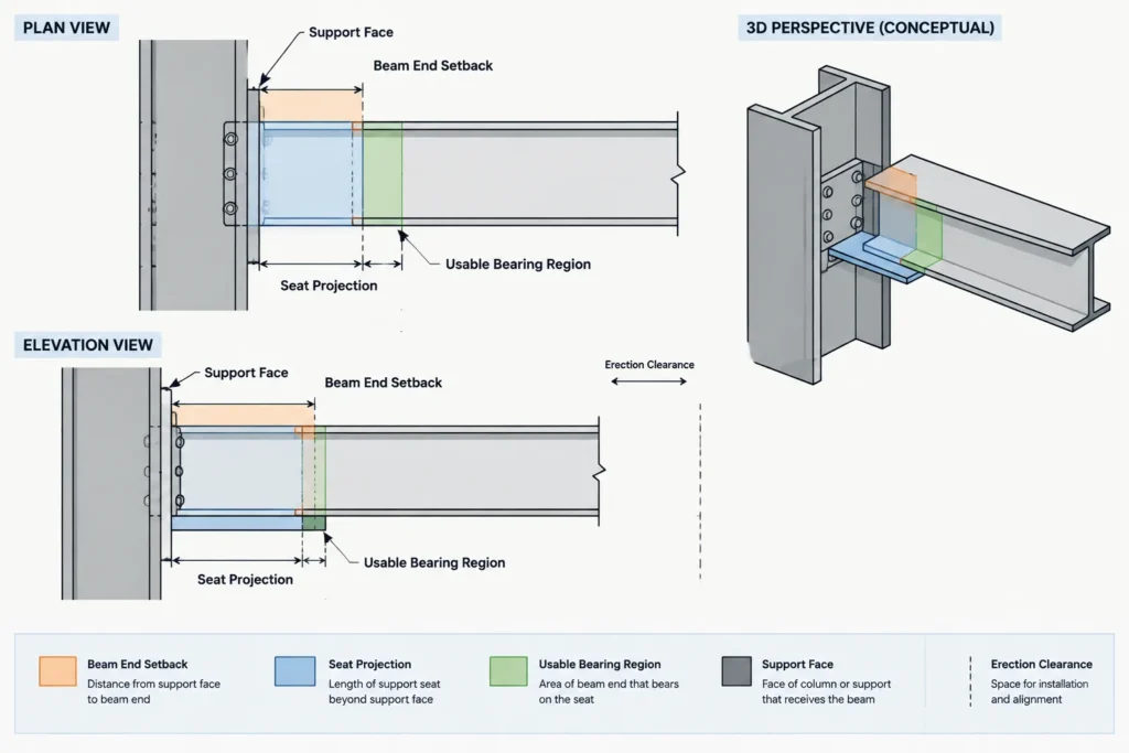
For skewed beams, the apparent gap in plan may not represent the minimum physical clearance across the entire beam end. The true cut plane, flange corners, and support face should be checked in plan and, when needed, in a three-dimensional model.
Rolled Fillets, Welds, and Physical Fit
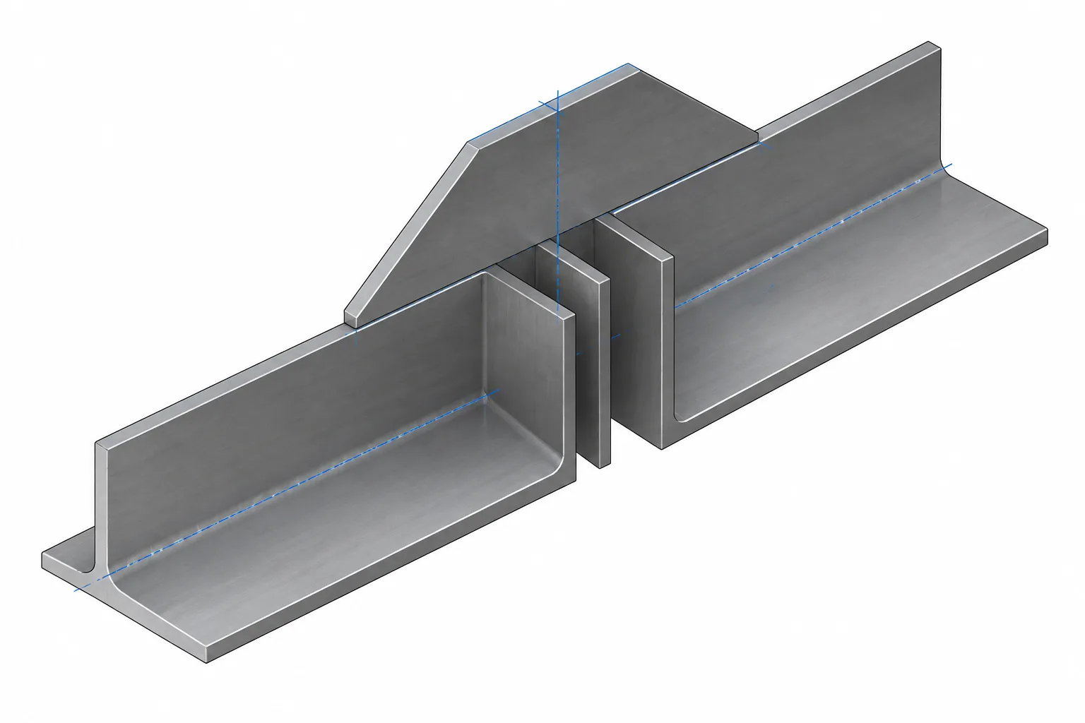
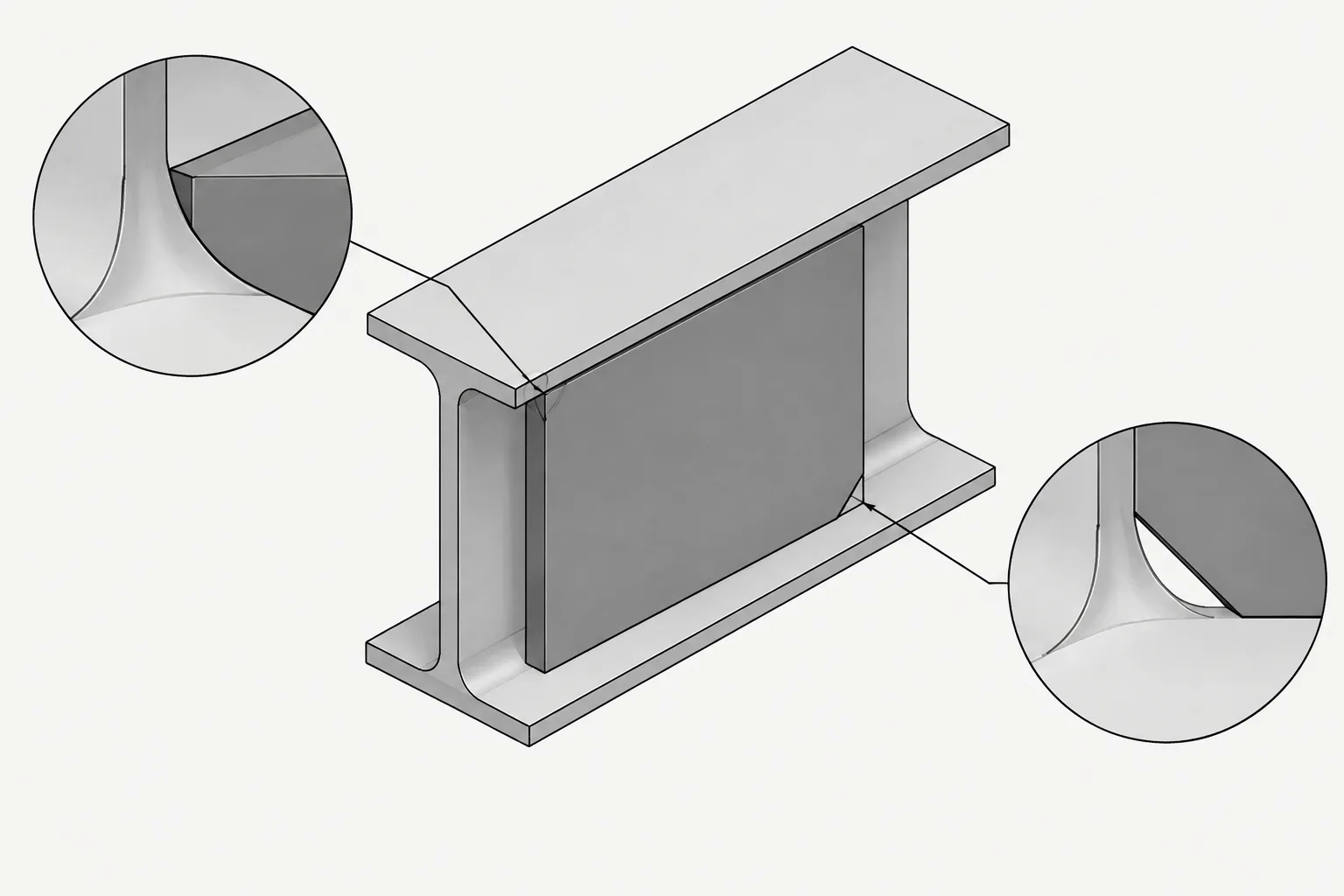
Idealized CAD outlines can conceal important fit-up conflicts. Rolled W-shapes, channels, and angles have curved transition regions rather than perfectly sharp internal corners. A stiffener plate placed too close to a rolled fillet may not fit as modeled unless it is shaped, clipped, or otherwise detailed for clearance.
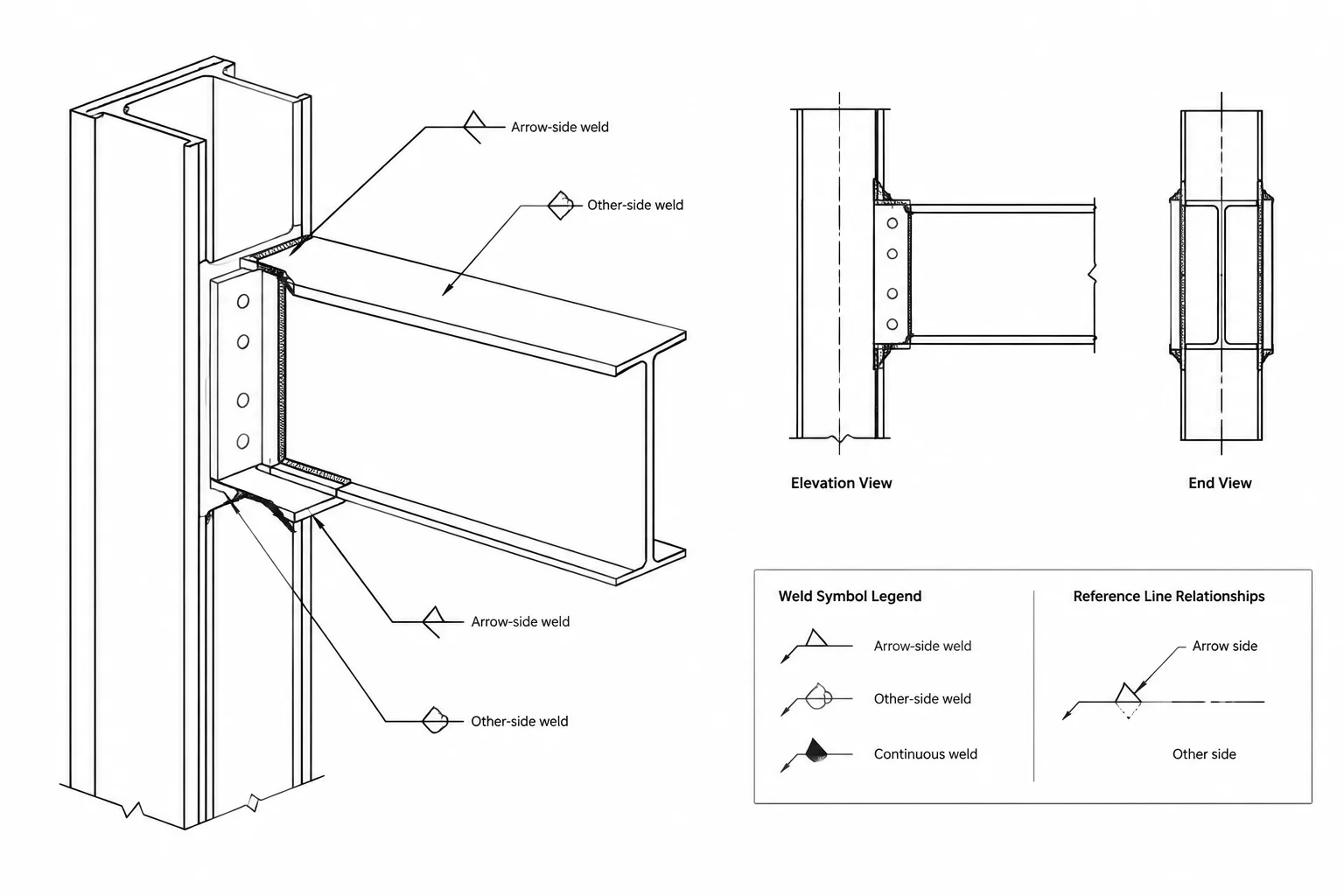
Welds occupy space as well. The beam bottom flange should not unintentionally land on a seat-to-support weld or on irregular weld reinforcement. Likewise, a vertical seat stiffener requires enough room for its welds without colliding with support fillets or nearby connection material.
The drawing should communicate intentional cuts or clearances. Fabricators should not have to infer whether a plate corner is meant to clear a radius, terminate short, or be fitted tightly.
Top Angles and Other Restraint Components
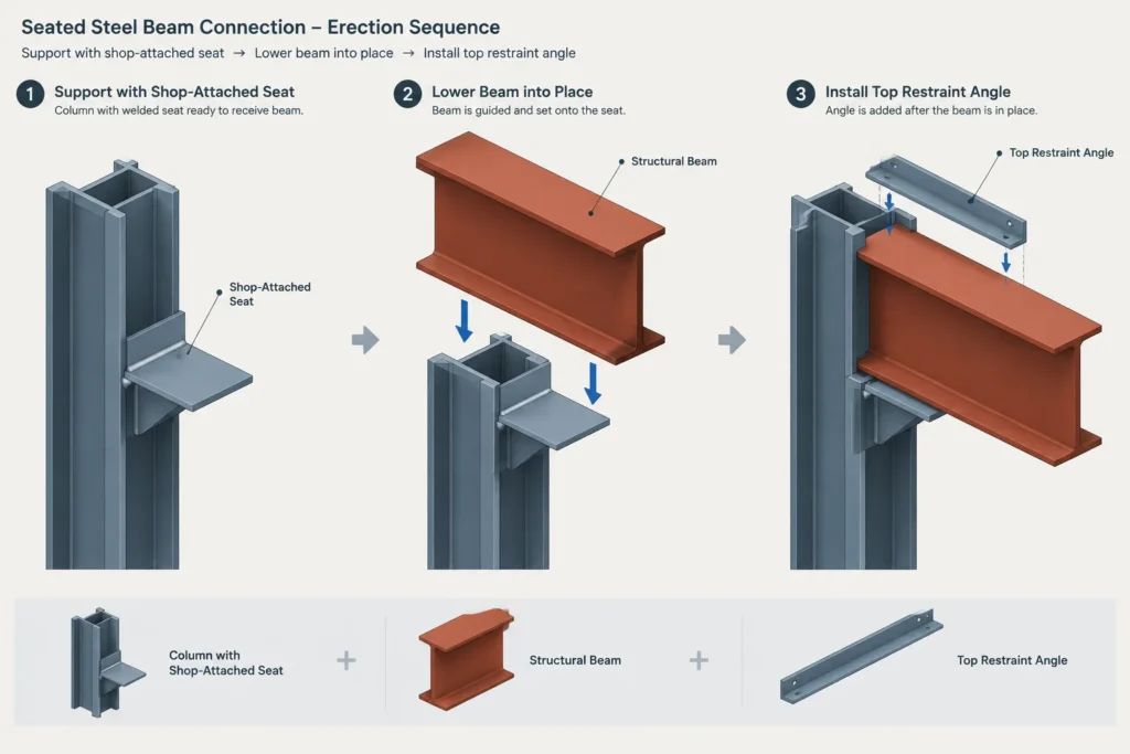
A top angle is often associated with a seated connection, but its function should not be assumed from appearance alone. It may hold the beam in position during erection, provide lateral restraint at the end, or participate in a designed force-transfer mechanism.
Detailing questions include:
- Is the top component shop-attached to the support or field-installed after the beam is seated?
- Does its position allow the beam to be lowered onto the seat?
- Are bolts and welds accessible in the intended erection sequence?
- Does it clear the beam flange, web fillet, deck, slab edge, or adjacent framing?
- Is a gap intentional, or is the component expected to contact the beam?
A restraint component installed too early can block erection. One installed later may require bolt or welding access that is unavailable after deck, bracing, or neighboring steel is in place. The detail should reflect a plausible installation sequence.
Seat Angles Versus Stiffened Seats
An unstiffened seat angle is compact and uses a readily recognizable rolled shape. Its projecting leg provides the bearing surface, while the vertical leg attaches to the support. Because the outstanding leg acts as a flexible projection, its behavior and attachment must be evaluated for the intended reaction.
A stiffened seat usually provides a seat plate with vertical stiffener plates beneath it. This arrangement can create a more direct bracket-like path into the supporting member, but it adds fabrication and detailing considerations. Stiffeners must fit the support, welds may intersect, and the assembly can obstruct bolts or neighboring connections.
The choice is not merely a drafting preference. It follows from the engineered connection, available supporting surface, fabrication approach, erection needs, and surrounding geometry.
Drawing and Model Information to Show
A seated connection detail should provide enough information to locate and fabricate the parts without relying on visual scaling. Depending on project practice, useful information may include:
- Supporting-member and supported-beam identification.
- Seat type and component marks.
- Seat top elevation or its relationship to a controlling beam elevation.
- Seat projection, width, thickness, and orientation as specified by the design.
- Beam end setback and bearing relationship.
- Stiffener quantity, location, orientation, and fit geometry.
- Bolt-hole locations and attachment faces where bolted construction is used.
- Weld locations and extents where welded construction is used.
- Top restraint position and shop or field installation status.
- Required clips, copes, corner treatments, and clearance notes.
In a model, the seat should be associated with the correct support face and elevation datum. Avoid using a visually convenient insertion point that becomes ambiguous after the support size or orientation changes.
Common Detailing Problems
- Modeling bearing without verifying contact: The beam appears above the seat, but a gap or interference exists in the actual geometry.
- Using overall projection as usable bearing: Weld zones, support faces, or clearances reduce the effective contact region.
- Ignoring rolled fillets: Stiffeners or angles clash with the root region of a rolled shape.
- Trapping the beam: A preinstalled top angle prevents the beam from being lowered into place.
- Changing the beam size without resetting the seat: The beam top elevation or bearing relationship no longer matches the design intent.
- Showing inaccessible welds or bolts: The connection can be drawn but not practically assembled.
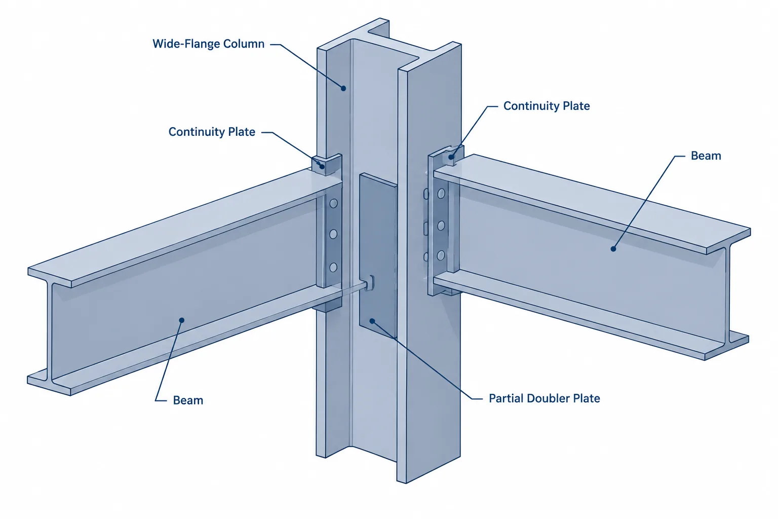
- Omitting support-side checks from coordination: A seat conflicts with continuity plates, web stiffeners, base-plate components, or another framing connection.
A Practical Coordination Workflow
- Confirm the framing datums. Establish the support face, beam work line, beam elevation, slope, and orientation.
- Place the actual beam section. Use verified shape geometry, including relevant flange and fillet regions.
- Set the bearing relationship. Coordinate seat elevation, beam setback, seat projection, and physical contact.
- Add the support-side components. Model angles, plates, stiffeners, bolts, and weld envelopes at an appropriate level of detail.
- Test the erection path. Determine whether the beam can be lowered, shifted, and secured in the intended sequence.
- Check adjacent work. Review deck, slab edges, braces, column splices, base details, and other connections.
- Verify design information. Ensure that modeled and drawn parts match the connection design rather than a generic library detail.
- Review after revisions. Recheck elevations, bearing, clearances, and component marks whenever member sizes or support orientations change.
Final Perspective
Steel beam seat connections provide a clear physical support point and can simplify beam placement during erection, but their apparent simplicity should not obscure the coordination required. Bearing area, end clearance, seat projection, support attachment, rolled fillets, weld space, top restraint, and erection sequence all interact.
The most useful detail is not simply one that looks correct in elevation. It is one that preserves the engineered load path, establishes unambiguous datums, represents physical fit, and can be fabricated and erected in a realistic sequence. Final dimensions and connection requirements should always be verified against the project documents and approved connection design.