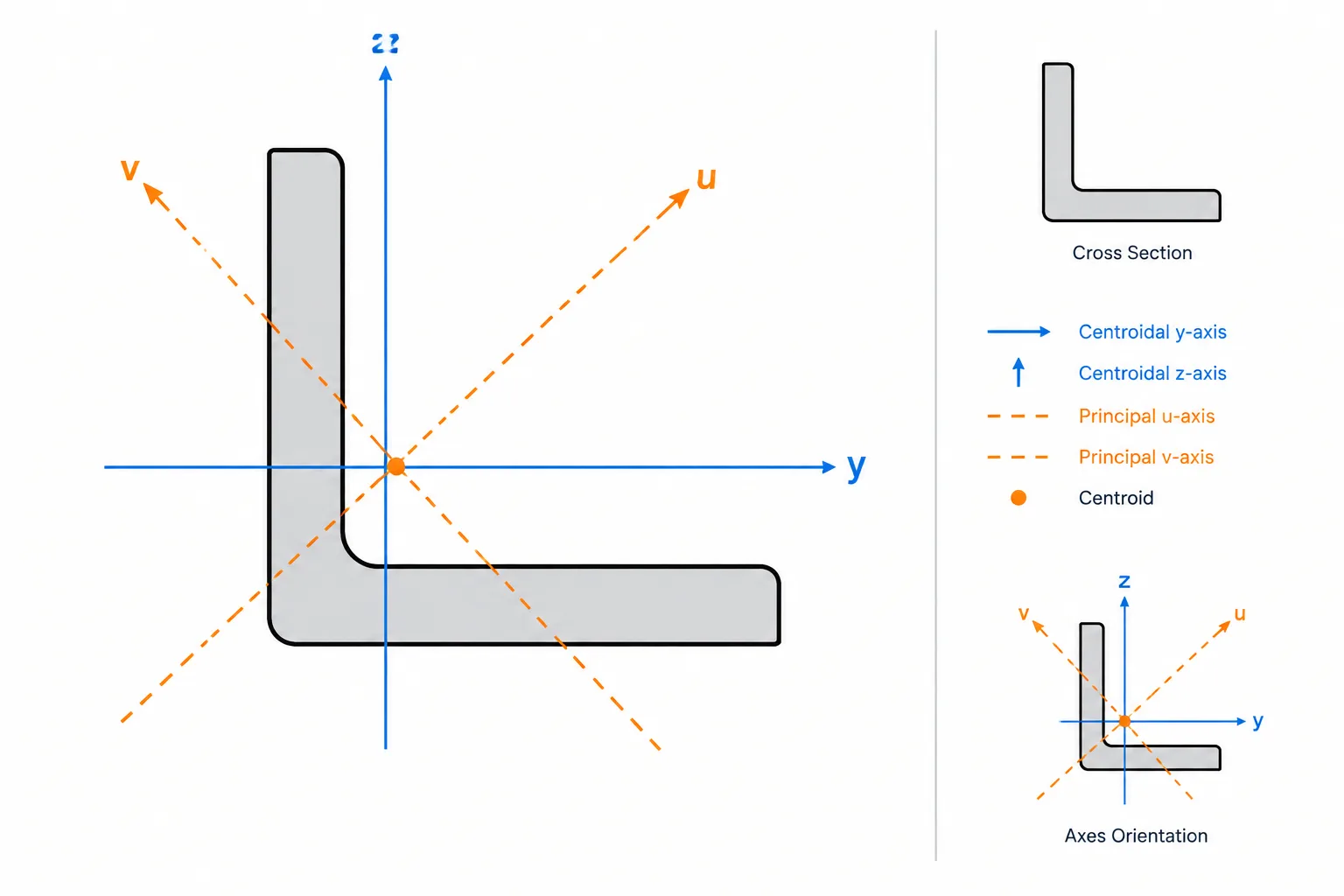
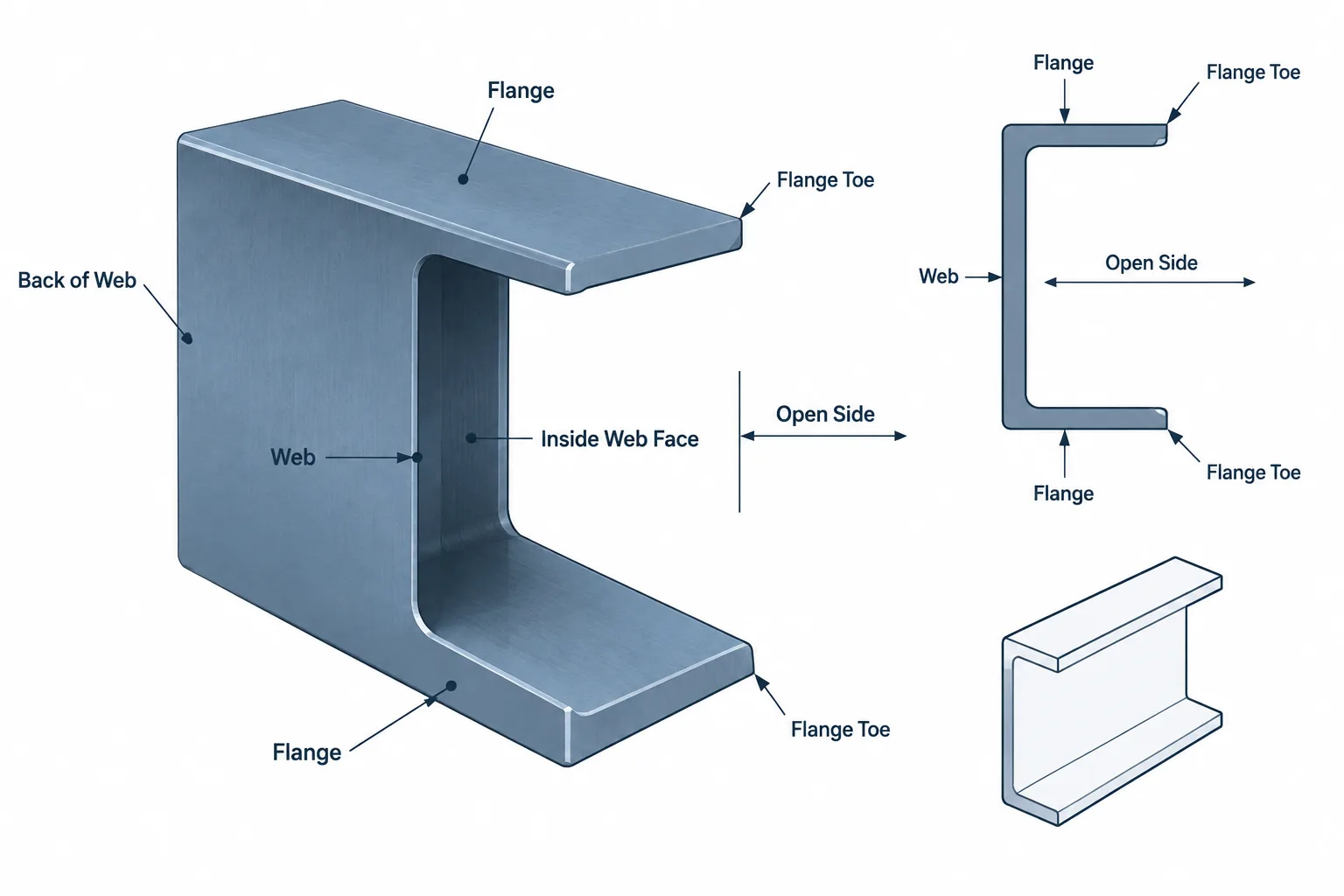
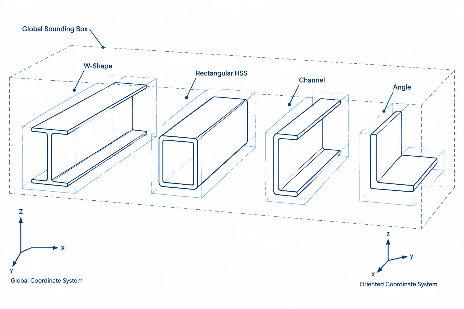
The PFC 200x75x23 is a parallel flange channel section used as a compact, open structural steel profile. This reference brings together the section dimensions, mass information, and standard context needed for early specification, drafting, and comparison with other channel sections.
Use the dimensional data below as the authoritative reference for this profile. The downloadable DWG can support CAD coordination, but the section should still be checked against the project’s material specification, loading, connection arrangement, and design requirements before it is used in a structural application.
PFC 200x75x23
Parallel Flange Channels
refer to : EN 10365:2017
a European standard that defines the dimensions, tolerances, and sectional properties for hot-rolled steel channels, I-beams, and H-beams used in construction and engineering. It ensures uniformity and compatibility across European structural steel products.
Dimension : 200x75x6x12.5
Depth : 200 mm
Width : 75 mm
Web Thickness : 6 mm
Flange Thickness : 12.5 mm
Root Fillet Radius : 12 mm
Sectional Area : 29.9 cm2
Unit Weight : 23.5 kg/m
How to read the PFC 200x75x23 designation
The designation identifies a parallel flange channel by its nominal depth, flange width, and approximate mass class. The detailed source data provides the actual listed depth, width, web thickness, flange thickness, root fillet radius, sectional area, and unit weight for this profile.
What the listed dimensions describe
- Depth and width: These define the overall envelope of the channel and are important when checking clearance, fit-up, and orientation in a drawing.
- Web and flange thickness: These describe the principal plate elements of the open section and affect detailing, connection geometry, and section-property calculations.
- Root fillet radius: The curved transition between the web and flange should be allowed for when a connection, plate, or adjacent component bears against the section.
- Sectional area and unit weight: These are useful for material takeoffs and reference calculations. They do not by themselves establish a member’s allowable load or suitability for a particular design.
Using the PFC reference in design and drafting
Parallel flange channels are often compared by their geometric properties, orientation, and connection requirements. When selecting this profile, confirm the required steel grade, fabrication limits, corrosion protection, end conditions, restraint, and load effects through the applicable design process. The profile data can support that process, but it is not a substitute for member, connection, or stability verification.
For drafting workflows, the downloadable DWG is useful as a starting point for layout and detailing. Check the drawing units, insertion scale, section orientation, and any project-specific detailing conventions before incorporating it into a production model.
Standard context
The source identifies EN 10365:2017 as the reference for the section dimensions, tolerances, and sectional properties. Treat the standard reference and the local numeric content as complementary: the standard provides the profile framework, while the project specification determines how the section is purchased, fabricated, protected, and designed.
Frequently asked questions
What is a PFC section?
PFC means parallel flange channel. It is an open steel channel with flanges arranged parallel to one another, making it distinct from tapered-flange channel forms.
What does PFC 200x75x23 mean?
The designation describes the channel’s nominal size and mass class. Always use the detailed dimensions and unit weight in the reference entry when preparing drawings, takeoffs, or comparisons.
What information is provided for this PFC?
The reference lists the channel dimensions, web and flange thicknesses, root fillet radius, sectional area, unit weight, and the stated EN 10365:2017 reference.
Can the PFC 200x75x23 be used directly for structural design?
No profile designation alone establishes structural suitability. Member resistance, stability, connections, material grade, loading, restraint, and the governing design requirements must be verified by a suitably qualified engineer.
Is a CAD file available?
Yes. The source includes a DWG download for the PFC 200x75x23 profile. Review units, scale, orientation, and project drafting requirements before use.