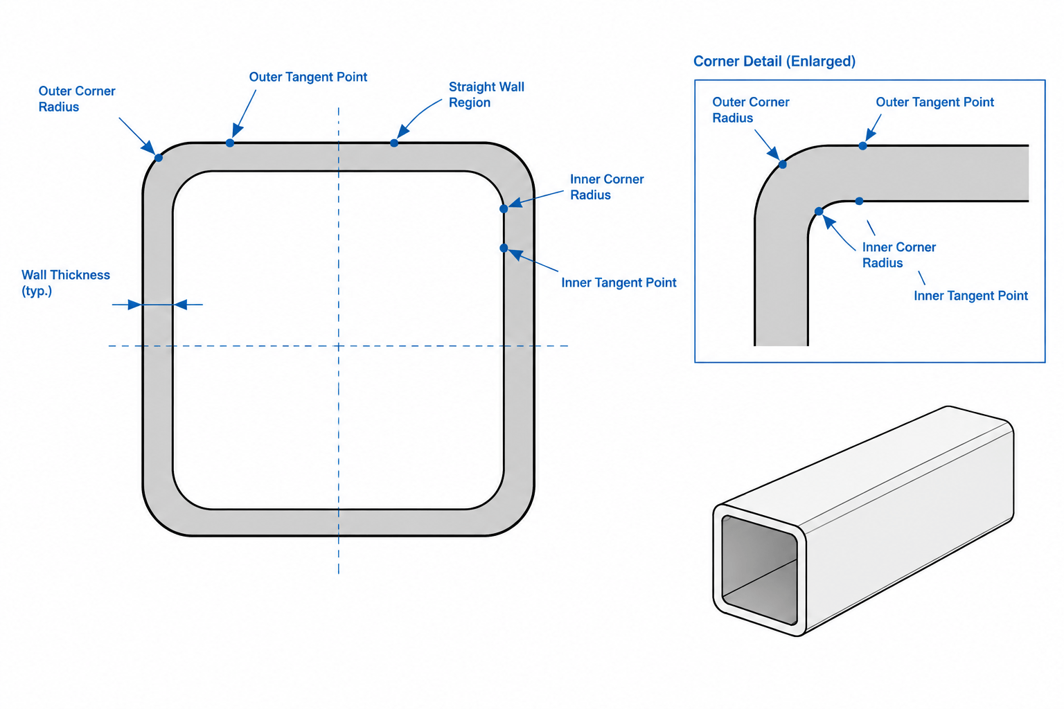
Square and rectangular hollow structural sections look simple in plan and section views, but their rounded corners create important detailing questions. A generic CAD rectangle with sharp corners may be adequate for a preliminary framing plan, yet it can be misleading when plates, bolts, welds, slots, or adjacent members approach an HSS corner.
Understanding the HSS corner radius is therefore less about drawing a visually perfect tube and more about knowing when the curved region affects fabrication or connection geometry. Designers and detailers should distinguish between overall section dimensions, wall thickness, tangent points, flat wall regions, and the actual manufactured corner profile.
The basic geometry of square and rectangular HSS
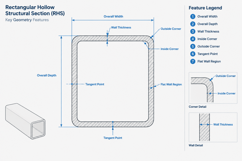
A square or rectangular HSS cross-section is typically identified by its overall outside dimensions and a wall-thickness designation. The outside dimensions are measured between opposite exterior faces. They are not dimensions to the wall centerline or to the inside opening.
The four walls transition through rounded corners rather than meeting as sharp ninety-degree intersections. Each corner has an exterior curve and an interior curve. In simplified CAD geometry, these curves may be represented as concentric arcs separated by the modeled wall thickness. Real manufactured corners are not necessarily perfect circular arcs, and their exact profiles can vary within applicable production tolerances.
Useful geometric terms include:
- Outside depth: the overall exterior dimension in one principal direction.
- Outside width: the overall exterior dimension perpendicular to the depth.
- Wall thickness: the thickness used for the applicable design, reference, or detailing purpose.
- Outside corner radius: the exterior curved region connecting adjacent walls.
- Inside corner radius: the corresponding curve around the interior opening.
- Tangent point: the location where a straight wall transitions into the corner curve.
- Flat width: the straight portion of a wall between the tangent regions at its ends.
Why flat width matters
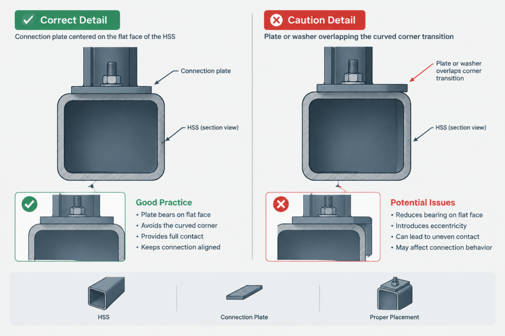
The overall face of an HSS is wider than its truly flat bearing or attachment region. Near each edge, the wall curves toward the adjacent face. A plate, bolt head, washer, weld, or connected member placed in this transition may not sit as expected on a flat surface.
This distinction matters in several common situations:
- Locating bolt holes near the edge of an HSS face.
- Checking washer or bolt-head seating.
- Placing longitudinal welds along an HSS wall.
- Fitting clip angles, shear tabs, or other plates against a face.
- Designing slots for through-plates or knife plates.
- Detailing cap plates and base plates around outside corners.
- Checking clearance between an HSS corner and another steel shape.
A plate dimensioned to the full outside width may extend over both curved corner regions. That may be intentional for a cap or base plate, but it should not be confused with the available flat wall width. Conversely, a component intended to bear only against the straight wall region should be checked against verified corner geometry.
Corner radius is not a universal fixed value
It is risky to assume that every HSS with the same outside dimensions has an identical corner radius. Corner geometry depends on the forming process, wall thickness, production tolerances, and the source used to define the section. Published shape data may provide a detailing radius, a maximum radius, a typical value, or no corner-radius field at all.
A radius copied from an unrelated section, a generic CAD library, or a visually similar tube should not control fabrication-sensitive work. When corner clearance is important, consult the project criteria and current verified product or reference data. If the connection has little tolerance for variation, the detail may also require coordination with the fabricator or material supplier.
HSS dimensions that should not be mixed
| Dimension or property | What it describes | Common detailing mistake |
|---|---|---|
| Overall width or depth | Distance between opposite outside faces | Treating it as the width of the flat wall region |
| Wall-thickness designation | The listed thickness associated with the section designation | Assuming it is automatically the correct value for every design or fabrication calculation |
| Design thickness | The thickness used under the governing design method and project criteria | Using it to predict exact shop fit-up without considering tolerances |
| Inside opening | The clear region enclosed by the walls and inside corners | Modeling it as a sharp-cornered rectangle |
| Corner radius | The curved transition between adjacent walls | Applying an unverified radius from a generic block |
| Flat width | The straight wall length between corner tangent regions | Equating it to the overall face dimension |
Choosing the right CAD representation
The appropriate level of HSS detail depends on what the drawing or model must communicate. More geometric detail is not always better. It can increase file complexity while suggesting a level of manufacturing precision that the source data does not support.
Centerline representation
A centerline or single-line member is usually sufficient for framing diagrams, early layouts, and views where section boundaries do not affect coordination. The shape designation and orientation carry more useful information than a detailed corner profile in these views.
Outside-envelope representation
A rectangular outside envelope is useful for general arrangement, clash checking, and many elevation or plan views. Rounded exterior corners may be omitted when they do not affect the purpose of the drawing. The model should still preserve the correct overall width and depth from a verified section source.
Simplified hollow profile
A hollow profile with rounded inside and outside corners is appropriate for section views, connection details, and fabrication-oriented modeling. The radii should be identified as representative unless they come from an authoritative project source. Avoid deriving critical clearances from an illustrative profile.
Fabrication-sensitive geometry
Exact or bounding corner geometry may be needed when a component wraps around the corner, enters the HSS interior, or depends on a close fit. In these cases, a generic section block is only a starting reference. Connection geometry should be checked against applicable tolerances, weld requirements, erection needs, and fabricator input.
A practical CAD workflow
- Confirm the designation. Verify the HSS type, outside dimensions, and thickness information against the project source rather than reading them from an old drawing block.
- Identify the drawing purpose. Decide whether the view needs a centerline, an outside envelope, a representative section, or fabrication-sensitive geometry.
- Build from outside faces. Establish the overall width and depth before adding wall thickness or corner curves. This helps prevent centerline-based dimension errors.
- Add corners deliberately. Use a verified radius when available. Otherwise, label or manage the profile as schematic and avoid using it for critical fit-up.
- Check tangent regions. Review plates, fasteners, welds, and adjacent parts that approach the curved corners.
- Separate reference geometry from connection geometry. Keep the generic HSS profile distinct from slots, copes, plate edges, and other fabricated features.
- Dimension functional relationships. Dimension connection work points, plate locations, and required clearances rather than relying on users to scale the corner profile.
Connection details affected by HSS corners
Cap plates and base plates
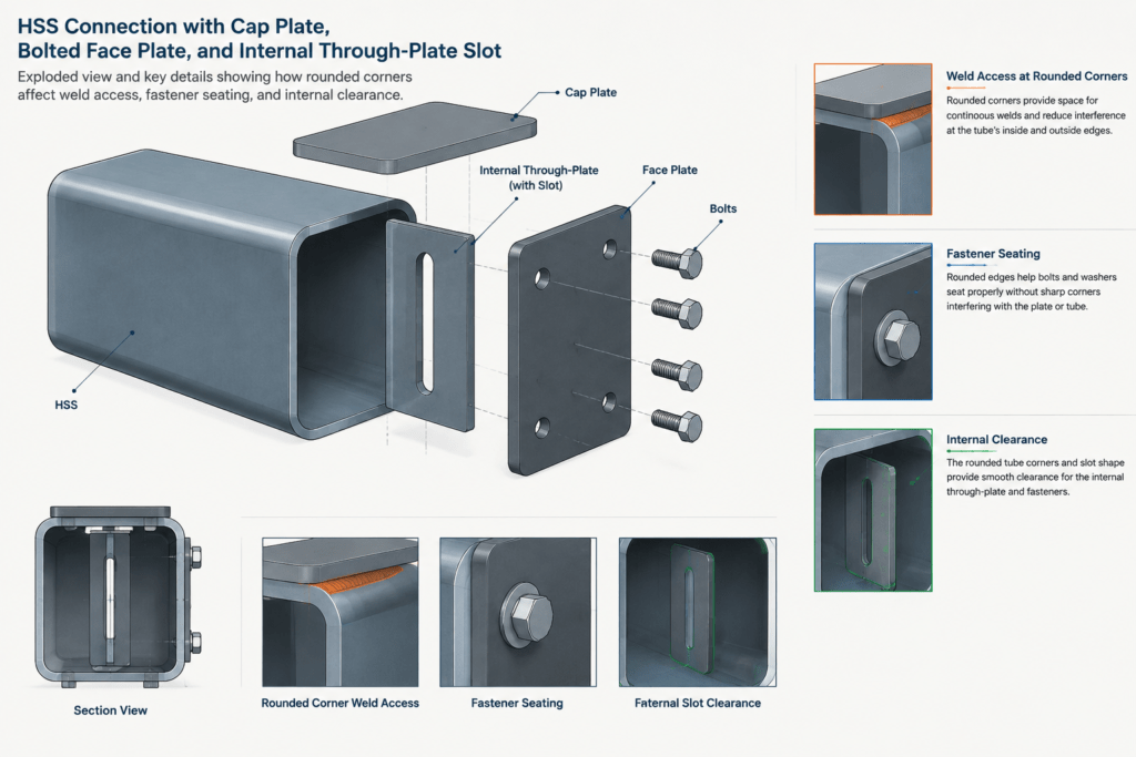
A cap or base plate commonly extends beyond the HSS outside faces, so the rounded exterior corners may not control the plate outline. They can still influence weld access, weld termination, and the appearance of the joint. A flush plate requires greater attention to the relationship between its edge and the HSS corner.
Through-plates and knife plates
Components passing through an HSS depend on the inside opening, not just the outside width minus two listed wall thicknesses. Rounded interior corners reduce clearance near the edges of that opening. Slots should not be detailed from an idealized sharp-cornered void when fit-up depends on the actual corner region.
Bolted attachments
Fasteners located on an HSS face need sufficient room for holes, washers, bolt heads, installation tools, and any required reinforcement. A fastener center may appear to lie within the overall face while its washer overlaps the curved transition. Section views are often more informative than plan views for detecting this issue.
Wraparound and fitted parts
Saddles, collars, bent plates, and fitted stiffeners are especially sensitive to corner shape. A part drawn to match one idealized radius may not fit every produced member represented by the same designation. Practical details may need clearance, adjustment provisions, or shop verification rather than a theoretically exact profile.
Do not calculate section properties from a rough CAD outline
A simplified HSS block is useful for drafting, but it should not replace verified section-property data. Small changes in wall thickness and corner treatment affect area, weight, moments of inertia, section moduli, torsional properties, and other values. Properties calculated from a sharp-cornered tube or an arbitrary fillet model may not match published properties for the designated HSS.
Use trusted section tables or project-approved data for engineering properties. Use CAD geometry to communicate member location, orientation, interfaces, and connection configuration. Keeping those purposes separate avoids false precision and makes HSS details easier to review.
Key detailing takeaway
An HSS face consists of a straight central region plus curved corner transitions. Overall width is therefore not the same as usable flat width, and the inside opening is not simply a sharp-cornered rectangle. For ordinary framing drawings, simplified geometry is often appropriate. When a connection approaches, crosses, or fits around a corner, verified corner information and fabrication-aware clearance become important.


