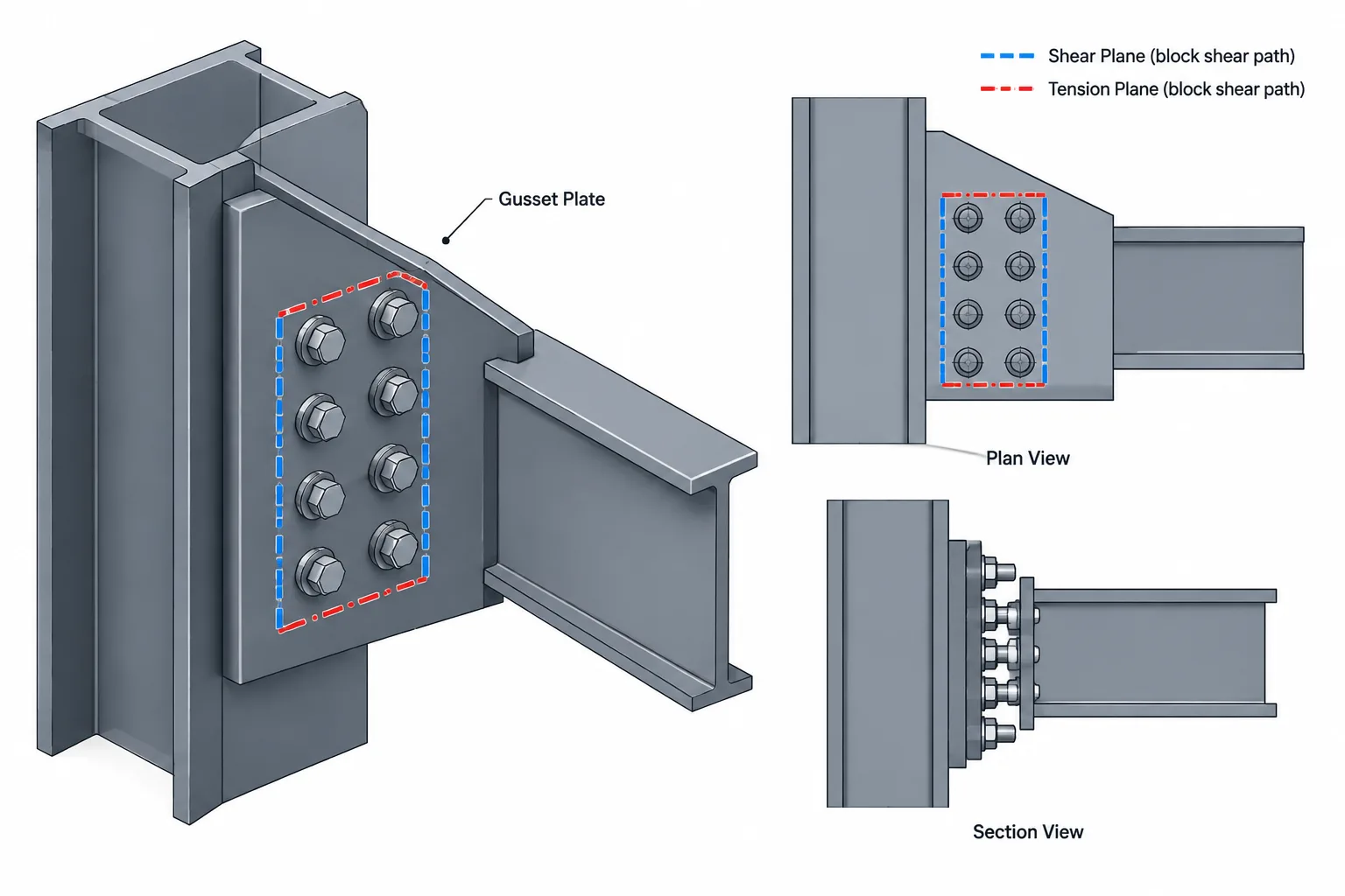
Block shear is a connection limit state in which a block of material can pull away from the rest of a steel component. The potential failure path commonly passes along one or more planes parallel to the applied force and across a plane approximately perpendicular to that force. Bolt holes may reduce portions of the resisting area, so the critical path is not always obvious from the outside edges of the part.
For designers and detailers, the first challenge is geometric: identify every credible block that could separate around the bolt group. This requires more than drawing a rectangle around the bolts. Connected legs, free edges, member ends, cope lines, staggered holes, and nearby cuts can all change the path. Strength calculations and resistance factors must follow the governing design standard, but a disciplined drawing and CAD review can prevent many path-selection errors before calculation begins.
What a block shear path looks like
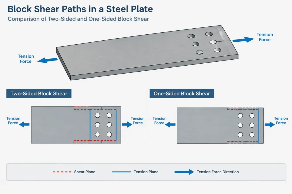
A typical block shear path resembles a U-shaped or J-shaped boundary around a group of fasteners. The longitudinal sides of the block are treated as shear planes, while the transverse end of the block is treated as a tension plane. The applied force tends to pull the enclosed material away as a connected block.
The path may include:
- A shear plane between a free end and a transverse bolt line.
- Two shear planes on opposite sides of a bolt group.
- A tension plane crossing a row of holes.
- A tension plane running from a hole to a free edge.
- An interior path defined by the geometry of the connected element rather than its full width.
Block shear is therefore different from simply checking the net section across the entire part. A net-section path crosses the member and represents rupture across that section. A block shear path encloses a localized piece of material adjacent to the connection.
The four area concepts behind the check
Block shear calculations distinguish between shear and tension planes and between gross and net areas. The exact design expression depends on the governing standard and the connection configuration, but the geometry is organized around four concepts.
| Area concept | Practical meaning | Typical geometric basis |
|---|---|---|
| Gross shear area | Undiminished material along the candidate shear path | Shear-path length multiplied by the relevant thickness |
| Net shear area | Remaining material along the shear path after applicable hole deductions | Net path length multiplied by thickness |
| Gross tension area | Undiminished material across the end of the candidate block | Tension-path length multiplied by thickness |
| Net tension area | Remaining material across the tension plane after applicable hole deductions | Net transverse path length multiplied by thickness |
The gross and net lengths must be measured on the same physical path being evaluated. Combining a shear length from one candidate block with a tension length from another creates a result that does not represent an actual failure mechanism.
How to trace a candidate path
1. Establish the force direction
Begin by showing how force enters and leaves the connected part. The shear planes generally extend roughly parallel to that force, while the tension plane closes the block across it. If the connection transfers force in more than one direction, separate loading cases or alternative paths may require review.
2. Mark free edges and discontinuities
Identify the member end, plate edges, angle toes, cope boundaries, slots, notches, and other cuts. A block must reach a free boundary or another discontinuity that allows the material to separate. Nearby geometry can create a shorter path than the one implied by the overall part outline.
3. Locate the controlling bolt lines
Draw centerlines through the fastener rows. Determine which bolt line can form the transverse boundary of the block and which holes lie along the longitudinal sides. Do not assume the outermost row automatically controls. An interior row, staggered pattern, or uneven edge distance may define another credible path.
4. Close the block
Trace a continuous boundary consisting of the relevant shear and tension segments. If the proposed line does not enclose a piece of material that could physically pull away, it is not a complete block shear path.
5. Repeat the process
Connections can have several possible blocks. Check left-side, right-side, full-width, one-sided, interior, and staggered alternatives where they are geometrically possible. Symmetry can simplify the review, but it should be confirmed rather than assumed.
Common configurations
Plates and gusset plates
A plate connected near its end often has a block bounded by longitudinal planes from the end to a transverse bolt row. A centered bolt group may create two similar shear sides, while a group near one plate edge may permit a one-sided path. Tapered gussets require special attention because the available width changes along the connection.
Single angles
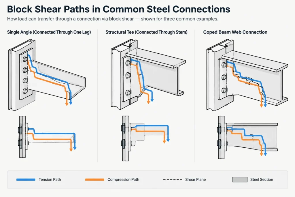
For an angle connected through one leg, trace paths within the connected leg rather than treating the unfolded angle as a flat plate of combined leg widths. The heel, toe, member end, and bolt arrangement define the available material. The outstanding leg affects the member behavior and load path, but it does not automatically form part of every candidate block.
Double angles
Each angle is a separate physical component unless the connection geometry establishes another load-transfer mechanism. Mirrored angles may have similar paths, but differences in cuts, gages, bolt access, or end preparation can make their net geometry different.
Structural tees
A tee connected through its stem may develop a path in the stem near the member end. A tee connected through its flange can have different one-sided or two-sided paths depending on the bolt layout and free edges. The stem-to-flange junction should not be treated as a sharp rectangular corner when judging detailing clearance, even though simplified design geometry may use defined reference lines.
Channels and coped beams
Channel web connections can resemble plate connections, but flange projections and root geometry affect access and detailing. At a coped beam end, the cope boundary creates a nearby free surface and can shorten a possible path around web bolts. The block shear review should use the actual remaining web geometry rather than the uncoped shape depth.
Hole deductions and staggered layouts
Net-area deductions depend on the applicable hole geometry and design provisions. A CAD circle representing a bolt shank is not necessarily the dimension used for a net-area calculation. The drawing should clearly identify the specified hole type, and the engineer should apply the deductions required by the governing standard.
Staggered holes require additional care because the shortest-looking orthogonal path may not be critical. A zigzag path can pass between offset holes, and the applicable net-section treatment depends on its spacing geometry. Keep the following items distinct:
- Actual hole shape shown for fabrication.
- Nominal fastener size.
- Specified hole classification.
- Calculation deduction required by the design rules.
- Center-to-center pitch and transverse gage used to describe a staggered path.
Do not resize fabrication holes merely to make a CAD area calculation reproduce a design deduction. The fabrication model and the engineering calculation can represent different purposes and should be documented accordingly.
CAD workflow for reviewing block shear geometry
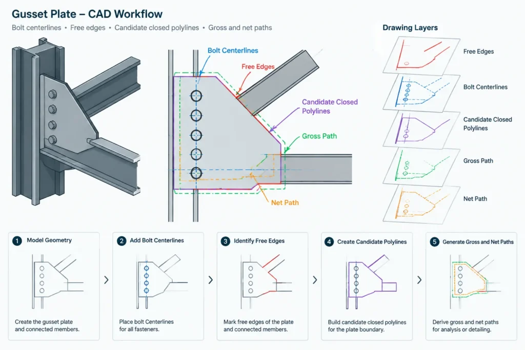
A useful CAD check can be performed without turning the drawing into a design program. Create a temporary review layer and trace each candidate block as a separate closed polyline. Use different colors or line patterns for shear and tension segments, and label the corresponding holes.
A practical workflow is:
- Orient a copy of the connected part so the primary force direction is clear.
- Show the actual part boundary, holes, slots, copes, and notches.
- Add bolt-row and hole centerlines.
- Trace each plausible separating block with a closed polyline.
- Dimension gross path lengths from controlled work points or edges.
- Record which holes intersect each path.
- Compare mirrored paths rather than assuming they match.
- Save the engineering trace separately from fabrication geometry.
CAD area commands can help confirm polygon geometry, but they do not determine which gross or net areas are valid under a design standard. They also cannot decide whether a path represents a physically credible failure mechanism. Engineering judgment remains necessary.
Frequent detailing and review errors
- Checking only a centered U-shaped path: Edge-adjacent bolt groups can also have shorter one-sided paths.
- Using overall plate width: The tension plane belongs to the candidate block, not automatically to the full component width.
- Ignoring copes and notches: A cut can move the free boundary closer to the bolt group.
- Applying every hole deduction twice: Hole intersections must be assigned consistently to the selected path and calculation method.
- Assuming symmetric parts have symmetric net geometry: Slots, skewed ends, handed cuts, or unequal edge distances can invalidate that assumption.
- Mixing modeled and design hole sizes: The geometry used for fabrication display may not be the required calculation deduction.
- Reviewing the connection in isolation: Force direction and load transfer determine which paths are relevant.
A coordination checklist
Before releasing a connection detail, confirm that the force direction is understood, all free edges and cuts are modeled, hole types are identified, and every credible block path has been considered. Verify that the engineer’s calculation geometry matches the final bolt layout and member end preparation. If holes, edge distances, plate shape, cope geometry, or connection orientation change, repeat the review rather than carrying forward the original result.
Block shear is a strength calculation, but its foundation is accurate connection geometry. Clear drawings, controlled dimensions, and explicit path tracing help designers and detailers discuss the same physical mechanism—and make revisions easier to check.