The first moment of area, commonly written as Q, is an important but often misunderstood section property. Unlike area, moment of inertia, or section modulus, Q is usually not a single fixed value for an entire steel shape. It depends on the location where shear stress or shear flow is being evaluated.
This makes Q especially relevant when examining shear through a W-shape web, force transfer between parts of a built-up member, or the distribution of shear in channels, tees, angles, and hollow structural sections. It is also a property that can be calculated efficiently in CAD—provided the correct portion of the cross section and the correct reference axis are used.
What Is the First Moment of Area?
The first moment of area is the sum of each small area multiplied by its perpendicular distance from a selected axis. For an area measured relative to a centroidal x-axis, it may be expressed conceptually as:
Q = ∫ y dA
For an area that can be divided into simple components, the equivalent calculation is:
Q = Σ(Ai yi)
Here, Ai is a component area and yi is the perpendicular distance from that component’s centroid to the reference axis. The resulting units are length cubed, such as in.3 or mm3.
Q is also called the statical moment of area in some references. It should not be confused with a torsional property, a load, or the moment of inertia I.
Why Q Is Not Usually a Single Table Value
Moment of inertia describes the distribution of the entire section about an axis. By contrast, Q in a transverse-shear calculation represents only the portion of the section on one side of the location being investigated.
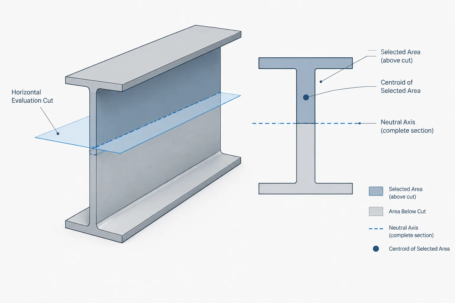
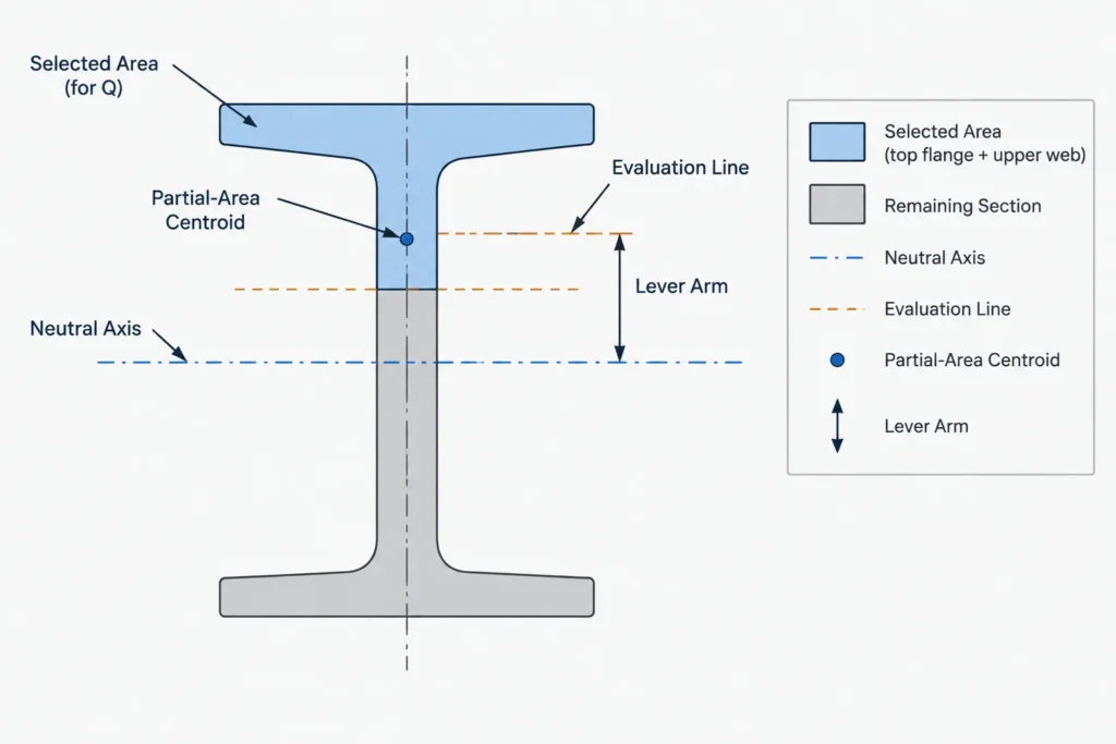
Imagine a horizontal cut through the web of a W-shape. To calculate Q at that cut, select either the cross-sectional area above the cut or the area below it. Find the centroid of that selected area, then multiply the selected area by the distance from its centroid to the neutral axis of the complete section.
If the cut moves, the selected area changes. Its centroid also changes. Therefore, Q changes through the depth of the member.
The first moment of the entire section about its own centroidal axis is zero because areas on opposite sides of the axis have opposite signed distances. That zero result is not the Q used in the usual shear formula. The shear calculation uses the area on one side of the evaluation line.
How Q Appears in Shear Stress and Shear Flow
For appropriate beam-section calculations, longitudinal shear stress is commonly represented by:
τ = VQ / (I t)
The associated shear flow is:
q = VQ / I
- V is the transverse shear force at the member section.
- Q is the first moment of the selected partial area about the complete section’s neutral axis.
- I is the moment of inertia of the complete section about that same axis.
- t is the local material thickness or effective width at the point being evaluated.
- q is force per unit length, while τ is force per unit area.
These relationships are useful for understanding how shear is distributed, but their application depends on the section geometry, loading assumptions, material behavior, and analysis method. Closed sections, torsion, concentrated forces, connection zones, local yielding, and other effects may require more complete analysis.
Finding Q in a W-Shape
For strong-axis shear in a doubly symmetric W-shape, the neutral axis normally passes through the mid-depth of the section. To find Q at a point in the web above that axis, the selected area commonly includes:
- the entire top flange; and
- the portion of the web between the underside of the top flange and the evaluation line.
Calculate the area and centroid location of each selected component. Then sum each component area multiplied by its distance to the neutral axis. Rolled fillets should be treated consistently with the geometry source. A simplified rectangular model may be useful for preliminary explanation, but it will not reproduce an exact rolled-shape property.
At the neutral axis, the selected area is generally largest in the sense relevant to Q, so web shear stress is often greatest near that region for the basic elastic beam model. Near a free top or bottom surface, the selected partial area approaches zero, and the corresponding shear stress approaches zero.
Q at the Flange-Web Interface
At the flange-web interface, the selected area may consist primarily of the flange above the interface. The resulting shear flow describes longitudinal force transfer between the flange and web. This concept becomes particularly useful for built-up girders, welded assemblies, cover plates, and other members in which separate components must act together.
How the Selected Area Changes by Shape
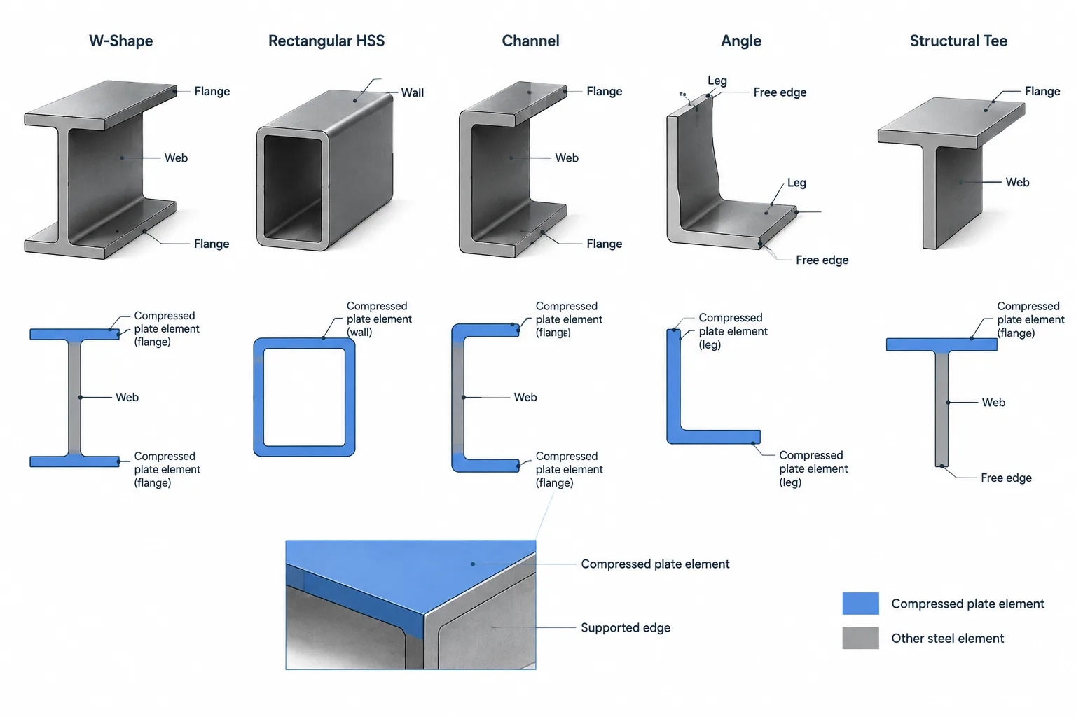
| Section type | Practical Q consideration |
|---|---|
| W-shape or S-shape | Strong-axis shear is commonly evaluated through the web using the flange and partial web area above or below the cut. |
| Structural tee | The neutral axis is not generally at half the overall depth, so centroid location must be established before calculating Q. |
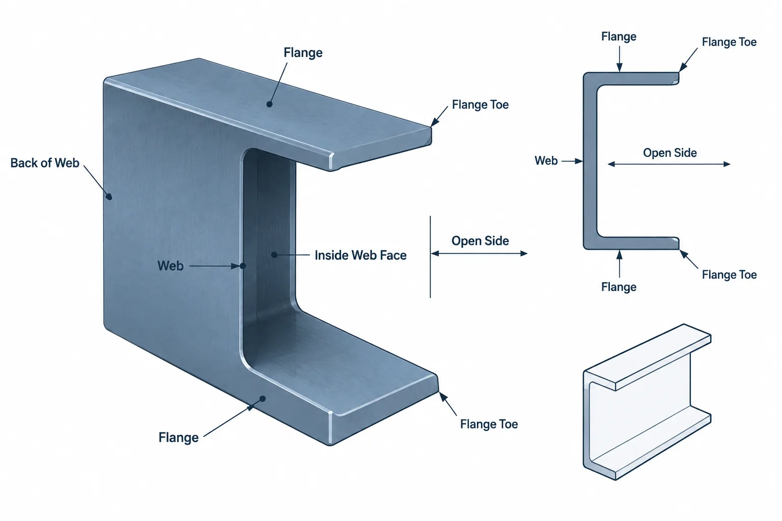
| Channel | Strong-axis Q can be developed from partial areas, but the section’s open, unsymmetric layout also makes shear-center behavior important. |
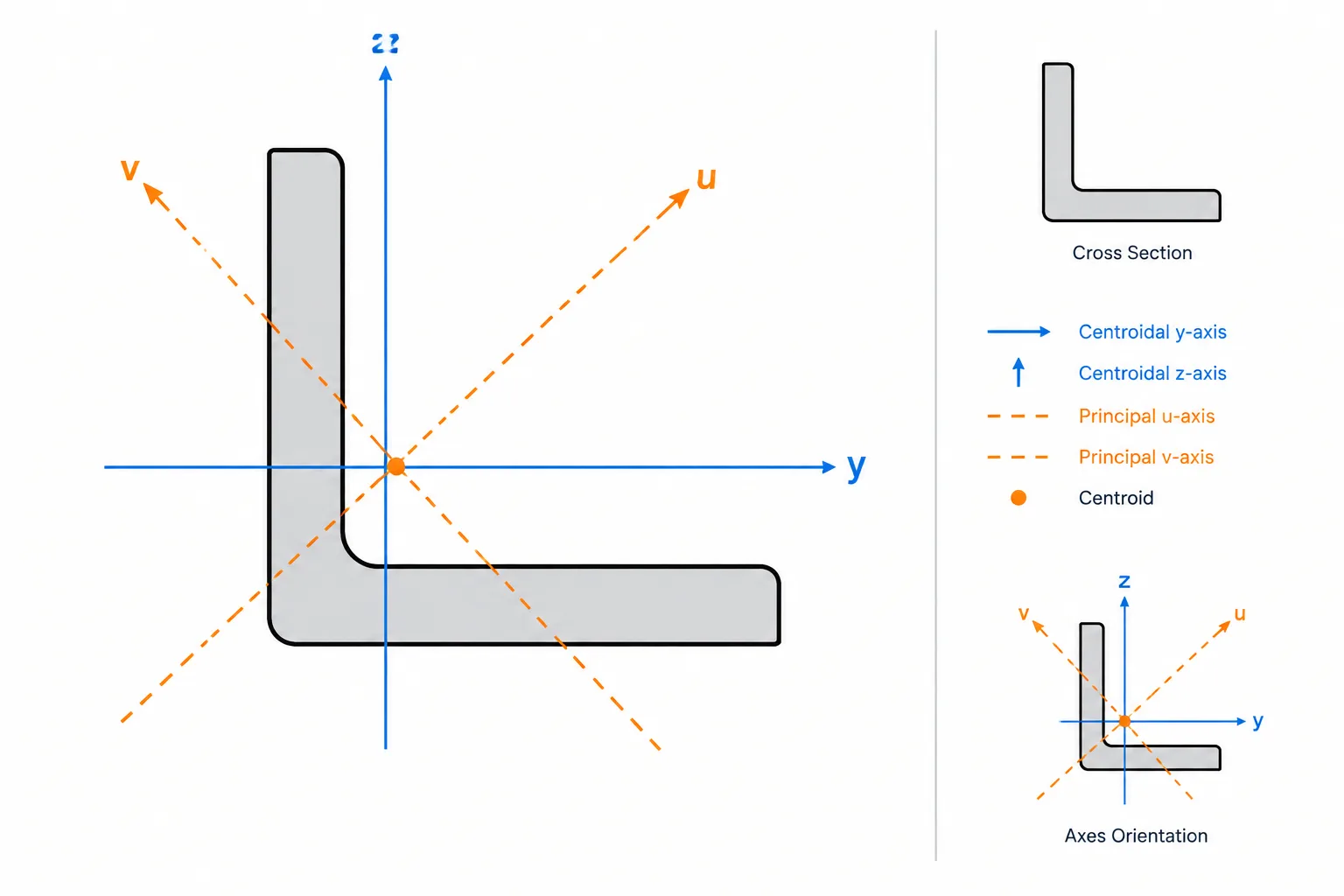
| Angle | Centroidal and principal axes require care. A simple horizontal or vertical cut may not correspond to a principal bending direction. |
| Rectangular HSS | The selected area may cross multiple walls. Closed-section shear flow and torsional behavior should not be reduced automatically to an open-section web calculation. |
| Built-up section | Q can help determine force transfer along interfaces, subject to the assumptions and design procedure used for the assembly. |
Using Q for Built-Up Member Connections
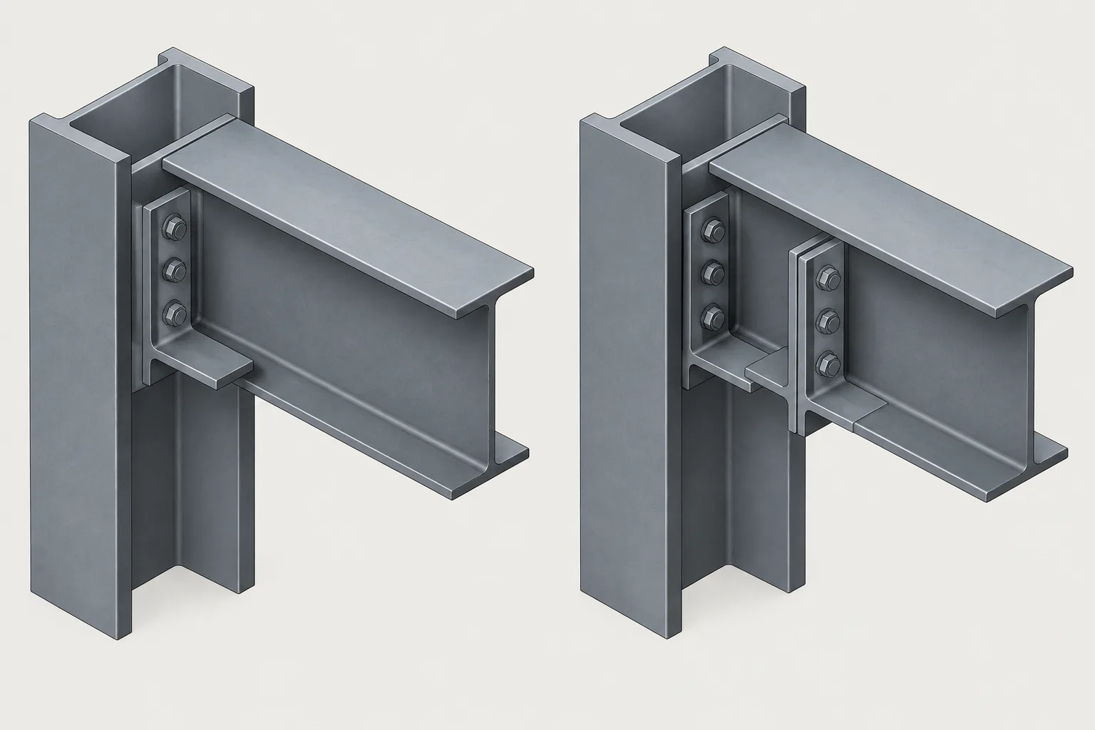
Shear flow is particularly valuable because it expresses force transfer per unit length along an interface. In a built-up member, that interface might be between a web and flange, between a rolled shape and a cover plate, or between multiple components intended to act compositely.
A designer may use the calculated shear flow as part of determining the required transfer through welds, bolts, or other connectors. The connection layout must then account for connector behavior, spacing, load direction, eccentricity, fabrication, and the governing design requirements. Q alone does not establish a complete connection design.
For detailing, clearly identify which components are assumed to act together. A CAD model that shows touching solids does not prove composite action. The force-transfer mechanism must be shown and specified in the project documents.
A Practical CAD Workflow for Calculating Q
- Confirm the section geometry. Use the intended rolled-shape data, plate dimensions, or verified profile. Avoid relying on a visually similar block.
- Establish the complete-section centroid. This defines the neutral axis used for both Q and I.
- Draw the evaluation line. Place it at the exact location where shear stress or interface flow is needed.
- Isolate one side of the cut. Create a closed region representing only the area above, below, or otherwise on the selected side of that line.
- Find the partial area’s centroid. Obtain its area and centroid coordinate using region or mass-property tools.
- Measure to the complete-section axis. The distance must run from the partial-area centroid to the neutral axis of the full section—not to the evaluation line.
- Calculate Q. For one region, multiply its area by the centroid distance. For several regions, sum their individual contributions with a consistent sign convention.
- Check units and axes. Confirm that Q and I use compatible units and refer to the same axis.
When using simplified CAD geometry, document what was omitted, such as rolled fillets or corner curves. If the calculation must agree with published section data, use geometry and properties from a consistent, verified source rather than mixing idealized outlines with tabulated values.
Common First-Moment-of-Area Errors
- Using the whole section: The whole section has a zero first moment about its own centroidal axis when signed distances are used.
- Measuring to the cut: The centroid distance in Q is measured to the full section’s neutral axis.
- Using the wrong I: Q and I must reference the same bending axis.
- Treating Q as constant: Q changes as the evaluation line moves through the section.
- Confusing thickness with flange width: The denominator dimension is the local material width or thickness appropriate to the shear-stress path.
- Ignoring unsymmetric geometry: Channels, angles, tees, and built-up sections may require careful axis selection and shear-center consideration.
- Combining incompatible geometry: Q from an idealized CAD outline should not be paired casually with I from a different section definition.
A Useful Way to Remember Q
Think of Q as a property of a partial area at a specific cut, not as a permanent label for the entire shape. First identify the full-section neutral axis, then select the material on one side of the point being checked. Its area and lever arm define Q.
This distinction makes first moment of area useful beyond textbook shear diagrams. It connects section geometry to web shear, interface force transfer, built-up member behavior, and practical CAD verification—while also showing why careful axis control and consistent geometry matter.