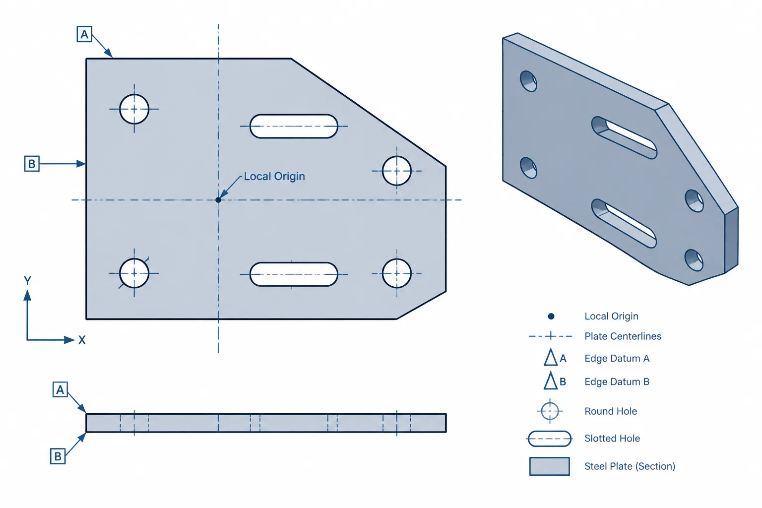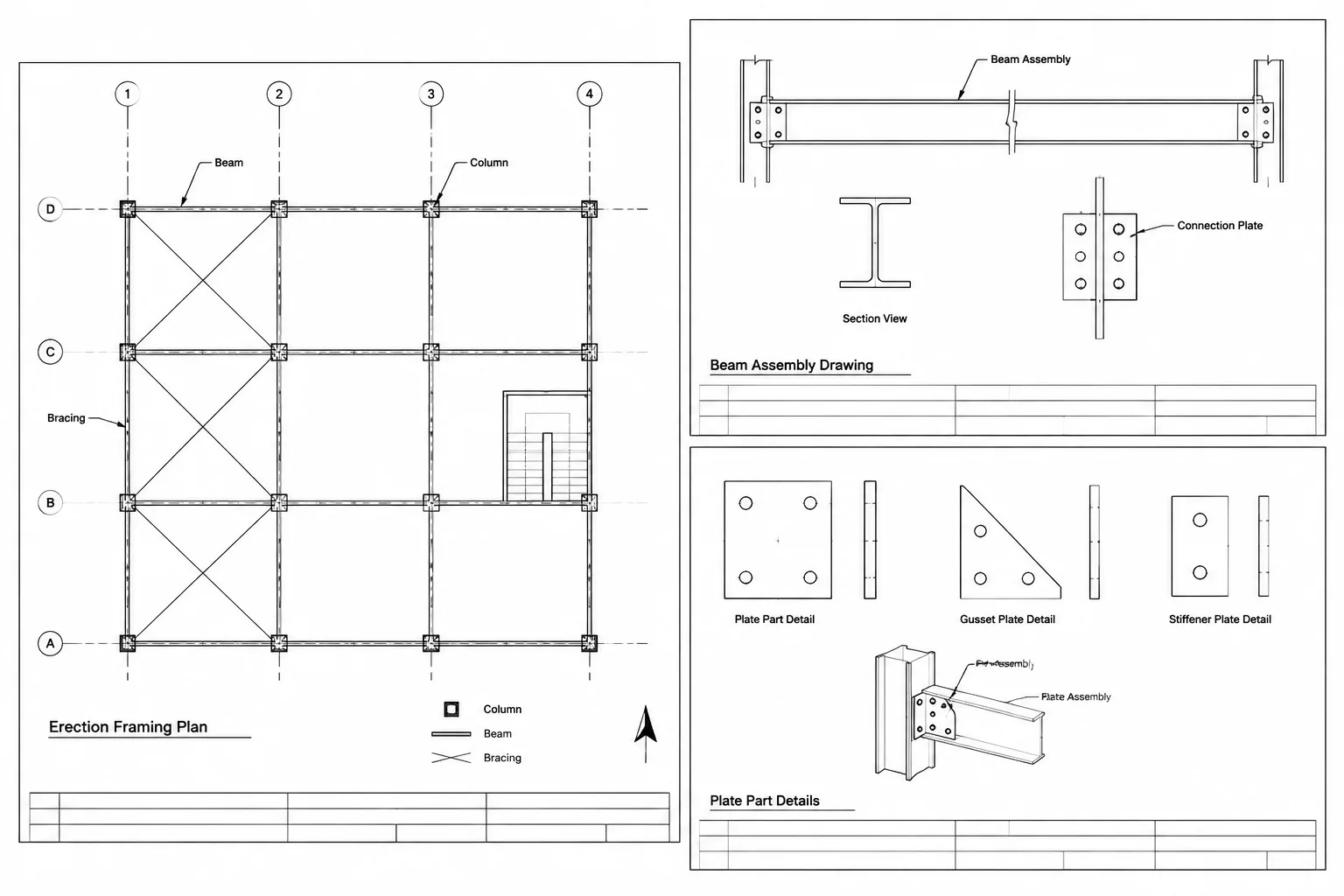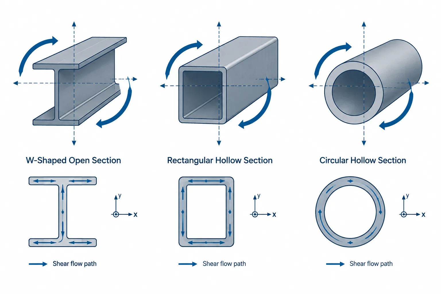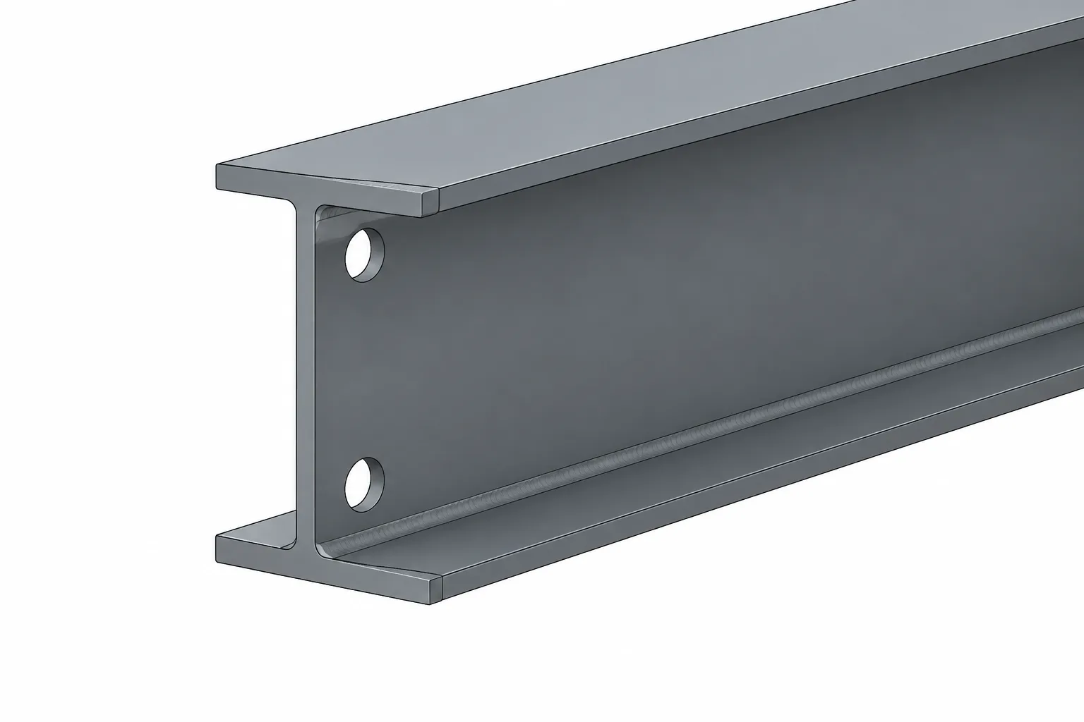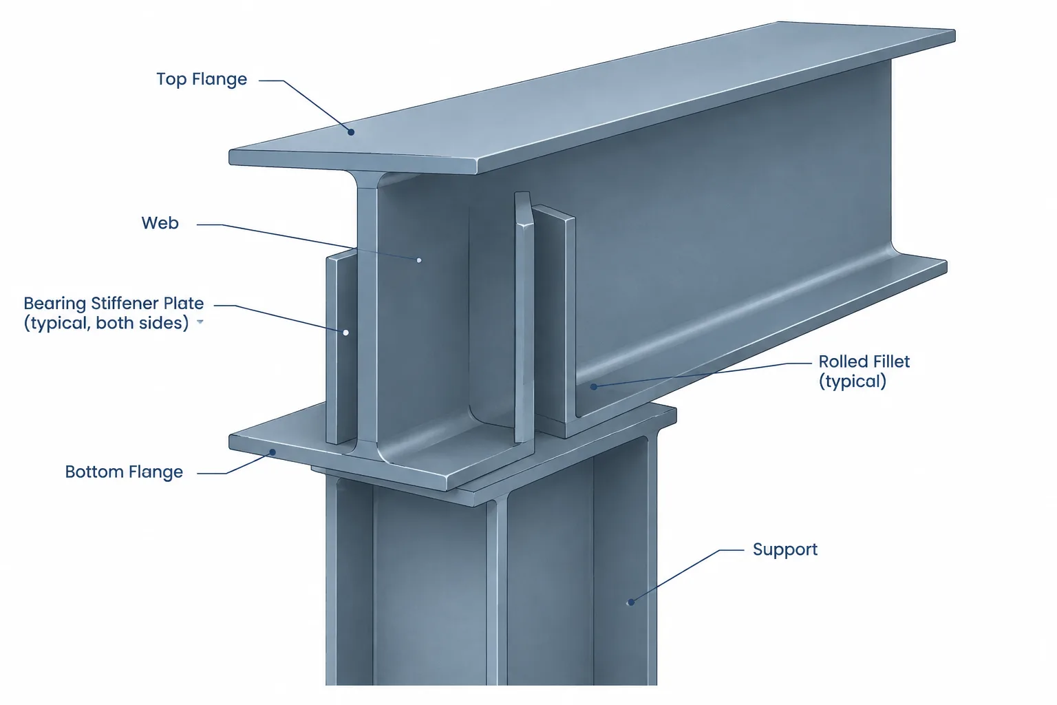
Bearing stiffeners are vertical plates attached to a steel beam web near a support or concentrated load. Although their geometry may look simple, they occupy a crowded region where the beam flanges, web, rolled fillets, connection material, welds, and supporting member all compete for space. A stiffener detail must therefore communicate more than plate width and thickness: it must show where the force enters the beam, how the plates fit around the rolled shape, and which surfaces are intended to transfer load.
The engineer determines whether stiffeners are required and establishes their design forces, sizes, material, welds, and bearing conditions. The detailer’s task is to convert those requirements into fabricable geometry without changing the intended load path. This guide focuses on that coordination process rather than structural capacity calculations.
What a bearing stiffener does
A concentrated reaction or applied load can create high local forces in a beam flange and web. Bearing stiffeners provide a more direct route through this region. They are commonly placed over a support, under a concentrated load, or at another location identified by the connection design.
It is useful to visualize the stiffener and adjacent beam components as a short load-transfer assembly:
- The force enters through a flange, connection element, or bearing surface.
- The stiffener plates and beam web carry the force through the beam depth.
- The force leaves through the opposite flange or another defined connection surface.
This model helps explain why plate position and end fit matter. A stiffener that is offset from the actual reaction line may not represent the intended force path. Likewise, a plate end detailed with a gap cannot be assumed to provide direct bearing unless the design specifically accounts for how the force crosses that gap.
Bearing stiffeners versus general web stiffeners
Not every vertical plate on a beam web has the same function. Some plates reinforce a web panel, stabilize a web region, support a connection, or provide local attachment material. A bearing stiffener is specifically associated with transferring or distributing concentrated force near a defined location.
The drawing should identify the plate’s function through its placement, notes, sections, and relationship to the reaction or load. Using a generic “stiffener” label without showing the controlling load location can leave the shop uncertain about whether the plate must align with a support, seat, column flange, bearing plate, or connection centerline.
| Detailing question | Why it matters |
|---|---|
| What force or reaction is associated with the plate? | Establishes the controlling location and intended load path. |
| Is the stiffener fitted to one flange, both flanges, or neither? | Affects plate length, end preparation, bearing behavior, and weld access. |
| Is the layout paired or one-sided? | Affects web eccentricity, access, and connection interference. |
| What is the plate datum? | Prevents ambiguity between plate centerline, face, and edge dimensions. |
| Which welds are required? | Controls fabrication sequence, access, and load transfer. |
Start with the reaction or load line
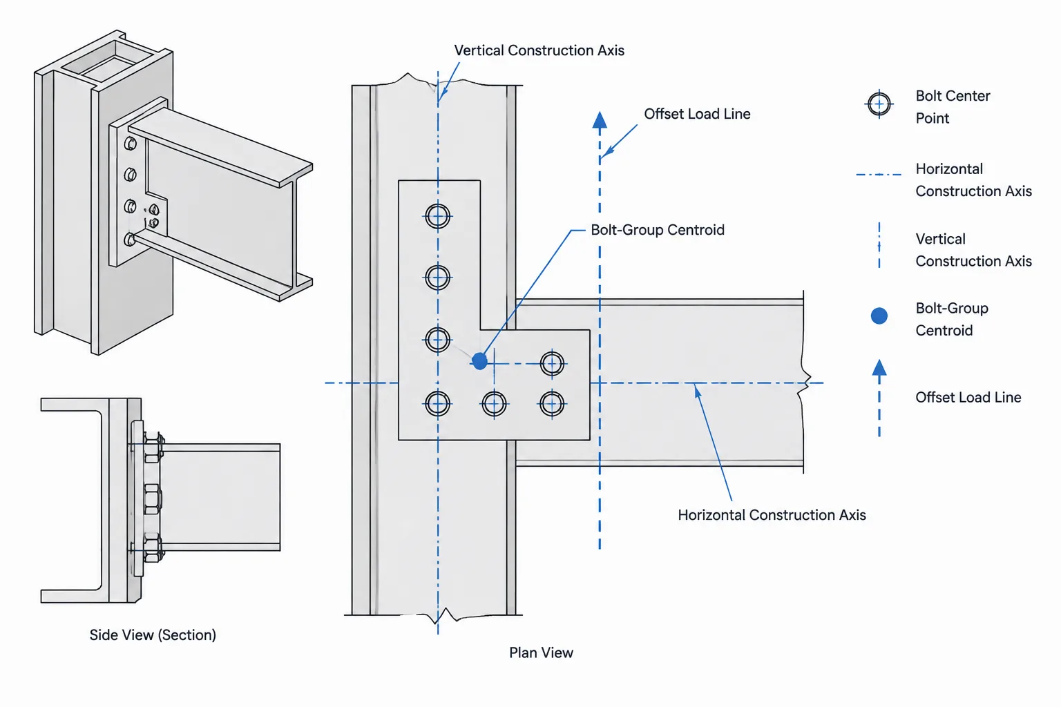
The support location should be established before the plate edges are dimensioned. Depending on the project, the controlling datum may be a column centerline, grid line, bearing centerline, end of beam, face of support, or connection work point.
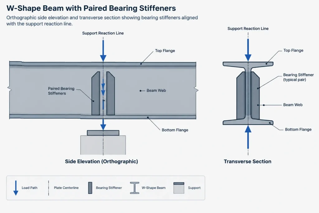
Once that datum is known, the stiffener can be located by its centerline or by a clearly identified plate face. Centerline dimensioning is often useful for a stiffener intended to align with a reaction line. Face dimensioning may be more appropriate where one plate surface must align with another connection component. Either approach can work, but the drawing should not mix them without making the relationship explicit.
Do not assume that the geometric center of a supporting member is automatically the force line. Seats, brackets, cap plates, offset columns, skewed framing, and one-sided connections can move the effective reaction location. Confirm the design intent before centering the stiffener on convenient model geometry.
Paired stiffeners and one-sided plates
Bearing stiffeners are often shown as a pair, with one plate on each side of the web. A paired arrangement can create a more balanced geometry around the web, but it also introduces coordination issues. The two plates may encounter different obstructions, especially when connection angles, shear plates, bolts, diaphragms, or intersecting framing occur on only one side.
A one-sided stiffener should not be substituted for a pair merely to solve a clash. Conversely, an extra plate should not be added to make a drawing appear symmetrical. Plate count and arrangement are design decisions because they influence stiffness, weld distribution, and the way force enters the web.
For paired plates, sections should show whether the plates align exactly through the web or are intentionally offset. If they share a common centerline, dimension that centerline once and use a section to establish the two-sided arrangement. This is generally clearer than repeating independent dimensions that could conflict after a revision.
Fit at the beam flanges
One of the most important drawing distinctions is whether a stiffener plate is fitted to a flange. In shop language, “fit” can imply an intentional contact condition, not simply a plate cut approximately to the clear web depth. The project documents should define the required condition and the detail should represent it consistently.
Fitted to both flanges
A plate extending between the flanges may be intended to contact both flange surfaces. This condition demands careful control of plate length, end preparation, beam geometry, and fabrication sequence. The detail must also account for the rolled fillets where the web meets the flanges; a square plate corner cannot occupy the same space as the fillet.
Fitted to one flange
In some details, the stiffener is fitted at the loaded or bearing flange while the opposite end is cut short or otherwise detailed. The drawing should identify which end carries the fit requirement. A section or enlarged elevation is usually more reliable than a general note that does not distinguish top from bottom.
Not fitted for direct bearing
A plate may terminate with clearance from a flange and transfer force through specified welds or another designed mechanism. The visible gap should not be casually removed during detailing. Closing it changes the physical condition and may introduce unintended contact, fit-up difficulty, or weld restrictions.
Rolled fillets, corner clips, and plate width
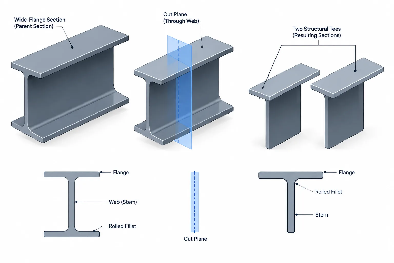
The inside corners of a rolled W-shape are not sharp. The transition between the web and flange occupies part of the nominal rectangular space beside the web. A stiffener plate extending toward a flange therefore needs compatible corner geometry.
Common geometric treatments include clipped corners, shaped reliefs, or other preparations defined by the project detail. The selected geometry must clear the rolled fillet while preserving the required plate engagement and weld access. A generic sharp-corner rectangle copied into the model can conceal a physical clash, especially when simplified beam geometry omits the true fillet region.
Published shape information can help establish the protected fillet zone, but the detailer should use the dimensional conventions appropriate to the selected shape and project documents. Do not derive shop-critical clearance from a visually scaled section symbol.
Plate width also deserves attention. A wider plate may provide more room for welds or load distribution, but it can interfere with flange bolts, connection plates, deck attachments, or adjacent members. Plate width is not merely a drafting preference; changes should be referred to the responsible designer.
Weld access and sequencing
A weld symbol alone does not prove that the weld can be made. Review the stiffener in three dimensions and consider access before and after other pieces are installed. Typical questions include:
- Can the welder reach both sides of the plate-to-web joint?
- Does the flange restrict the electrode, gun, or inspection line of sight?
- Will a nearby end plate, shear plate, or connection angle block access?
- Must the stiffener be installed before another shop attachment?
- Does a corner relief provide enough room without removing required plate material?
- Are weld terminations clear of incompatible intersecting welds?
The fabricator may have preferred sequences and access practices, but those preferences should not be used to revise the engineered weld or bearing condition without approval. When geometry is unusually congested, an enlarged detail and early fabrication review are more useful than relying on a typical detail.
Coordination with common beam connections
At a beam end, bearing stiffeners may overlap the same region used by shear tabs, end plates, seats, clip angles, flange plates, or web bolts. Checking each component separately is not enough; they must be reviewed as a complete assembly.
For bolted work, verify that the stiffener does not block bolt insertion, washer placement, nut rotation, or tightening access. Hidden interference is especially common when a web plate lies on one side and a stiffener lies directly opposite it. Through-bolts may require clear space on both faces even when the visible elevation appears acceptable.
For welded connections, look for intersecting welds, inaccessible returns, and conflicting plate edges. Also check whether the stiffener prevents the beam end from entering a seat or fitting between erection components. A shop-welded plate that is structurally correct can still create an erection problem if it enlarges the effective beam envelope.
What to show on the drawings
A complete stiffener detail normally requires more than a single elevation. The exact drawing set varies, but the following information should be clear:
- Stiffener quantity and whether plates occur on one or both sides of the web.
- Plate mark, material identification, thickness, width, and developed geometry as specified.
- Location from a stable beam, support, or grid datum.
- Relationship between the stiffener and the reaction or concentrated load line.
- Fit or clearance condition at each flange.
- Corner clips or relief geometry needed around rolled fillets.
- Weld extent, side, continuity, and termination based on the design information.
- Conflicts or required clearances involving bolts, plates, seats, and intersecting members.
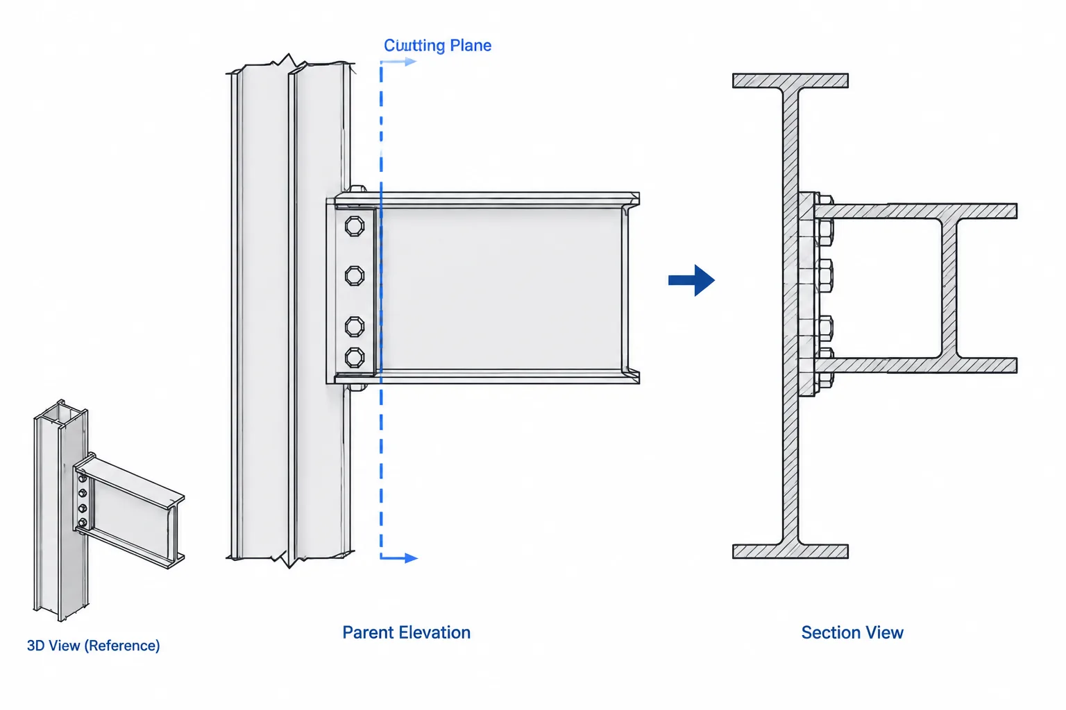
An elevation communicates vertical position and plate length, while a transverse section confirms the one-sided or paired arrangement. A plan or local section may be necessary when the support is skewed or the stiffeners are not normal to the beam web.
CAD and model checks
Use the model to test geometry, but do not let automatic placement replace design interpretation. A stiffener component inserted at the beam midpoint or attached to a generic end plane may not follow the actual reaction line. Confirm the component’s insertion point and dependencies before copying it to other members.
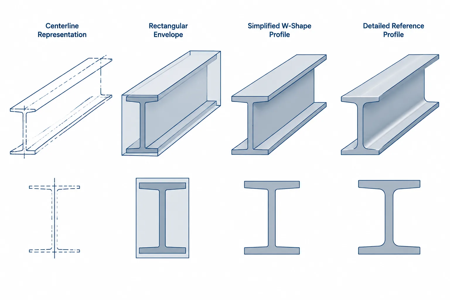
Useful model checks include isolating the beam web, flanges, stiffeners, connection material, bolts, and supporting member; cutting transverse sections through each plate; and reviewing the assembly from both beam ends. If the model uses simplified rolled shapes, perform a separate check for the flange-to-web fillet zone.
Recheck stiffeners after any beam size substitution. Changes in depth, flange thickness, web thickness, and fillet geometry can affect plate length, clips, weld access, and adjacent connection clearances even when the beam work points remain unchanged.
Practical review checklist
- Confirm the design identifies the number, size, material, and purpose of the stiffeners.
- Locate the controlling reaction or concentrated load line.
- Verify whether the plate datum is its centerline, face, or edge.
- Show clearly whether each end is fitted, welded, or held clear.
- Check rolled fillet clearance using appropriate shape geometry.
- Review access for welding, bolting, inspection, and erection.
- Coordinate stiffeners with all connection material on both sides of the web.
- Use sections to confirm paired, offset, or one-sided layouts.
- Recheck geometry after member or connection revisions.
- Refer any change to plate arrangement, fit, or weld requirements to the responsible designer.
Bearing stiffeners are small components with a direct relationship to concentrated force transfer. Clear datums, explicit end conditions, realistic rolled-shape geometry, and assembly-level clash checks turn a generic pair of plates into a detail that can be fabricated and coordinated as intended.