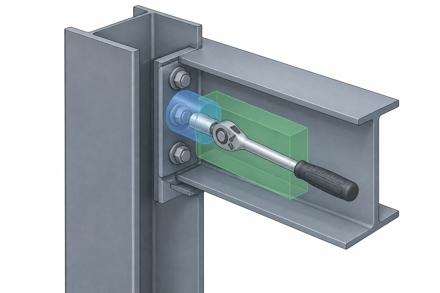
A bolted steel connection is not fully defined by the bolt diameter and layout alone. The holes may be standard round holes, oversized round holes, short slots, or long slots. That distinction affects fit-up, connection behavior, fabrication information, inspection, and the way the connection must be shown on shop and erection drawings.
For drafters and modelers, the central task is not to decide which hole type a connection needs. That decision belongs in the connection design and project requirements. The detailing task is to convert the specified hole type into unambiguous geometry, dimensions, notes, and model data without silently replacing it with a generic circular hole.
The bolt and the hole are different pieces of information
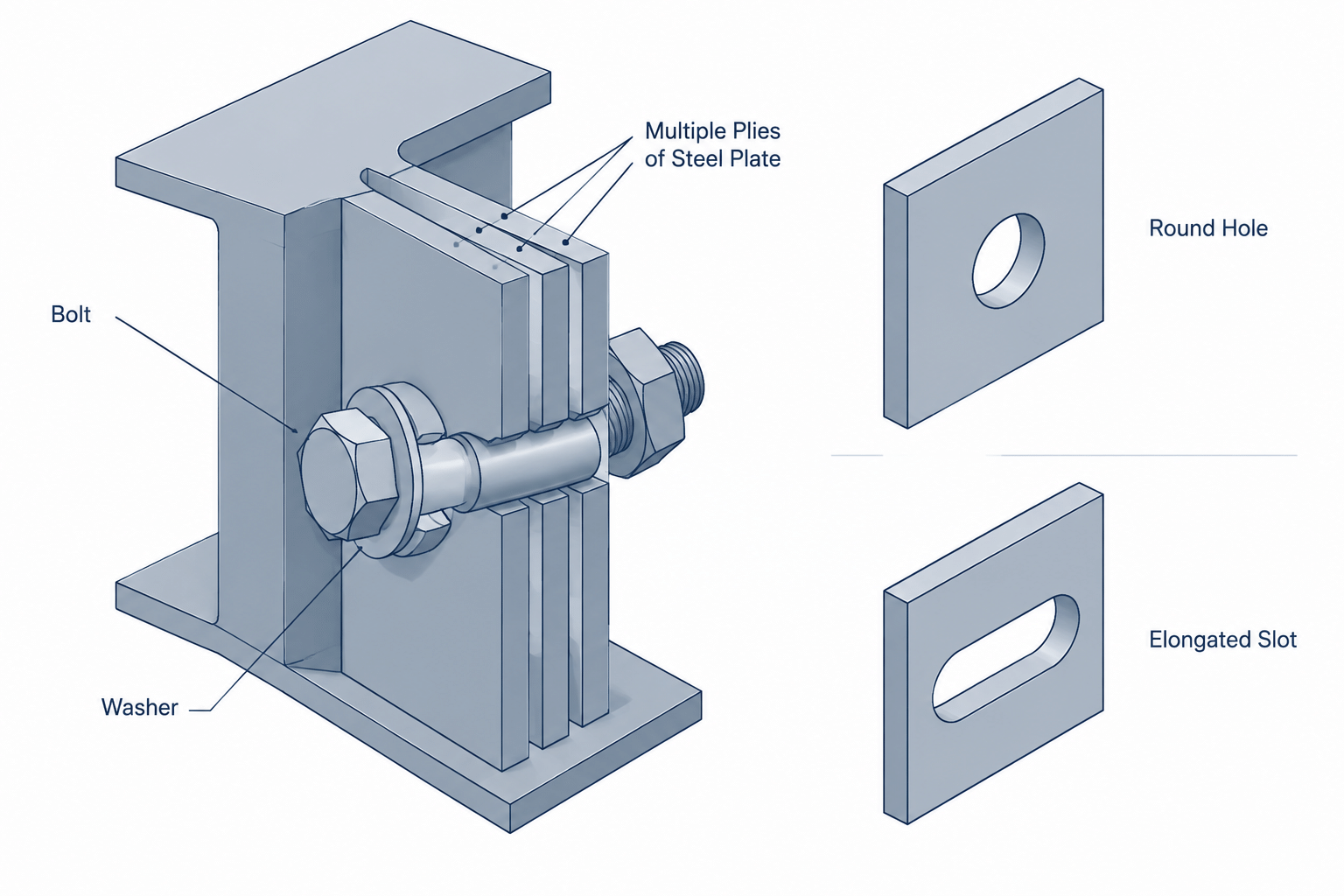
A bolt designation identifies the fastener, but it does not by itself define the opening through the connected material. Structural bolt holes normally provide some clearance around the bolt, and special hole types provide additional clearance in one or more directions.
A complete connection description may therefore need to communicate:
- The bolt diameter and other specified fastener information
- The hole type in each connected ply
- The required hole diameter or slot width and length
- The orientation of any slot
- Which member or plate contains the special hole
- Whether different plies have different hole types
- Any connection-specific requirements supplied by the engineer or project documents
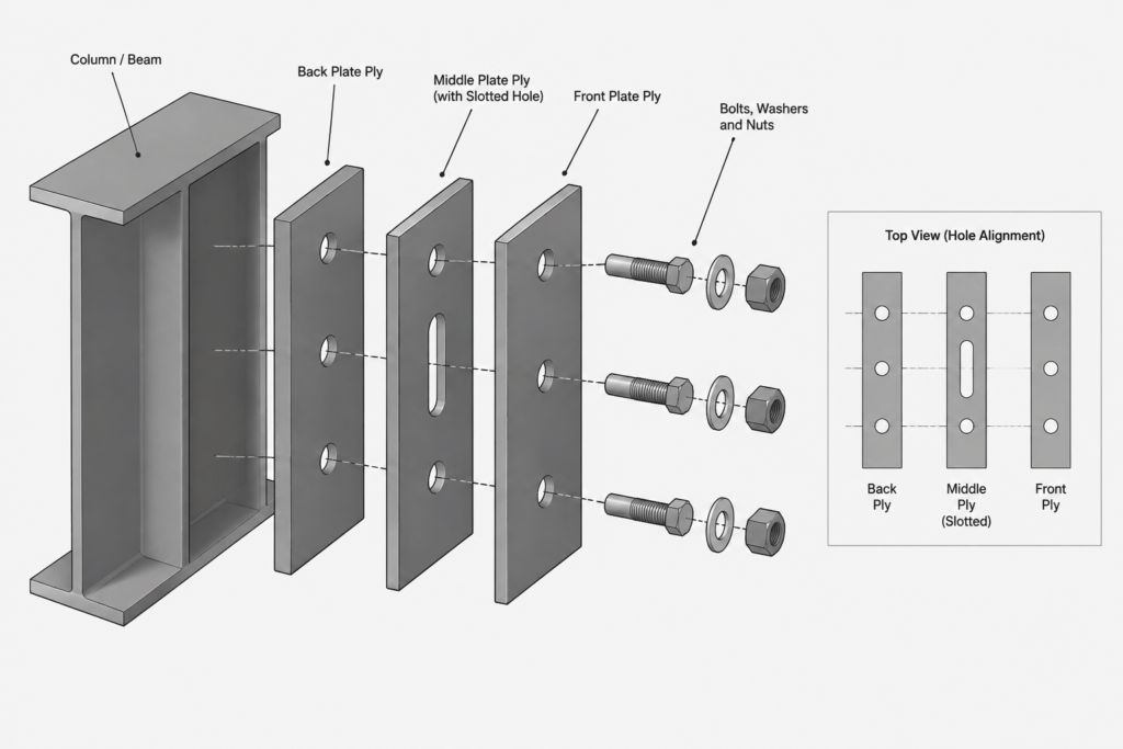
Do not assume that every material layer receives identical holes. A slotted hole might be required in a connection plate while the supported member receives round holes. A plan or section that shows only bolt center marks can conceal this important difference.
Comparing the four common hole categories
| Hole type | Basic geometry | Information that must be clear | Common drafting risk |
|---|---|---|---|
| Standard hole | Round opening with the specified clearance for the bolt | Hole diameter or a verified project designation | Drawing the opening at the bolt diameter |
| Oversized hole | Round opening with more clearance than a standard hole | Actual hole diameter and affected ply | Displaying it as an ordinary round hole with no note |
| Short-slot hole | Elongated opening with semicircular ends | Slot width, overall length, orientation, and affected ply | Rotating the slot or dimensioning only its center |
| Long-slot hole | More elongated opening with semicircular ends | Slot width, overall length, orientation, and affected ply | Using a visually stretched short-slot symbol without verified dimensions |
The names classify the holes, but the labels are not substitutes for verified geometry. The applicable project criteria must supply the required sizes and permitted use. A detailer should not estimate dimensions from a plotted symbol or copy them from an unrelated connection.
Standard round holes
A standard hole is the ordinary round hole used for many structural bolted connections. Although it may look simple, it should still be treated as a defined fabrication feature. The opening should not automatically be modeled at the bolt shank diameter, and a CAD circle should not be scaled by eye to create clearance.
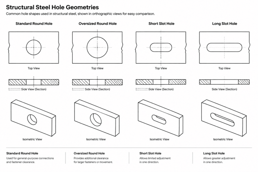
In a detailed model, it is useful to keep the bolt diameter and hole diameter as separate parameters. This allows schedules, templates, CNC data, and checking tools to distinguish the fastener from the fabricated opening.
Oversized round holes
An oversized hole remains circular but provides greater clearance. Because it can look similar to a standard hole at common drawing scales, graphics alone may not communicate the difference. A note, callout, hole table, or other established project convention should identify it.
The drawing must also indicate where the oversized hole occurs. A single bolt passing through several plies does not mean that all those plies necessarily have the same opening. Sections and assembly views are often more effective than plan views for showing which plate or member contains the special hole.
Short-slot holes
A short slot provides additional clearance along one axis. Its geometry is typically represented by two parallel sides connected by rounded ends. The critical drafting issue is direction: the same slot rotated ninety degrees is not the same connection detail.
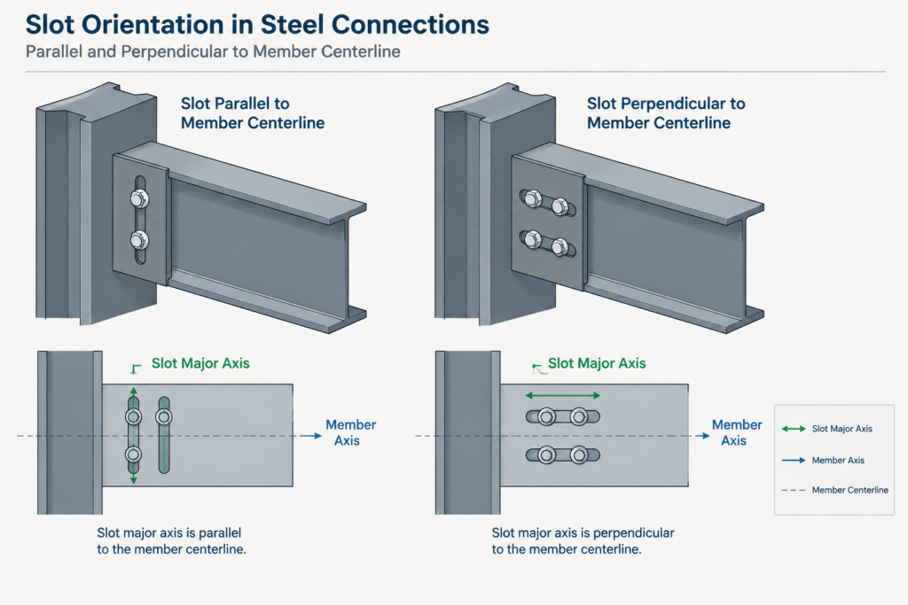
A slot may be described as horizontal or vertical in a particular view, but such wording can become ambiguous when a member is sloped, rotated, or viewed from the opposite side. Where practical, define the slot relative to stable geometry, such as parallel or perpendicular to the member axis, plate edge, bolt line, or another clearly identified reference.
Long-slot holes
A long slot uses the same general geometric concept but permits substantially more movement or adjustment along its major axis. It should never be created by taking a generic slot block and stretching it until it appears appropriate. Width, overall length, end radii, center position, and orientation must remain controlled.
Because a long slot may relate to erection adjustment, movement, or another connection-specific purpose, nearby notes and details should be reviewed together. The appearance of a slot does not establish why it is present or how the connection is intended to behave.
Slot orientation must have a reference
The phrase “slot direction” can refer to the slot’s long axis, while connection documents may discuss loads or movement relative to that axis. Drafters should avoid interpreting design intent from appearance. Instead, reproduce the specified orientation and identify it with geometry that survives view changes.
Useful orientation references include:
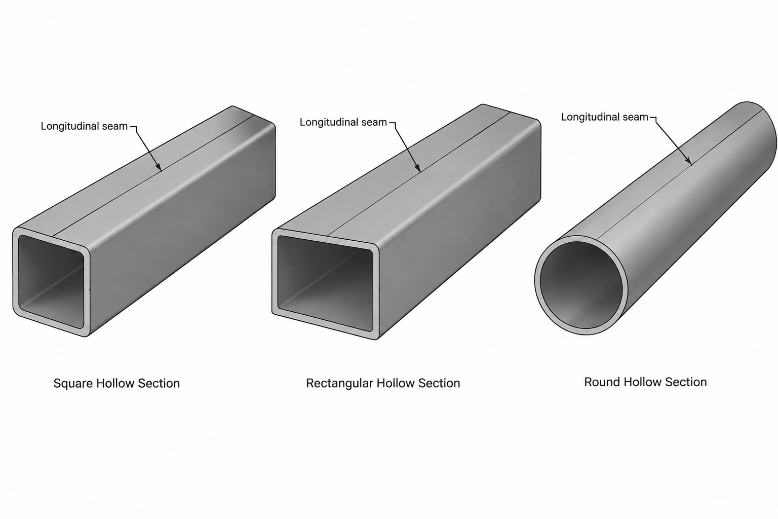
- Parallel to the longitudinal axis of a beam, brace, column, or HSS member
- Perpendicular to a defined bolt line
- Parallel to a plate edge that is itself dimensioned
- Aligned with a slope or radial work line
- Located by coordinates in a fabrication model
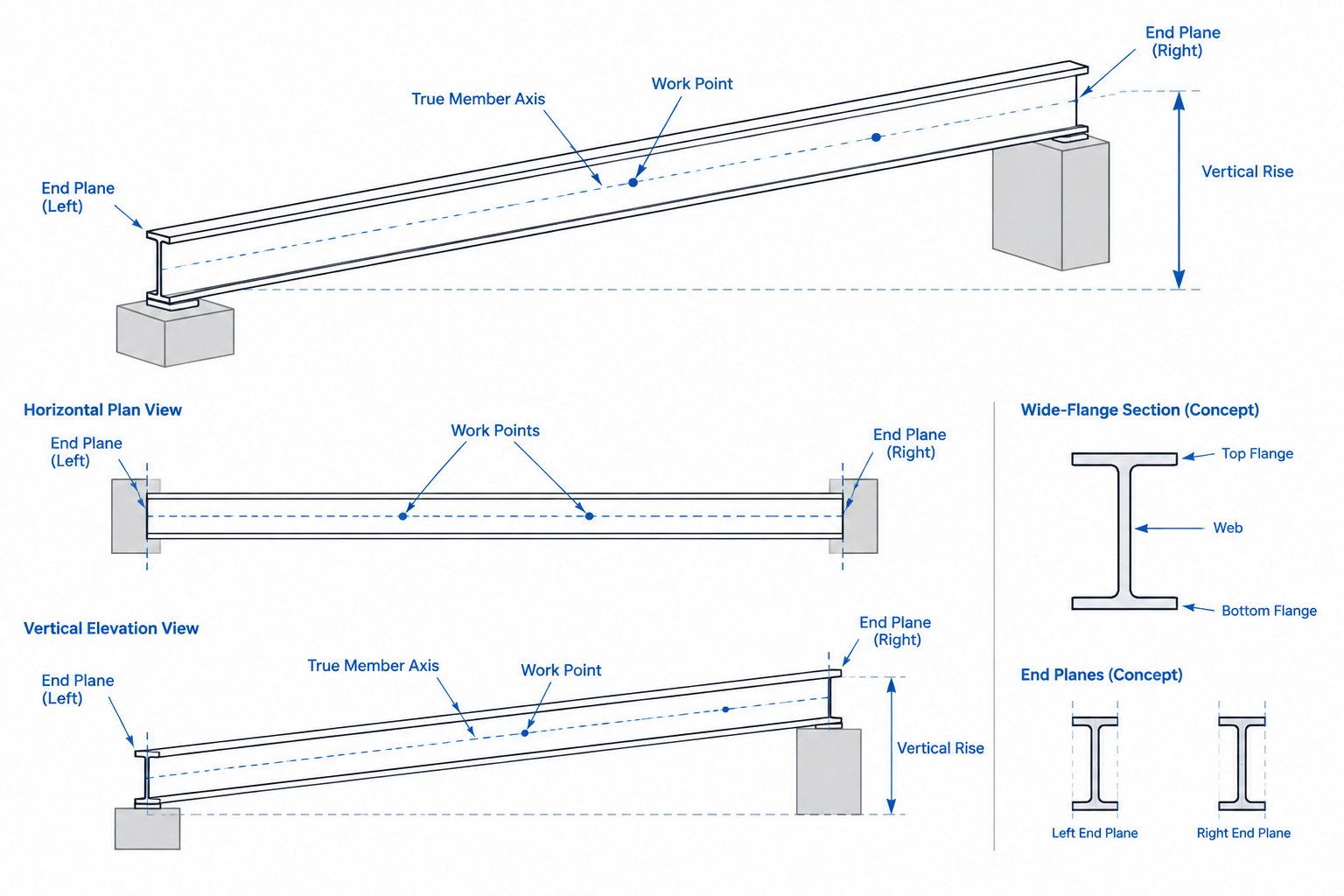
On skewed or sloping members, a slot shown horizontally on the sheet may not be horizontal in the member’s local coordinate system. Model and drawing checks should therefore compare the slot against the member or plate, not only against the page.
Dimensioning round holes and slots
Bolt layouts are commonly located from hole or bolt centers using gage, pitch, edge distance, and end distance. Those center-based dimensions establish the pattern, but special holes require additional information. A slot needs both its location and its shape.
A practical slot callout or hole table should communicate:
- Slot width
- Overall slot length
- Major-axis orientation
- Quantity
- Material piece or ply receiving the slot
- Center location within the bolt pattern
Do not confuse a center-to-edge dimension with the remaining clear steel between the edge of the opening and the edge of the part. They describe different geometry. This distinction becomes particularly visible when a slot points toward a plate end. Connection checks must use the definitions and criteria applicable to the project rather than a measurement inferred from the drawing.
CAD and modeling workflow
A reliable CAD workflow treats hole geometry as data rather than decoration. A useful sequence is:
- Read the connection information. Identify the bolt size, hole type, affected plies, and slot orientation before placing geometry.
- Establish the bolt pattern. Locate centers from controlled work lines, member axes, plate edges, gages, and pitches.
- Apply the correct opening to each ply. Do not assume one hole definition propagates correctly through the assembly.
- Verify local orientation. Check slots against the member or plate coordinate system, especially for sloped, skewed, mirrored, or rotated parts.
- Add drawing communication. Use callouts, hole tables, sections, or detail views appropriate to the office standard and project requirements.
- Review fabrication output. Confirm that exported hole data preserves the intended type, size, and orientation.
Blocks and parametric components can reduce repetitive drafting, but their default values require verification. Mirroring is a particular concern: a mirrored connection may look correct while a slot reference, plate side, or affected ply remains assigned incorrectly.
Drawing checks that catch common errors
Before releasing a shop or erection drawing, check more than the number of bolt symbols. A focused review should ask:
- Does every special hole have a stated or scheduled size?
- Is each slot’s long-axis direction unmistakable?
- Is it clear which plate or member contains the special hole?
- Do plan, elevation, section, and model views agree?
- Are hole centers located independently from hole outlines?
- Were slot shapes preserved after rotating or mirroring the connection?
- Do edge and end conditions reflect the actual opening geometry?
- Are bolt symbols, hole graphics, notes, and fabrication data consistent?
Visual conventions differ among fabricators and detailing systems, so a particular symbol should not be assumed to have universal meaning. When the geometry matters, direct dimensions and explicit notes are safer than relying on line style or appearance alone.
Keep design selection separate from detailing execution
Oversized and slotted holes can affect connection behavior and may be subject to restrictions involving load direction, faying surfaces, washers, installation, and other design or fabrication considerations. Those requirements should come from the connection design, governing project documents, and applicable standards.
The detailer’s responsibility is to identify missing or conflicting information, request clarification when necessary, and accurately communicate the resolved condition. Replacing an unspecified hole with a convenient CAD default can change more than the drawing—it can change how the connection fits and performs.
The best bolted-connection drawings make three things immediately clear: where the bolt centers are, what opening exists in each ply, and how any slot is oriented. Keeping those items separate and explicit improves coordination from engineering through fabrication and erection.