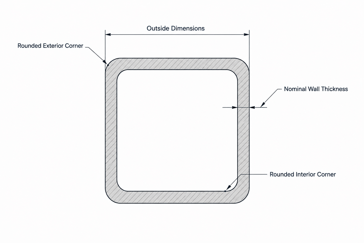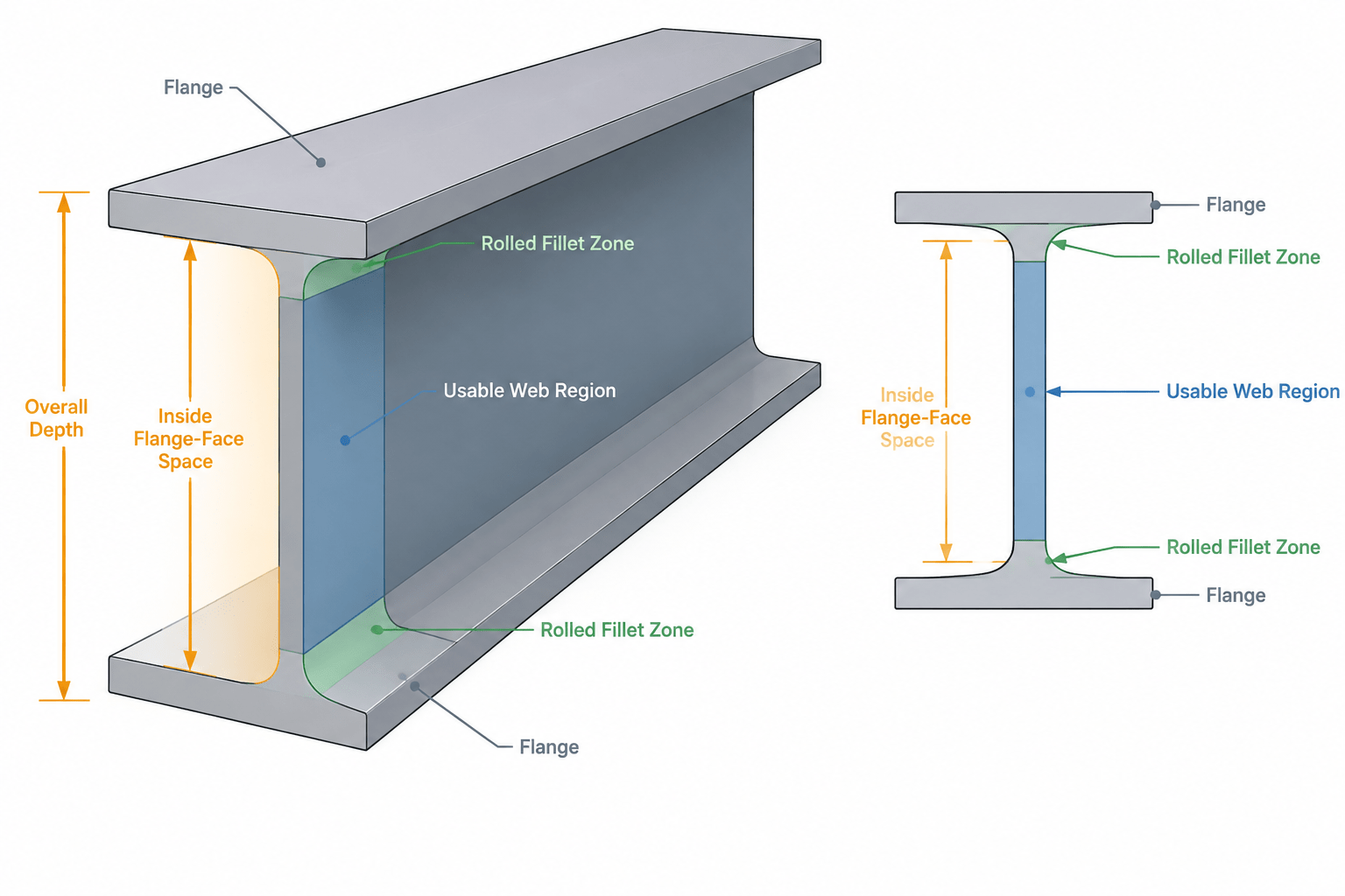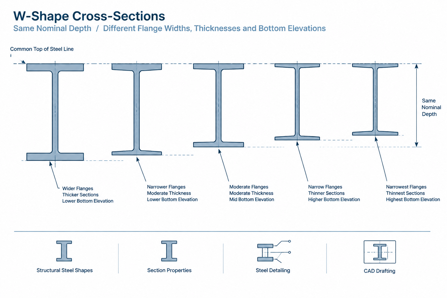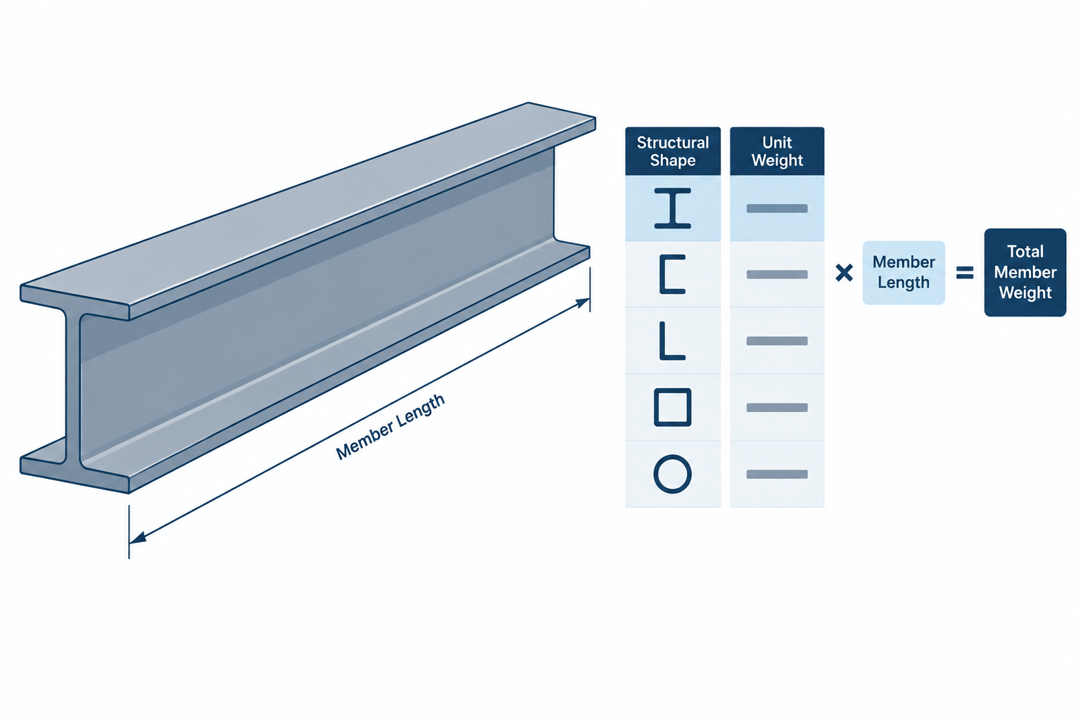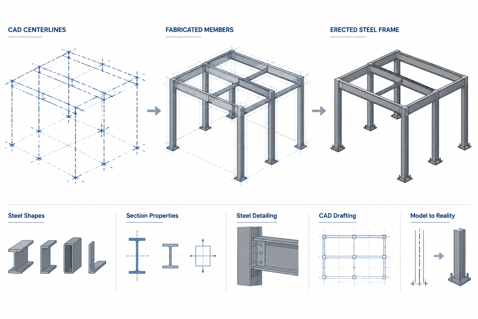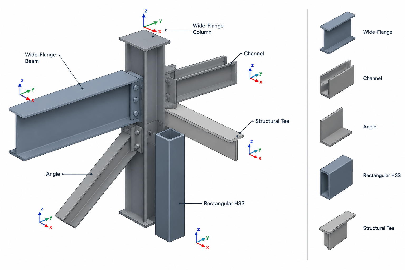
Hollow structural sections are commonly identified by their outside dimensions and nominal wall thickness. That information is appropriate for shape identification, but it does not fully define the usable opening inside the member. This distinction matters when a connection includes an insert plate, internal sleeve, plug, diaphragm, knife plate, or another component that must pass through or fit within the HSS.
A quick subtraction of two wall thicknesses may provide a rough estimate between opposing flat walls. It does not capture rounded corners, wall-thickness variation, manufacturing tolerances, internal weld conditions, or member distortion. For fit-critical detailing, published section data should therefore be treated as reference information rather than a guaranteed description of the internal cavity.
HSS designations primarily describe the outside envelope
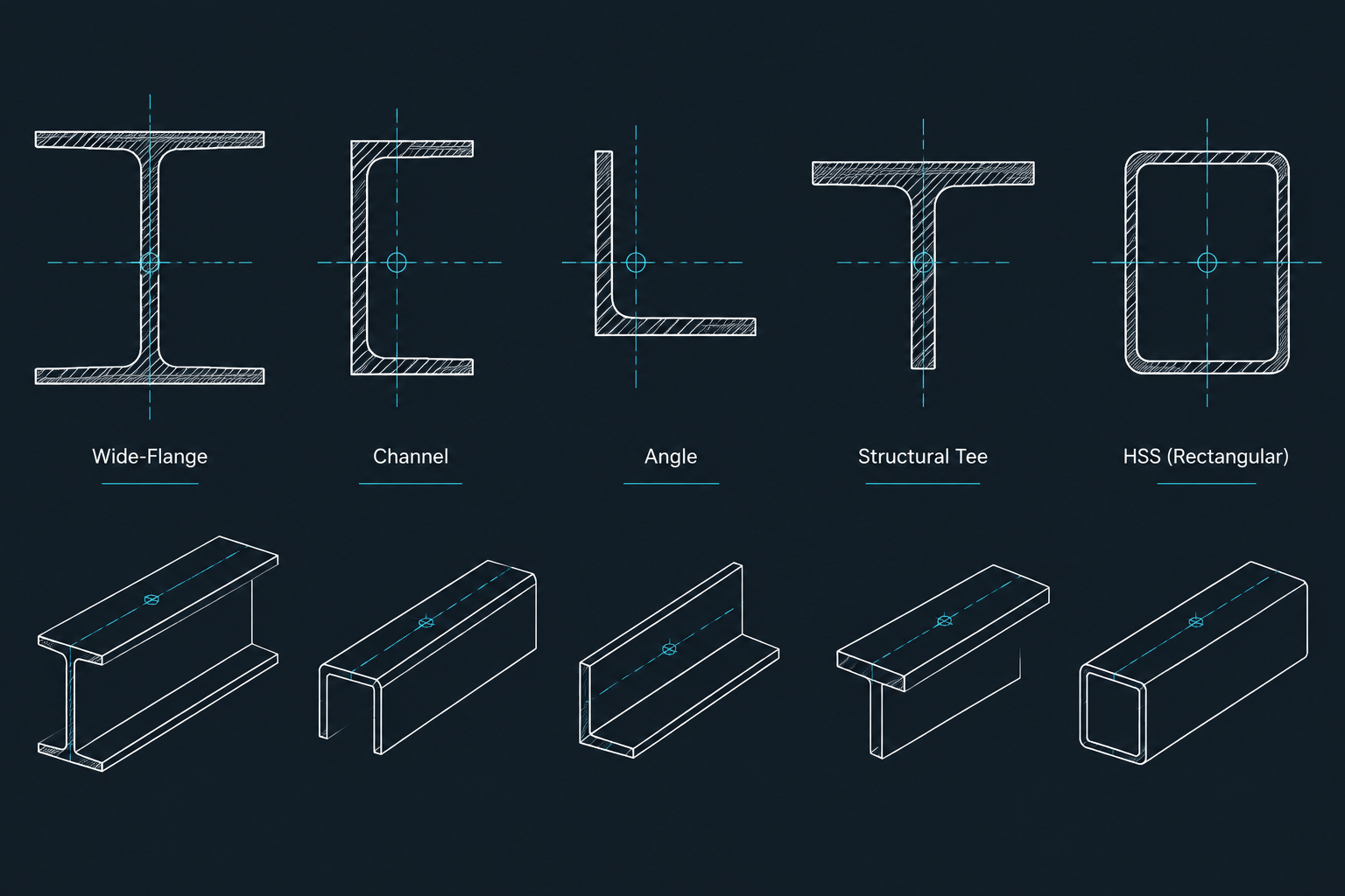
Square and rectangular HSS designations communicate nominal outside dimensions followed by nominal wall thickness. Round HSS designations similarly use an outside diameter and wall thickness. Unlike some mechanical tubing products selected specifically for a controlled bore, structural HSS is generally referenced by its exterior envelope.
This outside-based convention is useful for structural layouts. The exterior faces establish member depth, width, clearance to adjacent construction, and the location of plates welded to the section. It is less useful when a fabricator needs to know whether a rigid object will slide into the member.
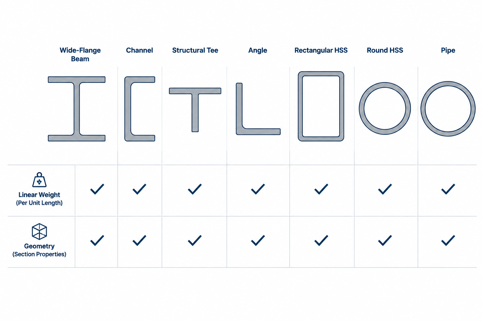
Shape tables may list dimensions and section properties needed for design and drafting, but an inside width or corner-to-corner opening is not usually the defining size of an HSS. Even if an internal dimension is calculated from table values, it should not automatically be interpreted as a minimum available clearance.
Why outside size minus two walls is only an approximation
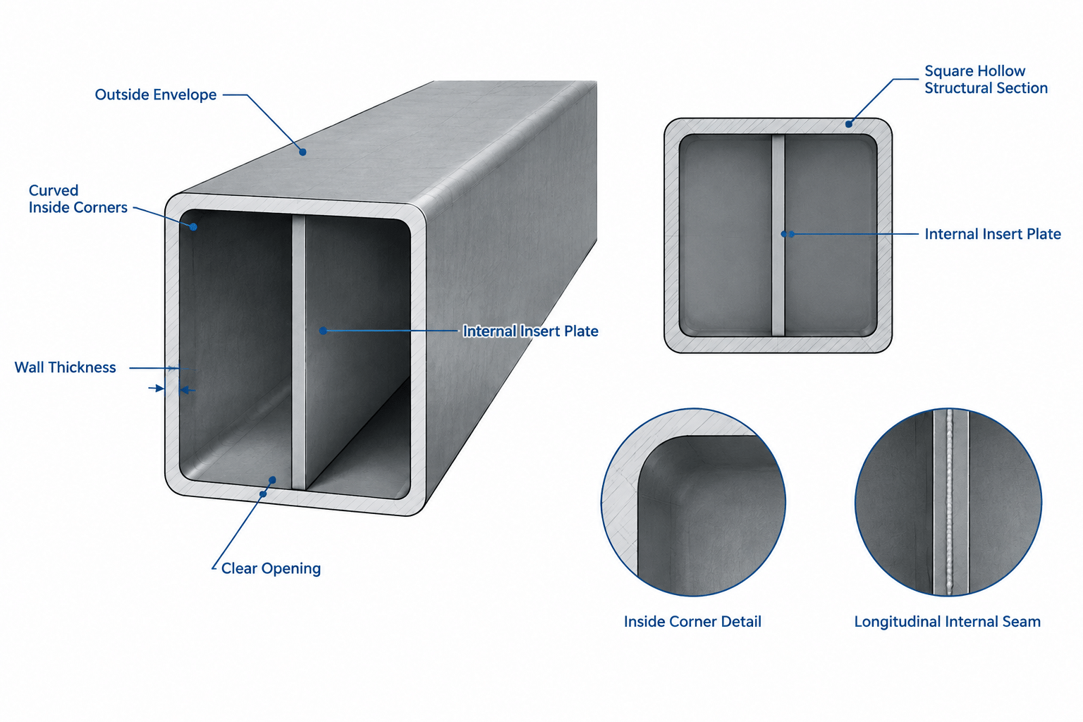
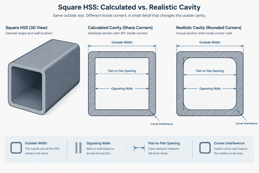
For a flat region of square or rectangular HSS, a conceptual inside distance can be written as the outside distance minus the thickness of the two opposing walls. This is useful for preliminary geometry, but several conditions limit its accuracy:
- Nominal and actual wall thickness are not identical concepts. A designation describes a nominal wall, while the delivered product has permitted manufacturing variation.
- Design thickness serves a calculation purpose. A reduced thickness value used in structural calculations is not a measurement of the physical cavity and should not be used as though it defines fabrication clearance.
- The walls meet through curved corners. An insert approaching a corner encounters the inside radius before it reaches the theoretical intersection of two flat wall surfaces.
- The section may not be geometrically perfect. Normal manufacturing variation can affect squareness, straightness, flatness, and the relationship between opposing surfaces.
- A longitudinal seam may affect local clearance. Depending on the product and manufacturing process, the internal seam condition may differ from an ideal smooth wall.
As a result, a calculated flat-to-flat opening can be helpful for coordination but insufficient for releasing a close-fitting insert for fabrication.
Inside corners control many rectangular HSS inserts
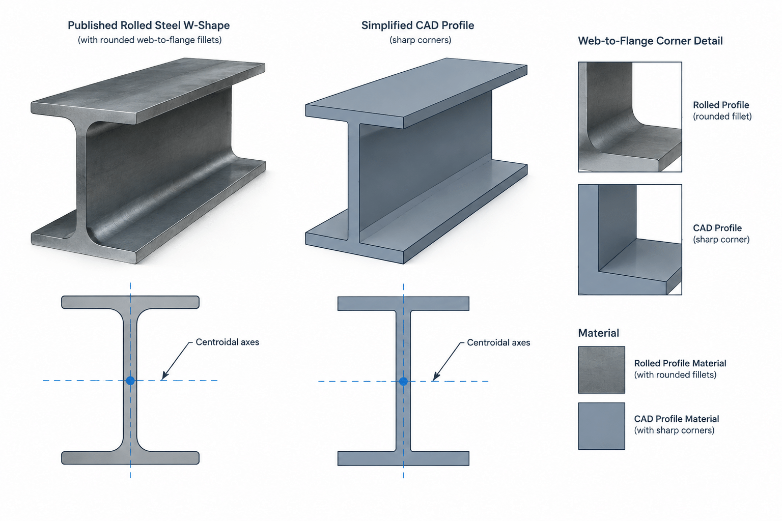
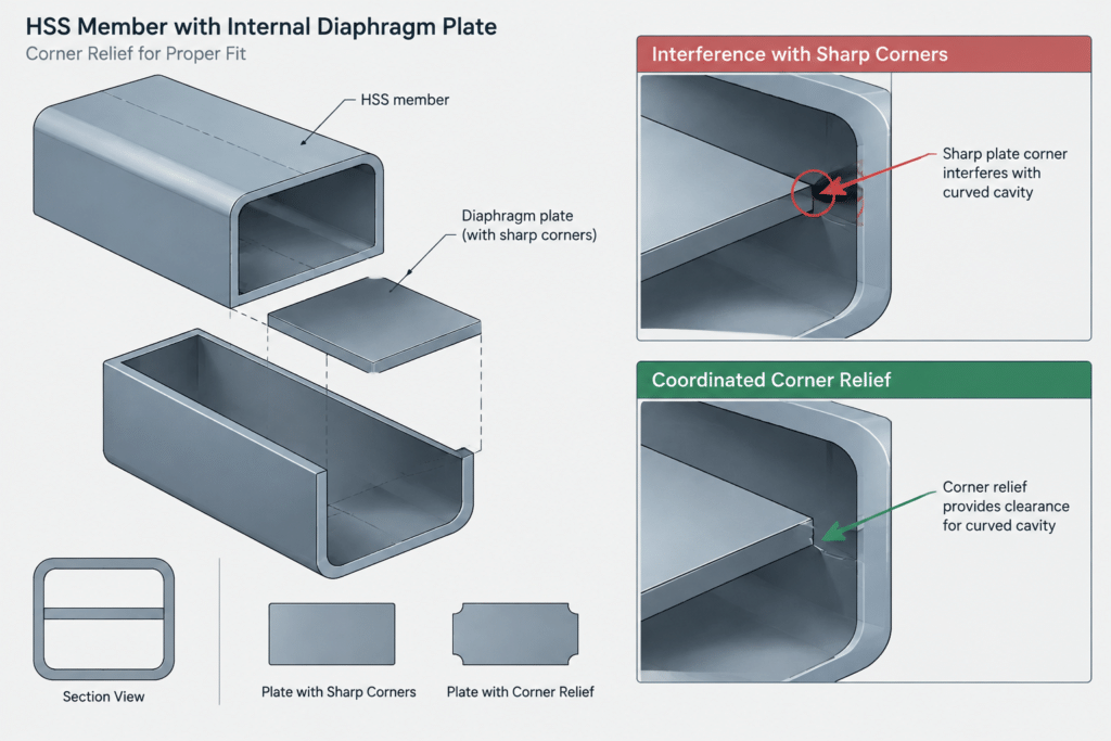
The outside corners of square and rectangular HSS are rounded, and the inside corners are also curved. These curves substantially affect the shape of the clear opening. A rectangular plate with sharp corners may fit between the flat walls in theory yet interfere with the inside corner radii during insertion.
This is especially important for plates oriented across the HSS cavity. The controlling geometry is often not the nominal flat-to-flat distance but the combination of the available flat width and the corner transition. Common detailing responses include clipping the plate corners, rounding them, using a narrower plate, or dividing an internal component into pieces that can be assembled differently.
Corner modifications should not be improvised solely to make a CAD model look clear. Their size and configuration can affect load transfer, weld access, bearing, and the intended connection behavior. The connection designer must establish the required geometry, while the detailer must represent it clearly enough for fabrication.
Flat-to-flat clearance is not corner clearance
Two separate checks are useful when reviewing an insert:
- Flat-wall check: Does the component clear the opposing inside wall surfaces, allowing for realistic variation and the required installation gap?
- Corner check: Does the component avoid the curved inside corners throughout insertion and in its final position?
A plate can pass one check and fail the other. CAD interference checks are useful only when the model includes a realistic internal profile rather than an idealized hollow rectangle with sharp corners.
Internal seams and local obstructions
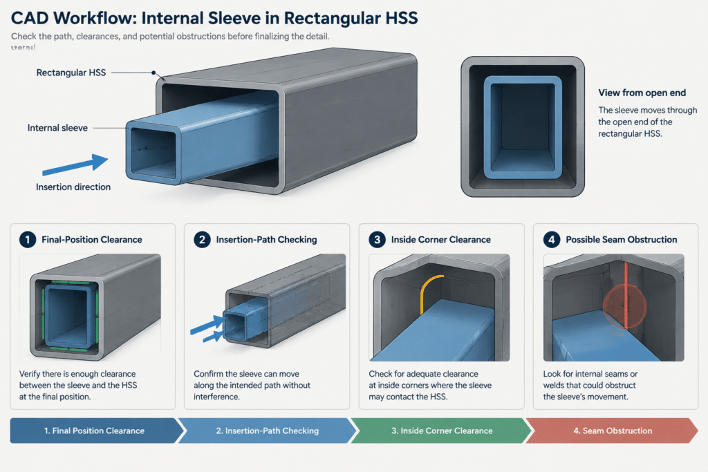
HSS production involves forming and welding a longitudinal seam. The condition visible on the interior depends on the section and production process. A detailer should not assume that every member has a perfectly flush internal surface or that the seam will occur on a particular face unless that condition has been verified.
Internal seam conditions can matter for long sleeves, fitted diaphragms, end plugs, and components intended to slide through a substantial member length. A part that clears the general cavity may still catch on a local projection or encounter resistance where the member is slightly distorted.
Orientation can also matter. If a connection requires the seam to avoid a specific face or internal component, that requirement needs to be coordinated with the fabricator and purchasing team. A seam position inferred from a generic CAD block should not become an undocumented fabrication requirement.
Common connection details affected by the clear opening
| Detail type | Potential fit issue | Useful coordination question |
|---|---|---|
| Internal sleeve | Wall variation, corners, seam condition, and accumulated friction over the sleeve length | Is the sleeve intended to slide freely, be driven, or be shop-fitted? |
| Through-plate or knife plate | Slot alignment, inside corner interference, and access for welding | Which dimensions control plate location and connection eccentricity? |
| Internal diaphragm | Corner clipping and contact with individual walls | Is full bearing required, or is a deliberate gap part of the detail? |
| End closure plate | Confusion between a plate fitting inside the HSS and a cap covering the end | Should the plate be recessed, flush, or external? |
| Telescoping member | Section tolerances, seam interference, rotation, and clearance along the engagement length | Has the actual product combination been verified for telescoping use? |
| Concrete fill accessory | Internal tabs or plates obstructing placement and consolidation | Has the internal steel geometry been coordinated with the filling sequence? |
A practical CAD workflow for internal HSS components
1. Start with the correct shape designation
Confirm the outside dimensions and nominal wall designation from the project documents and an appropriate shape reference. Avoid substituting a visually similar tube or reusing a block whose source is unknown.
2. Separate reference geometry from fabrication geometry
Model the HSS as reference geometry, then place the insert on its own layer, component, or object category. This makes it easier to identify which dimensions define the structural member and which dimensions define the fabricated part.
3. Represent rounded corners
Do not model the cavity as a sharp-cornered rectangle when corner clearance matters. If the exact interior profile is not established, use a conservative coordination envelope and label the geometry as assumed rather than measured.
4. Define the function of the clearance
A nominal gap shown in CAD has little meaning unless its purpose is understood. Installation clearance, weld access, coating allowance, drainage, alignment adjustment, and movement during erection are different requirements. The responsible designer and fabricator should agree on which condition governs.
5. Check the insertion path
Final-position clearance does not guarantee that a component can be installed. Review whether it enters from an open end, passes through a slot, rotates into place, or must be positioned before another plate is welded. In three-dimensional models, move the part through the proposed installation sequence rather than checking only the finished assembly.
6. Escalate fit-critical dimensions
If successful fabrication depends on a close internal fit, request project-specific confirmation. Depending on the application, that may involve fabricator input, measurements from procured material, a physical template, a trial assembly, or revised connection geometry. Generic database dimensions should not replace this verification.
How to dimension the detail clearly
Drawings should distinguish dimensions that locate the connection from dimensions that merely show an assumed HSS interior. Whenever possible, locate plates from stable external references such as the HSS centerline, outside face, member end, or established work point. Avoid creating a controlling dimension from an uncertain inside surface unless that surface is intentionally used during fabrication.
Useful notes may identify an insert as requiring verified fit, indicate that corner relief must be coordinated, or require the fabricator to confirm the internal seam condition. Such notes should describe the design intent without shifting unresolved engineering decisions to the shop.
Key takeaway
HSS inside dimensions are derived, variable geometry rather than the primary identification dimensions of the shape. Subtracting two wall thicknesses can support preliminary drafting, but it does not establish guaranteed clear width, corner clearance, or insertion capability. For internal plates, sleeves, and other fit-sensitive components, account for rounded corners, physical wall variation, seam conditions, member geometry, and the complete installation path. When fit is critical, coordination with the connection designer and fabricator—and verification using the actual product—provides more reliable control than an idealized CAD cavity.