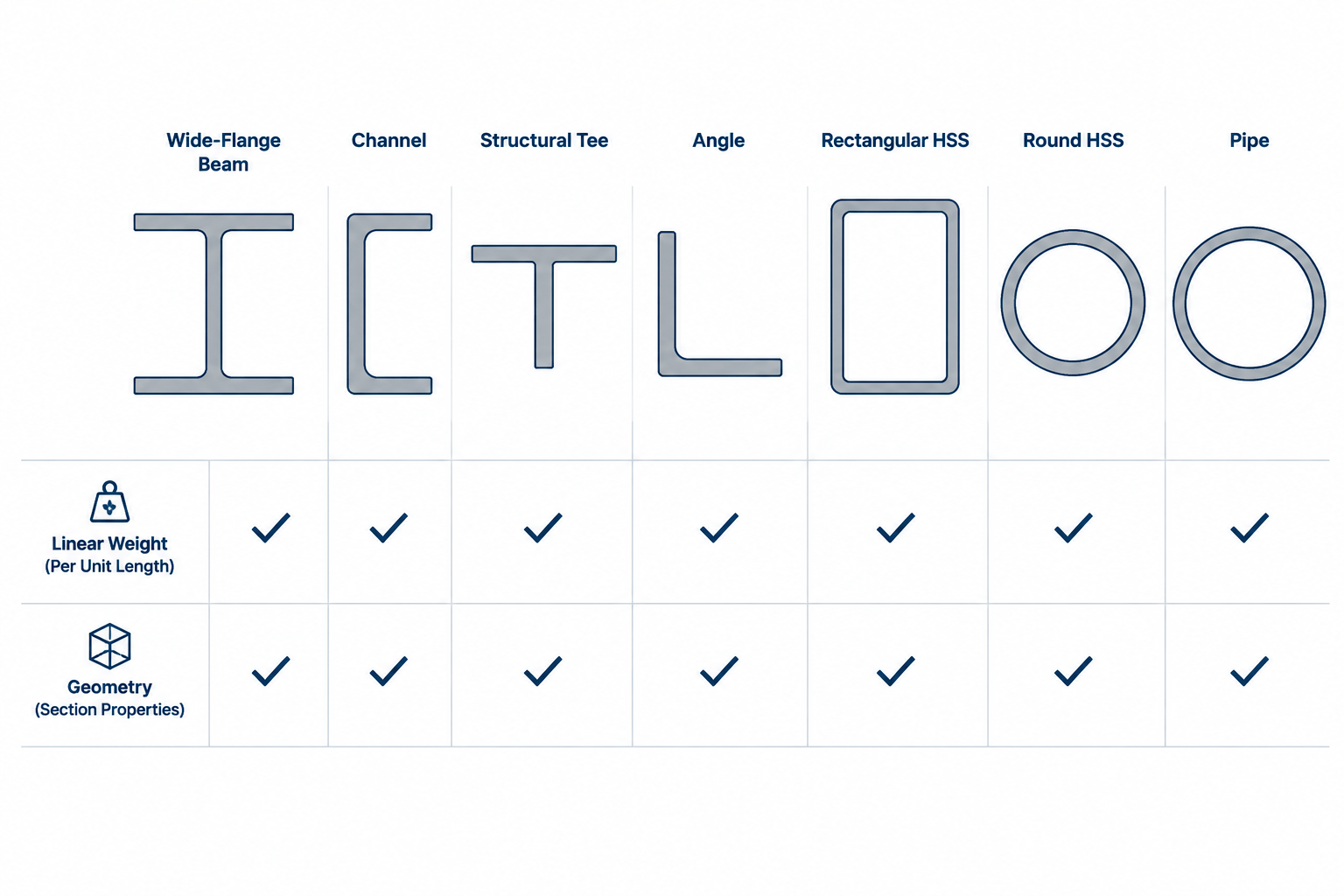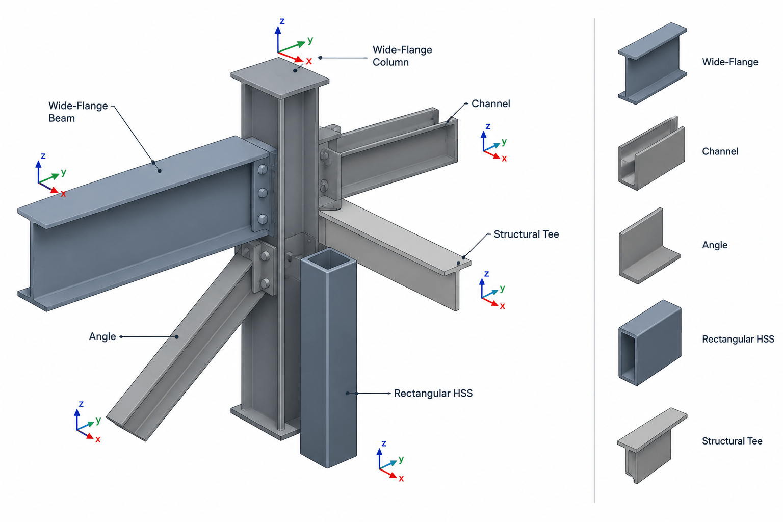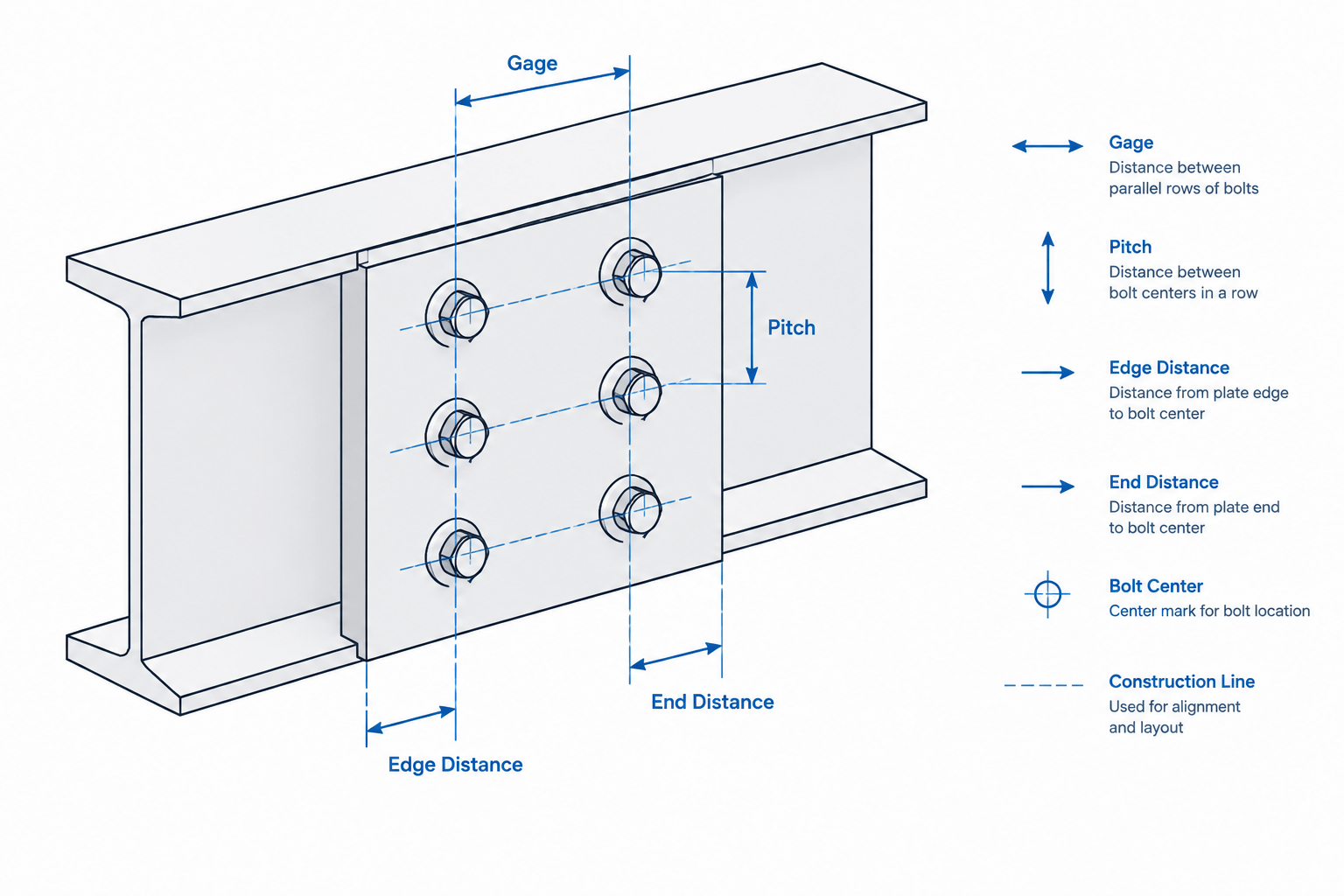
Structural steel connection drawings often describe bolt patterns with a small set of geometric terms: gage, pitch, edge distance, and end distance. These terms may look interchangeable when viewed as ordinary dimensions, but each describes a different relationship between holes, member edges, and the direction of the connection.
Correct bolt layout terminology helps designers communicate intent, allows detailers to build consistent shop drawings, and reduces mistakes when patterns are transferred into CAD or fabrication models. It does not, by itself, establish whether a connection is structurally adequate. Hole sizes, spacing limits, edge conditions, connection strength, installation access, and fabrication tolerances must be verified against the governing design documents and applicable requirements.
The basic bolt-pattern terms
| Term | Typical meaning in a steel connection | Common drafting direction |
|---|---|---|
| Gage | Transverse distance between bolt lines, or the location of a bolt line from a defined member datum | Across a flange, leg, plate, or other connected element |
| Pitch | Center-to-center spacing between consecutive fasteners in the longitudinal direction | Along the member or along the force-transfer direction |
| Edge distance | Distance from a hole center to the nearest adjacent material edge | Usually transverse to the bolt line |
| End distance | Distance from a hole center to the material end associated with the bolt line | Usually parallel to the member or connection length |
| Stagger | Longitudinal offset between fasteners in adjacent rows | Along neighboring bolt lines |
These definitions describe common detailing usage. A project may use different dimensioning conventions, so the drawing legend, typical details, and fabricator requirements remain important.
Gage: locating bolt lines across the material
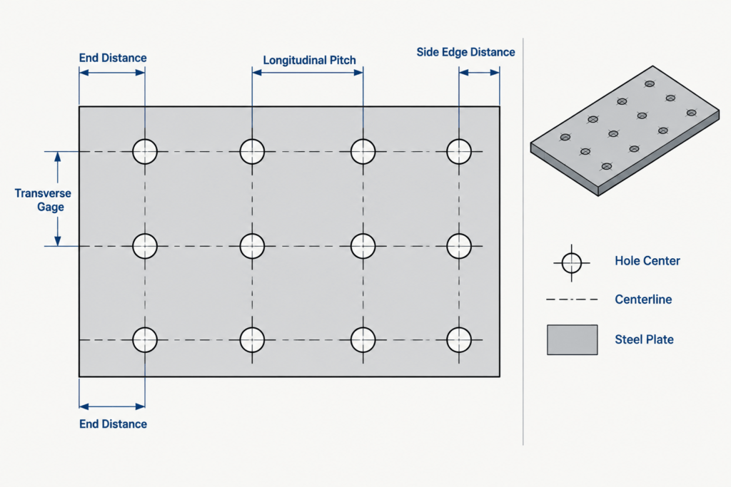
Gage generally describes bolt-line geometry across a connected part rather than along its length. In a plate with two parallel rows of holes, the gage is commonly the center-to-center distance between those rows. A drawing may instead locate each row from a centerline, plate edge, member back, or other established datum.
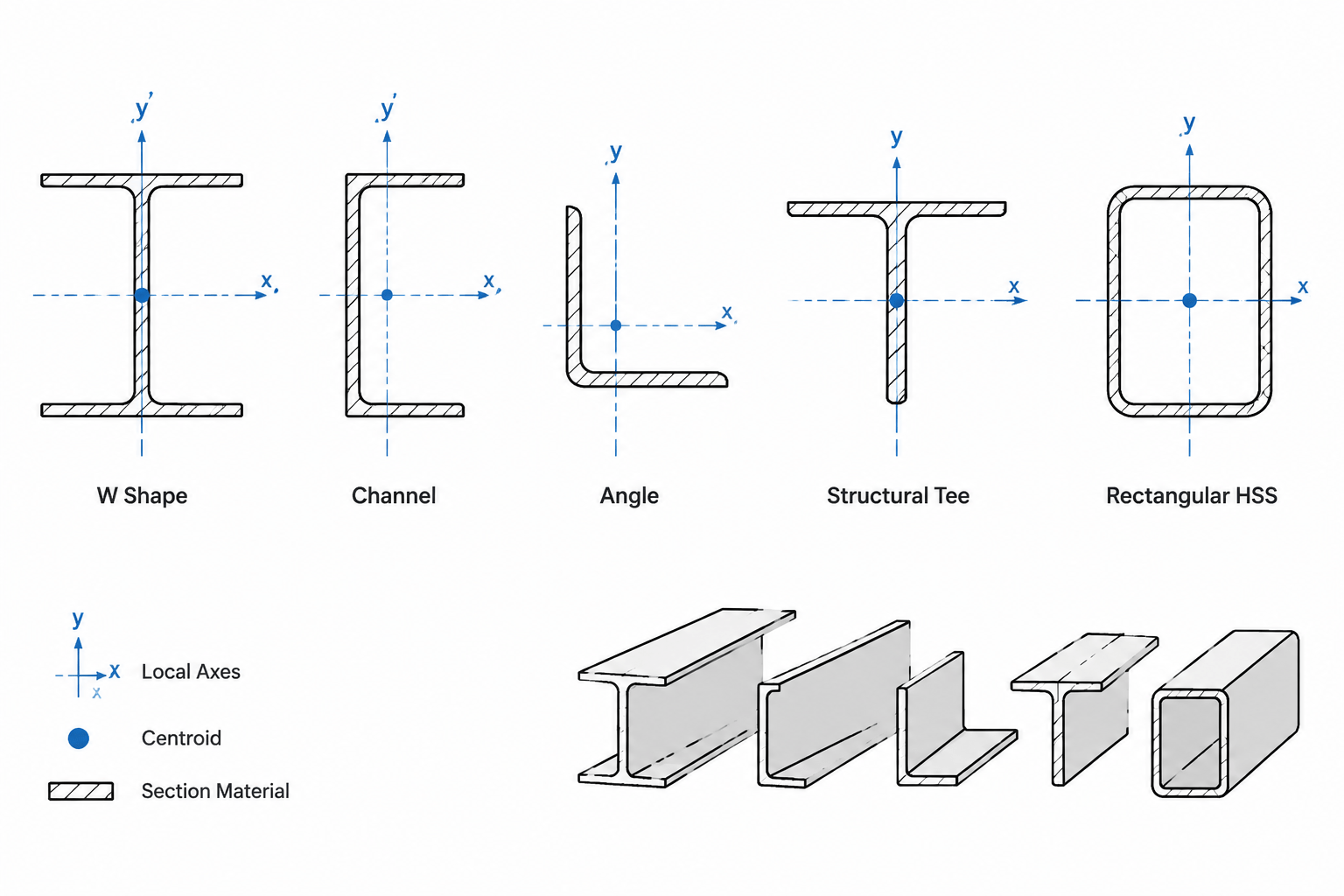
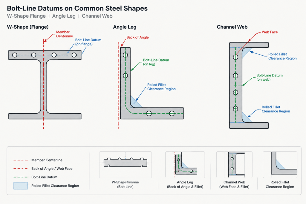
The datum matters. On a W-shape flange, bolt lines may be shown symmetrically about the web or member centerline. On an angle, a gage line may be located from the back of the connected leg. On a channel, dimensions may be referenced from the back of the web, the member centerline, or a connection-specific work line. The word gage alone does not identify the datum; the dimensions and drawing convention must do that.
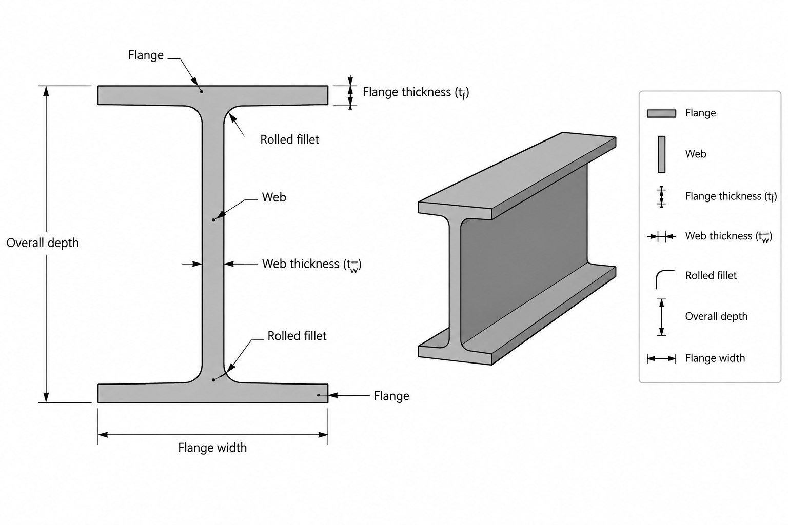
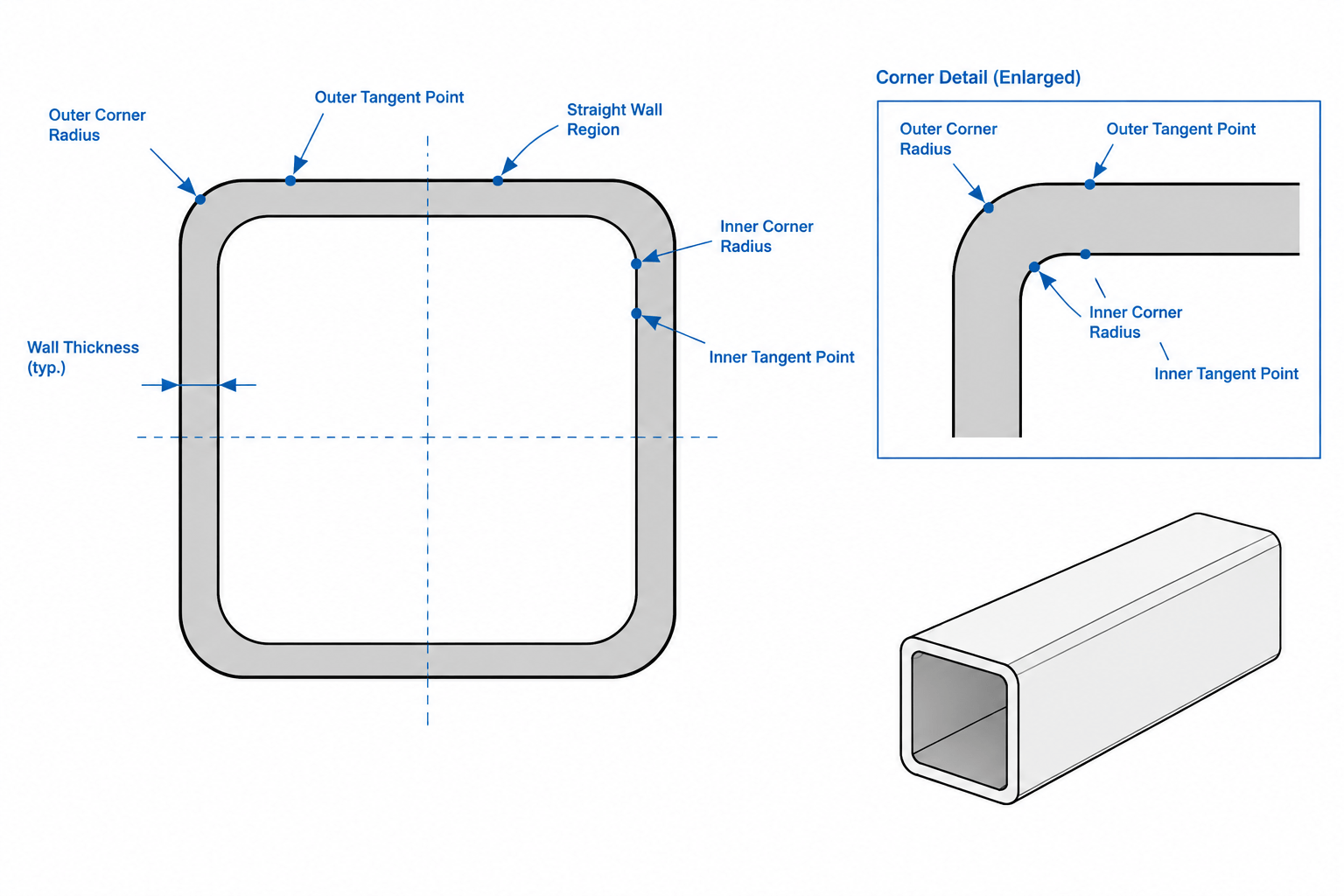
A gage must also be interpreted in relation to the actual shape geometry. Rolled fillets, flange slopes where applicable, rounded HSS corners, and angle heel regions can affect washer bearing, bolt installation, and available clearance. A bolt line that fits inside a simplified rectangular CAD outline may conflict with the real rolled section.
Pitch: spacing along a bolt line
Pitch is the center-to-center distance between successive holes along the primary direction of a bolt row. If several holes are equally spaced, a detail may show an equal-space notation rather than dimension every interval individually. If spacing changes, the drawing should make each segment or controlling location clear.
Pitch should not be confused with the total length of the pattern. A row containing multiple holes has spaces between the hole centers, plus an end distance at either end when the row terminates at material boundaries. Repeating a pitch value without checking the full dimension chain can shift the last hole or change the overall plate length.
In skewed or sloping connections, the intended direction of pitch needs special attention. The dimension may follow the bolt line rather than a global horizontal or vertical axis. CAD users should confirm whether the drawing shows a true aligned dimension or only a projected distance.
Edge distance and end distance
Both edge distance and end distance are normally measured from the center of a hole to a material boundary. The distinction is based mainly on orientation and connection context.
- Edge distance commonly refers to the side edge adjacent to a bolt row.
- End distance commonly refers to the boundary at the beginning or end of that row.
The measurement starts at the hole center, not at the edge of the hole. This distinction becomes important when different hole types or diameters are used. A clear drawing should identify the hole specification separately rather than relying on an edge dimension to imply hole size.
The physical condition of the boundary may also matter. A rolled edge, sawed end, sheared edge, or thermally cut edge may be treated differently by governing requirements or project specifications. Detailers should avoid assuming that all visible outlines represent equivalent edge conditions.
Staggered bolt patterns
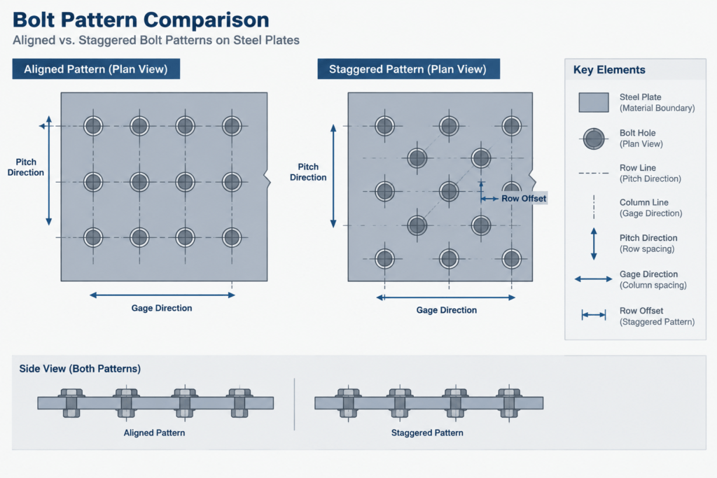
A staggered pattern places holes in adjacent rows at different longitudinal positions. Stagger can improve fit or provide a desired connection arrangement, but it introduces more geometry than a rectangular grid.
A staggered layout may require:
- gage between the rows;
- pitch within each row;
- longitudinal offset between rows;
- edge and end distances for the governing holes; and
- clear identification of which row begins nearest the member end.
Do not infer stagger solely from a drawing that appears offset on screen. The pattern should be dimensioned or otherwise defined. Apparent offsets can result from a skewed view, an incorrectly scaled reference, or a model displayed in projection.
How terminology changes with common steel shapes
W-shapes and other I-shaped members
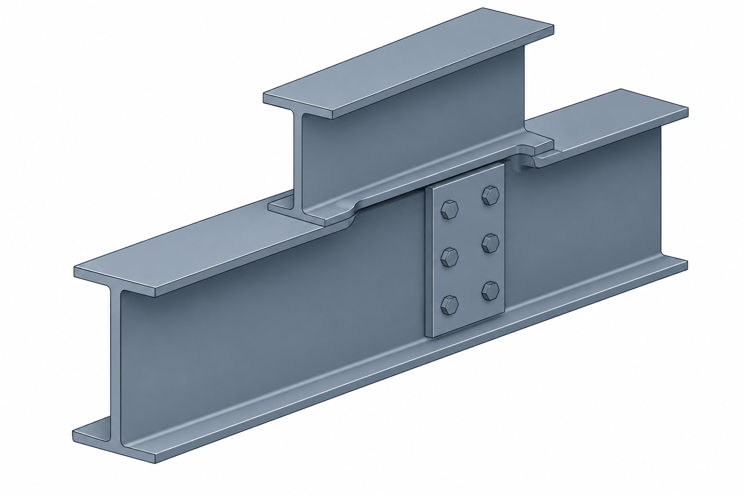
Flange holes are often organized around the web or member centerline, while web holes are arranged within the clear region between flange fillets. The nominal depth and flange width are not enough to establish a safe bolt pattern. Fillet-related detailing dimensions and tool access must also be considered.
Angles
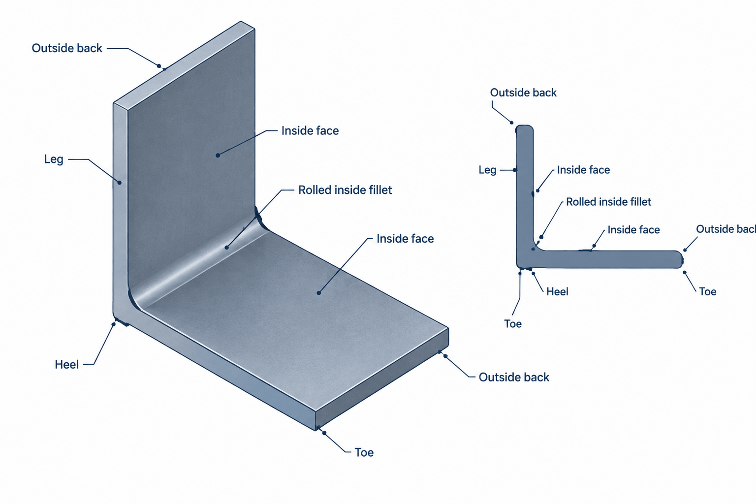
Angle hole locations are commonly described from the back of a leg, but orientation must be explicit. A mirrored angle can place the outstanding leg, heel, and toe on the wrong side even when the numerical gage remains unchanged. Show the angle orientation as well as the hole dimensions.
Channels
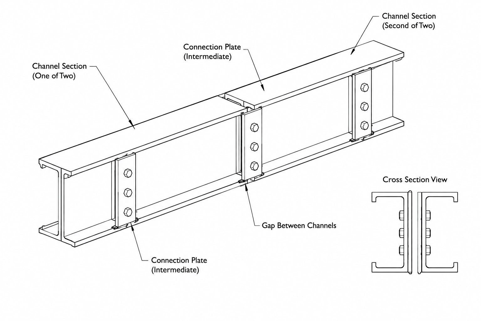
Channels are not symmetric about both principal axes. A pattern referenced from the back of the web is not interchangeable with one referenced from the member centroid. When channels are paired, verify whether dimensions control each individual channel or the built-up assembly.
HSS and box-shaped members
HSS connections require attention to corner regions, wall access, opposite-face interference, and the ability to install or tighten fasteners. Dimensions should be tied to identifiable faces or centerlines rather than an assumed sharp outside corner.
A reliable CAD layout workflow
- Establish the local connection axes. Define the longitudinal direction of the bolt rows and the transverse direction of the gage before placing holes.
- Choose stable datums. Use member centerlines, plate centerlines, backs of angles, web faces, or clearly identified material edges as appropriate.
- Draw actual section geometry where clearance matters. Include relevant fillets, corner regions, and adjacent parts rather than relying only on simplified outlines.
- Place hole centers first. Build the pattern from construction lines or constrained points, then apply the specified hole representation.
- Check the dimension chain. Confirm pitch, gage, end distances, edge distances, overall pattern length, and symmetry or stagger.
- Review installation access. Consider bolt heads, nuts, washers, tightening tools, welds, stiffeners, and nearby member surfaces.
- Label the hole information separately. Pattern geometry should not be expected to communicate hole type, diameter, or fabrication method.
- Compare plan, elevation, section, and model views. A pattern that looks correct in one view may be placed on the wrong face or mirrored in another.
Common bolt-layout drafting errors
- Dimensioning to a hole edge instead of the hole center.
- Calling longitudinal spacing a gage or transverse spacing a pitch.
- Using the member centroid when the shop convention references a physical face or back.
- Mirroring an angle or channel without updating the hole orientation.
- Ignoring rolled fillets or HSS corner regions in a simplified CAD block.
- Allowing equal-pitch notation and an overall dimension to conflict.
- Locating holes from both ends and creating a closed dimension chain that cannot accommodate fabrication variation.
- Copying a bolt pattern from a similar connection without checking member size, plate geometry, or erection access.
Geometry is not connection design
A well-dimensioned pattern can still be unsuitable for a real connection. Bolt spacing and edge geometry interact with several possible strength and service considerations, while hole type, loading direction, connected-part thickness, material, welds, and connection behavior may affect the design.
For that reason, CAD details and standard blocks should be treated as drafting starting points rather than automatically reusable designs. Before release for fabrication, the responsible project team should verify the connection geometry, structural design, applicable requirements, fabrication preferences, and field installation conditions.
Used consistently, the terms gage, pitch, edge distance, end distance, and stagger provide a compact language for defining bolt patterns. The key is to pair those terms with clear datums, accurate shape geometry, and unambiguous hole information.