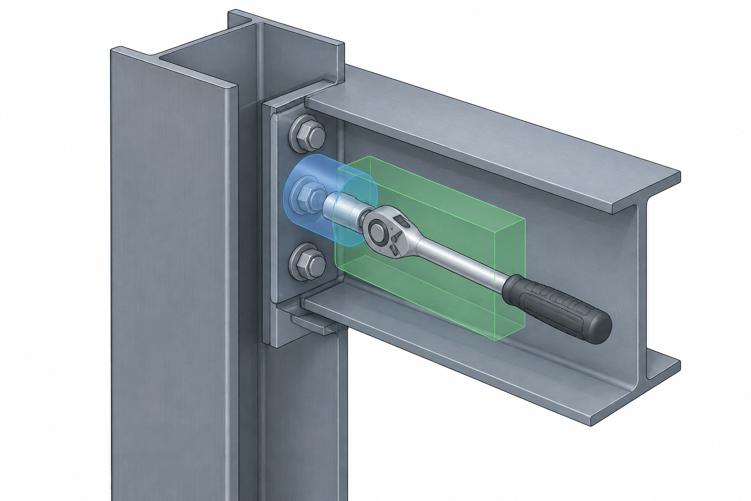
A bolt may fit through its hole while still being impossible to install or tighten. Structural steel bolt wrench clearance is the working space needed around a bolt assembly for the installer, wrench, socket, or other tightening equipment. It is a separate issue from bolt spacing, edge distance, hole clearance, and structural capacity.
Access problems commonly occur where bolts are close to beam flanges, column flanges, stiffeners, HSS walls, connection angles, welds, or projecting plates. These conflicts can remain hidden in a plan or elevation because the obstructing part lies outside the view. A useful connection model or shop drawing therefore needs to represent not only where the bolt is located, but also how the assembly will be inserted, held, and tightened.
Hole Clearance Is Not Wrench Clearance
A bolt hole provides clearance for the bolt shank. It does not confirm that the bolt head, nut, washer, socket, or wrench can be placed and operated. Several different checks are involved:
- Hole fit: Can the bolt pass through the aligned plies?
- Assembly fit: Is there room for the bolt head, nut, and required washers to seat against the connected material?
- Tool placement: Can the selected wrench or socket engage the head or nut?
- Tool operation: Can the tool turn, react, or otherwise complete the specified tightening procedure?
- Installation path: Can the bolt be brought into position without striking another member or trapped component?
A connection can satisfy the first check and fail any of the others. Increasing the hole size is not a general solution to a tool-access problem. Hole type is a design and specification matter, while wrench access is primarily a geometry and constructability matter.
Consider the Entire Bolt Assembly
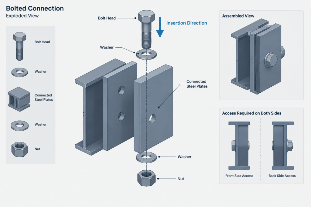
In simplified CAD symbols, a bolt may appear as a circle in plan or a line through a plate stack. The physical assembly occupies more space. Depending on the specified connection, it may include a head, shank, nut, and one or more washers. The tightening method may also require equipment extending beyond the visible hardware.
The detailer should evaluate both faces of the connection. If a wrench must hold one side while another tool operates on the opposite side, both sides need access. It is not enough to show clear space around the nut if the bolt head is trapped behind a flange or adjacent plate.
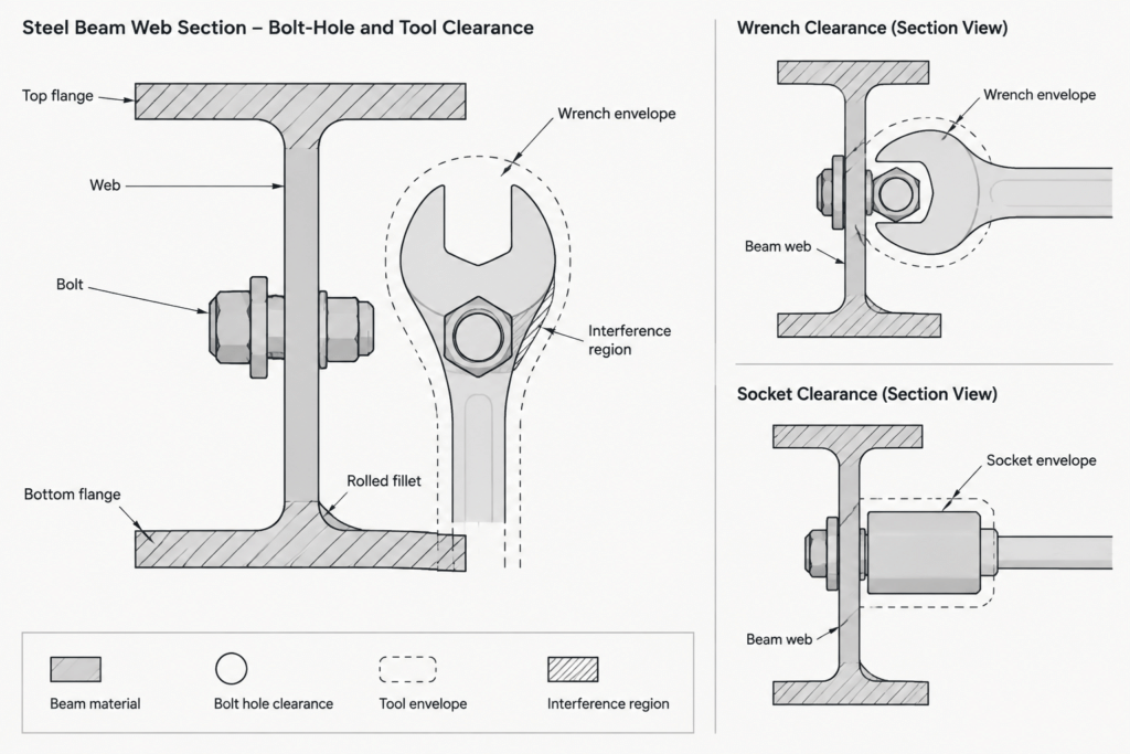
The bolt length and direction of insertion matter as well. A bolt shown in its final position may look unobstructed even though there is no straight path for inserting it. Nearby deck, cladding supports, piping, concrete, or another steel member may be installed before the connection is completed. The intended erection sequence can therefore affect which side should receive the bolt head.
Common Structural Steel Clearance Conflicts
Bolts near beam flanges
Web connection bolts placed near the top or bottom flange can be difficult to reach because the flange limits the space available to the tool. Rolled fillets and flange slope, where applicable to the selected shape, further reduce the usable region. Checking only the clear web depth or a flat two-dimensional outline can miss these obstructions.
Bolts beside column flanges
A beam connection close to a column flange may leave a narrow pocket between the bolt and column surface. The bolt center may satisfy the drawing dimensions while the nut or wrench overlaps the column flange. This is especially easy to overlook when connection plates are viewed only from the beam side.
Stiffeners and doubler plates
A stiffener added during connection development can block access to bolts that were previously workable. The conflict may involve the stiffener plate itself, its weld, or the space needed to place a socket over the hardware. Connection components should be coordinated as a complete assembly rather than checked as isolated details.
Angles and channels
The outstanding and connected legs of an angle create different access conditions. A bolt near the heel may be affected by the rolled fillet, while a bolt near the toe may have adequate seating space but limited wrench swing. Channel flanges can similarly create confined spaces on the inside face of the section.
HSS connections
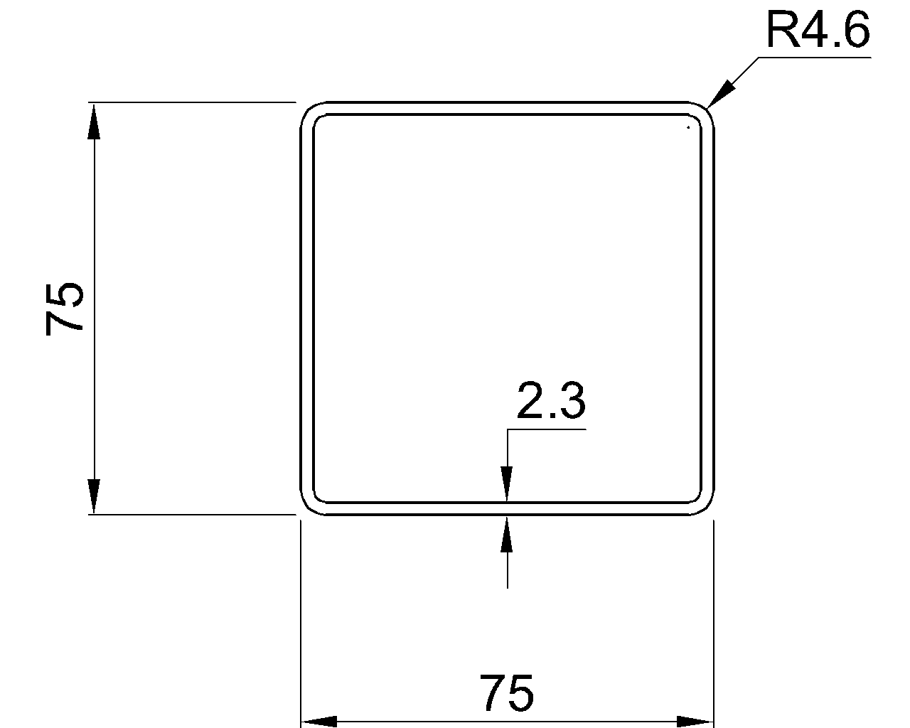
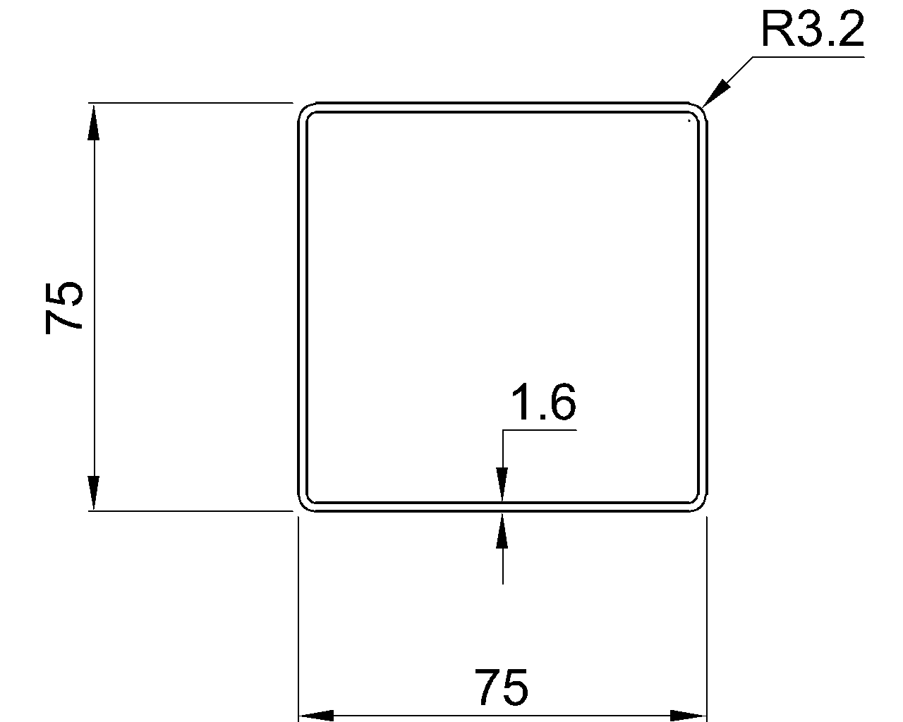
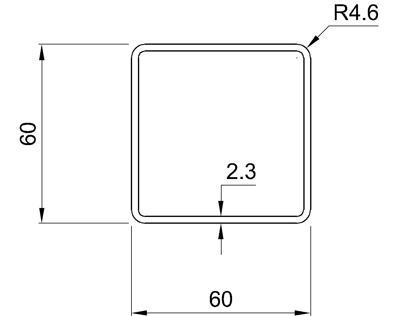
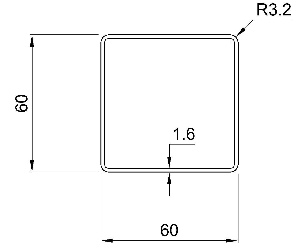
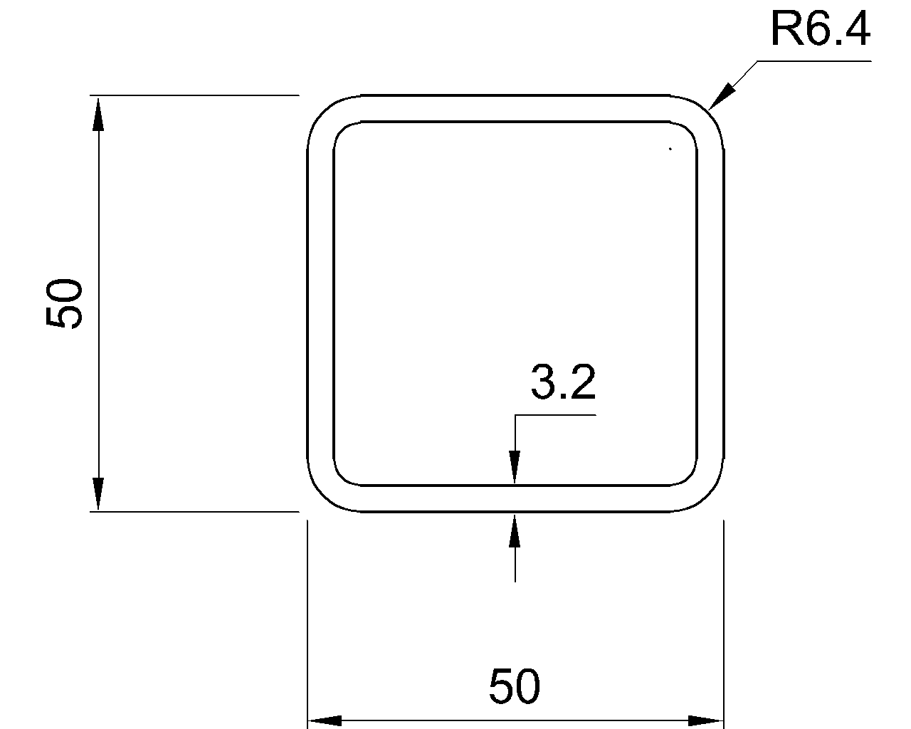
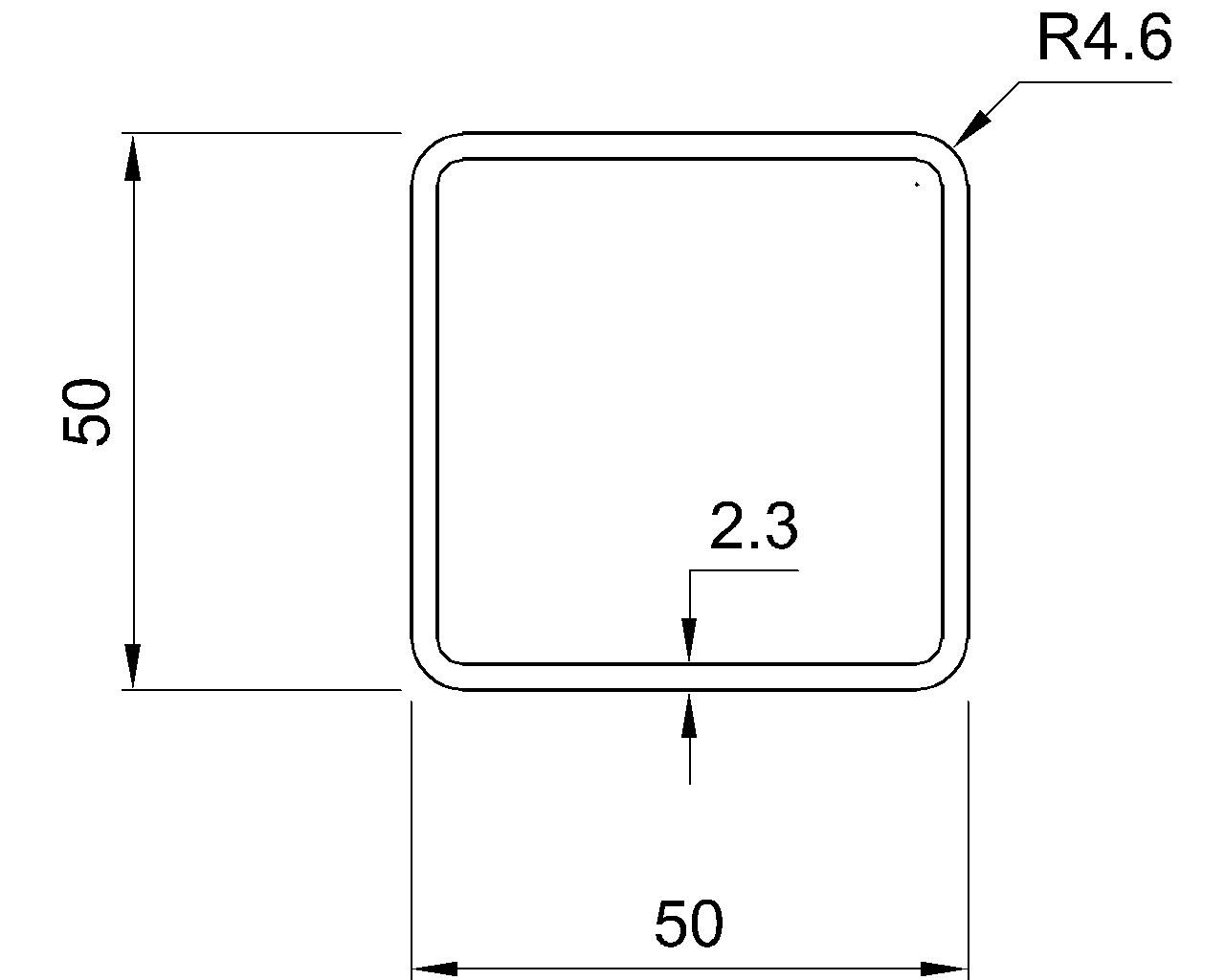
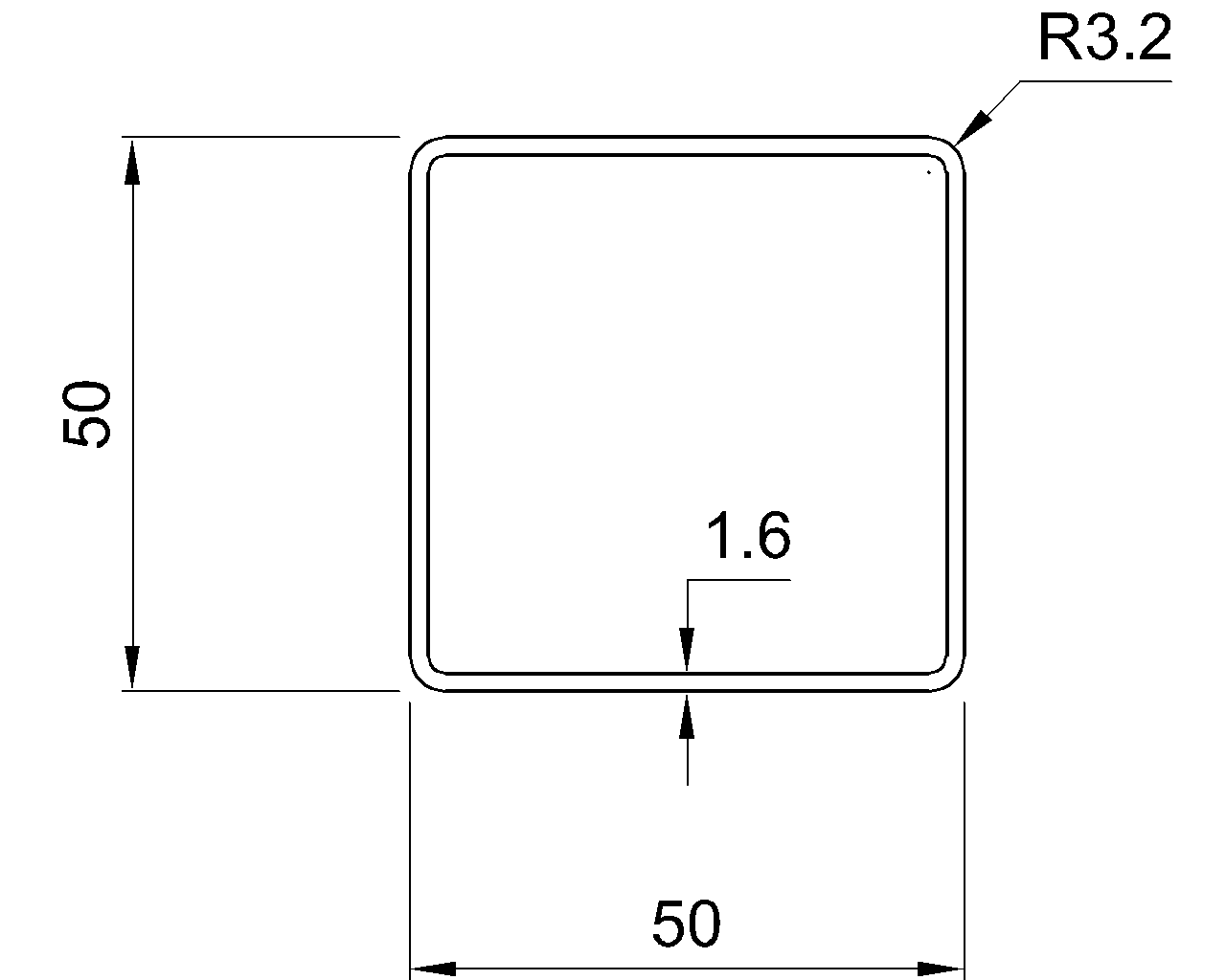
Ordinary bolts generally require access to both the head and nut. A closed HSS member does not provide interior access after fabrication unless the connection has been deliberately configured for it. Access openings, through-bolts, internal plates, threaded components, or specialized fastening systems must not be assumed. They require project-specific design, detailing, fabrication, and installation decisions.
Welds and surface transitions
A nut or washer should not be unintentionally seated on a weld profile, rolled fillet, plate edge break, or other uneven transition. Even when the hardware itself clears, a nearby weld may prevent the tool from seating squarely. Weld access and bolt access should be reviewed together.
Tool Access Depends on the Tightening Method
There is no single universal wrench-clearance envelope suitable for every structural steel connection. Required space depends on the hardware, bolt diameter, wrench or socket configuration, and specified installation method. Manual tools, powered tools, and specialized pretensioning systems can require different access and reaction space.
For this reason, a CAD office should avoid treating an unverified generic clearance circle as a code requirement. A clearance template can be useful as an internal coordination aid, but its source, assumptions, and intended tool type should be documented. When access is close, the fabricator or erector should confirm the proposed arrangement using the actual installation equipment and project requirements.
| Geometry check | Question to ask | Typical obstruction |
|---|---|---|
| Hardware seating | Can the head, nut, and washers bear on the intended surfaces? | Fillet, weld, plate edge, or sloped surface |
| Socket placement | Can the tool align with and fully engage the hardware? | Flange, stiffener, angle leg, or adjacent bolt |
| Tool operation | Is there room to turn or react the tool? | Member face or confined connection pocket |
| Bolt insertion | Can the full bolt length enter along its installation path? | Deck, wall, HSS face, or perpendicular member |
| Opposite-side access | Can the other end of the assembly be held or inspected? | Closed section, concrete, or inaccessible cavity |
A Practical CAD and Detailing Workflow
Begin with the actual section geometry rather than a simplified bounding box. Include flanges, webs, HSS walls, connection plates, and relevant rolled fillets. Add the bolt assembly on both faces of the connected material, with the intended head and nut orientation.
Next, review the connection in the views that reveal the confined space. A plan may show side clearance, while a section through the bolt line reveals interference with a flange. A three-dimensional model can help, but it does not replace a deliberate installation-path check. Hardware displayed only as symbolic cylinders may understate the required working space.
Where the office uses tool-clearance objects, place them on a dedicated nonprinting layer or assign them a distinct model category. Label the assumed tool or purpose so another user does not mistake the envelope for physical steel. Clearance objects should be easy to update when the bolt size, hardware arrangement, or installation method changes.
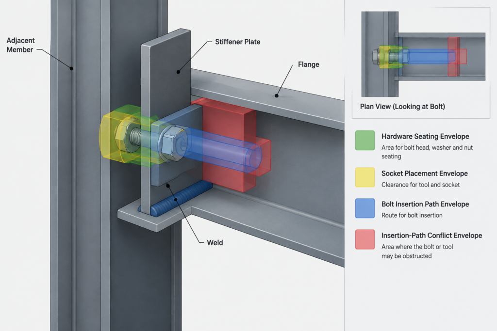
Review the connection again after stiffeners, welds, edge returns, slab edges, and nearby framing have been added. Access that appears adequate during preliminary layout may disappear as the detail develops.
Ways to Resolve an Access Conflict
The appropriate solution depends on engineering requirements and fabrication preferences. Possible coordination options include:
- Reorienting the bolt so the head and nut are on more accessible sides.
- Adjusting the bolt line while maintaining all required design and detailing constraints.
- Changing the connection plate or angle geometry.
- Revising a stiffener termination or weld layout with engineering approval.
- Changing the erection or assembly sequence.
- Using different approved hardware or a different connection concept.
Do not independently substitute a slotted hole, smaller bolt, reduced washer arrangement, field weld, access hole, or specialized fastener merely to make the geometry work. Such changes may affect strength, slip behavior, fabrication, inspection, durability, or the intended load path and require appropriate review.
What Shop Drawings Should Communicate
Shop drawings should make bolt orientation and access-sensitive geometry understandable. Sections or enlarged details are useful when a standard view hides the relationship between hardware and nearby steel. If installation depends on a particular bolt direction, sequence, access opening, or removable component, the requirement should be communicated rather than left to inference.
Dimensions should control the connection geometry, not the temporary tool-clearance graphics used during modeling. Notes should also avoid guaranteeing that a connection is installable unless the actual hardware, equipment, sequence, and field conditions have been verified.
Final Review Checklist
- Check the bolt head, nut, washers, and connected plies rather than the hole alone.
- Confirm access on both sides of the connection.
- Review the straight-line bolt insertion path.
- Account for rolled fillets, weld profiles, stiffeners, and adjacent members.
- Check the intended tightening method and tool configuration.
- Coordinate access with fabrication and erection sequence.
- Recheck the connection after design revisions and member substitutions.
- Refer unresolved conflicts to the responsible designer, fabricator, or erector.
Wrench clearance is a small geometric issue with significant shop and field consequences. Treating installation access as a distinct detailing check helps prevent trapped bolts, improvised field changes, delayed erection, and connections that exist in CAD but cannot be assembled as shown.