A structural steel member can have correct section dimensions and still be located incorrectly in a model or shop drawing. The problem often begins with reference geometry: one person is locating a beam by its centerline, another is measuring from the face of support, and a third is using the physical cut end. These references may be close together on a drawing, but they do not represent the same thing.
Understanding structural steel work points, member lines, setbacks, and connection planes is essential when converting design drawings into fabrication geometry. These concepts also explain why inserting an accurate W-shape, HSS, channel, angle, or tee profile is only the first step in a reliable CAD workflow.
What Is a Structural Steel Work Point?
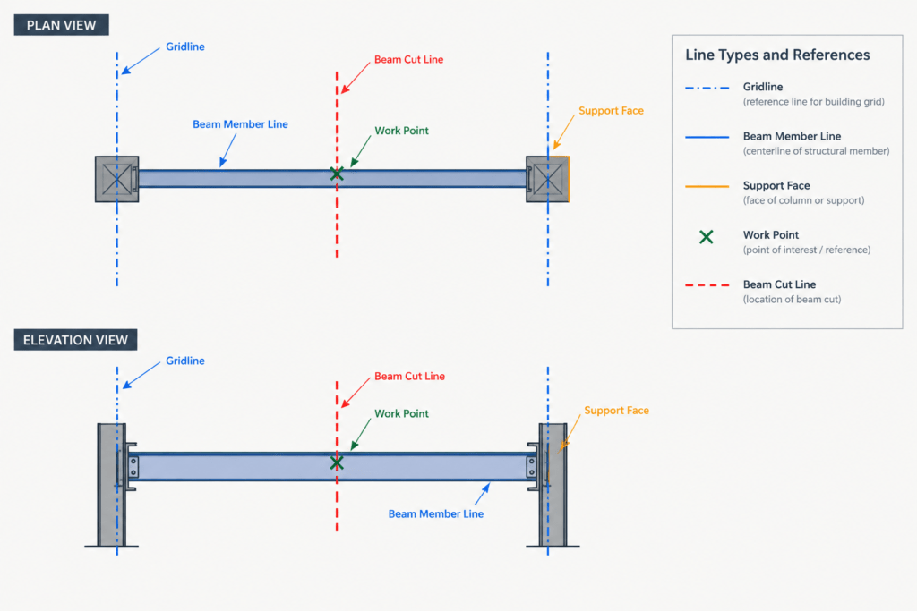
A work point is a theoretical reference point used to establish structural geometry. It commonly occurs where two or more layout lines intersect, such as a beam line meeting a column line or a brace line meeting a beam-column joint.
The work point is not necessarily located on a physical steel surface. It may fall inside a column, beyond the cut end of a brace, or at the intersection of lines that are visible only in the analytical or layout model. Its purpose is to provide a stable geometric reference from which members and connections can be developed.
A work point may be defined by:
- The intersection of member centerlines
- The intersection of structural gridlines
- A framing line meeting a column line
- The intersection of brace working lines
- A designated elevation and plan coordinate
- Project-specific reference geometry shown on the design drawings
There is no universal rule that every work point must lie at the centroid of a member. The controlling reference should be confirmed from the project drawings, model conventions, and detailing instructions.
Member Centerline Versus Work Line
A member centerline is a line used to locate a member along its length or within a framing system. For symmetrical shapes, it may coincide with one or both centroidal axes in cross-section. For unsymmetrical framing, offset connections, or members oriented eccentrically, the project work line may not pass through the section centroid.
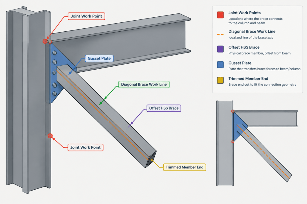
Braces provide a common example. A brace work line often represents the intended line of action between joint work points. The actual member may be offset from that line because of gusset plate geometry, connection clearance, or the way an angle, channel, or HSS is attached. Moving the physical member does not automatically move the theoretical work line.
Likewise, a beam line shown in plan may represent a gridline, web centerline, member centerline, or another defined framing reference. A drafter should not infer the intended meaning solely from how the line looks.
Key Reference Terms That Should Not Be Interchanged
| Reference | What it represents | Typical detailing use |
|---|---|---|
| Gridline | A project layout axis used to coordinate the structure | Locating columns, walls, framing bays, and major geometry |
| Work point | A theoretical point controlling member or joint geometry | Establishing beam, column, and brace intersections |
| Member line | A longitudinal reference assigned to a structural member | Placing and orienting the member in plan, elevation, or a model |
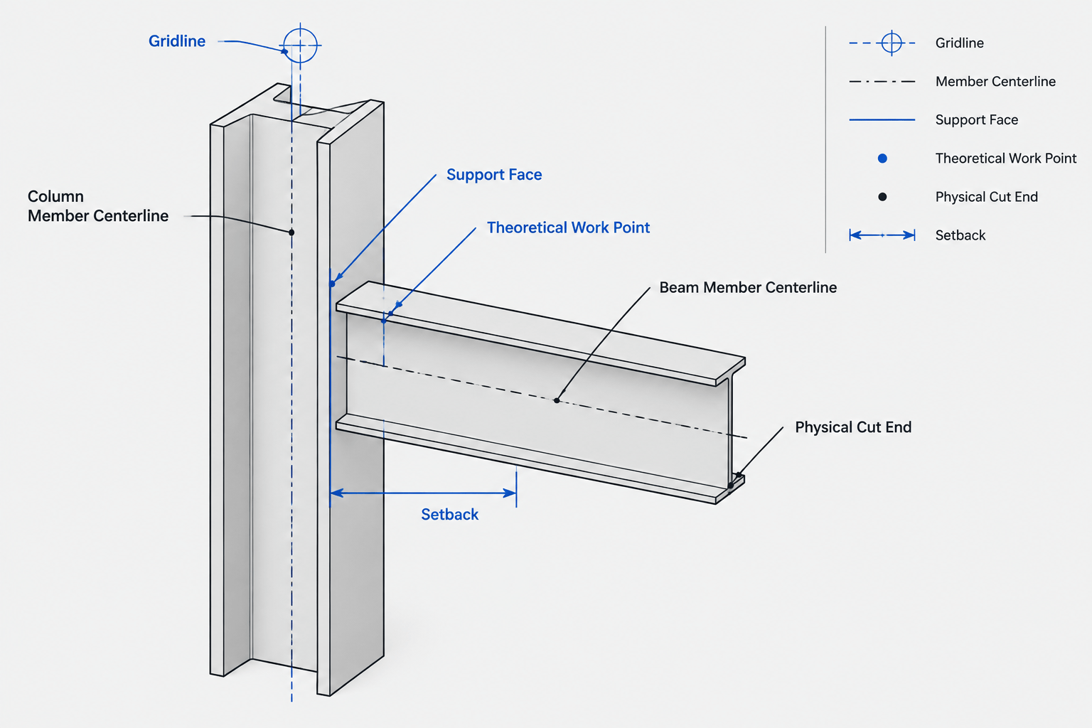
| Face of support | The physical or nominal plane at the supporting element | Checking clear distance, bearing, framing limits, and connection layout |
| Connection plane | The plane in which connected parts or fasteners are developed | Locating plates, clip angles, shear tabs, gussets, or end plates |
| Setback | The distance from a controlling reference to the member end | Establishing beam or brace cut length and connection space |
| Cut line | The physical termination of fabricated material | Producing shop dimensions and CNC-ready geometry |
These references can coincide, but coincidence should be demonstrated rather than assumed. For example, a beam end may align with a support face in one condition and stop short of it in another to provide connection clearance.
What a Steel Member Setback Controls
A setback separates theoretical layout geometry from the physical end of a member. In a simple framing condition, it may be measured from a work point, column line, support face, or another defined plane to the beam end. The exact origin of the setback must be clear because the same stated distance produces different cut lengths when measured from different references.
Setbacks create space for connection material and erection clearance. They can also accommodate skewed framing, sloped members, gusset plates, end plates, stiffeners, weld access, or supporting-member geometry. A setback is therefore part of the connection development, not merely an arbitrary shortening of the member.
Do not use a familiar office default without checking the actual condition. Connection type, member orientation, support geometry, fabrication method, and project requirements can all affect where the cut line belongs.
Why Sloped and Skewed Members Need Extra Care
Orthogonal plan views can conceal errors that become obvious in true-length geometry. When a member is sloped, skewed, or both, dimensions projected onto plan or elevation may differ from distances measured along the member axis.
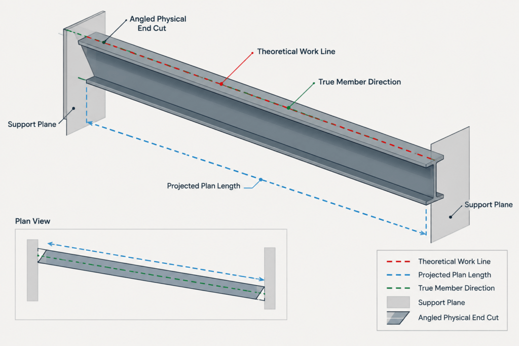
A reliable workflow distinguishes among:
- Horizontal plan distance
- Vertical elevation difference
- Projected length in a drawing view
- True member length along the work line
- Physical cut length after end preparation
The end plane also matters. A square cut perpendicular to the member axis does not create the same geometry as a vertical, horizontal, skewed, or compound cut. The detailing model should represent the intended end plane before connection plates, holes, and weld boundaries are finalized.
For diagonal bracing, establish the joint work points and brace work line first. Then place the selected section relative to that line according to the connection concept. Trimming the brace before resolving its orientation can produce incorrect edge distances, gusset overlap, or member length.
A Practical CAD and Modeling Workflow
1. Establish controlling layout geometry
Begin with grids, levels, support axes, and explicitly identified work points. Keep this reference geometry on dedicated layers or in model categories that are visually distinct from physical steel.
2. Confirm what each framing line means
Determine whether a line represents a web centerline, section centroid, outside face, top-of-steel alignment, or another project reference. Record the convention rather than relying on memory.
3. Place members using actual section geometry
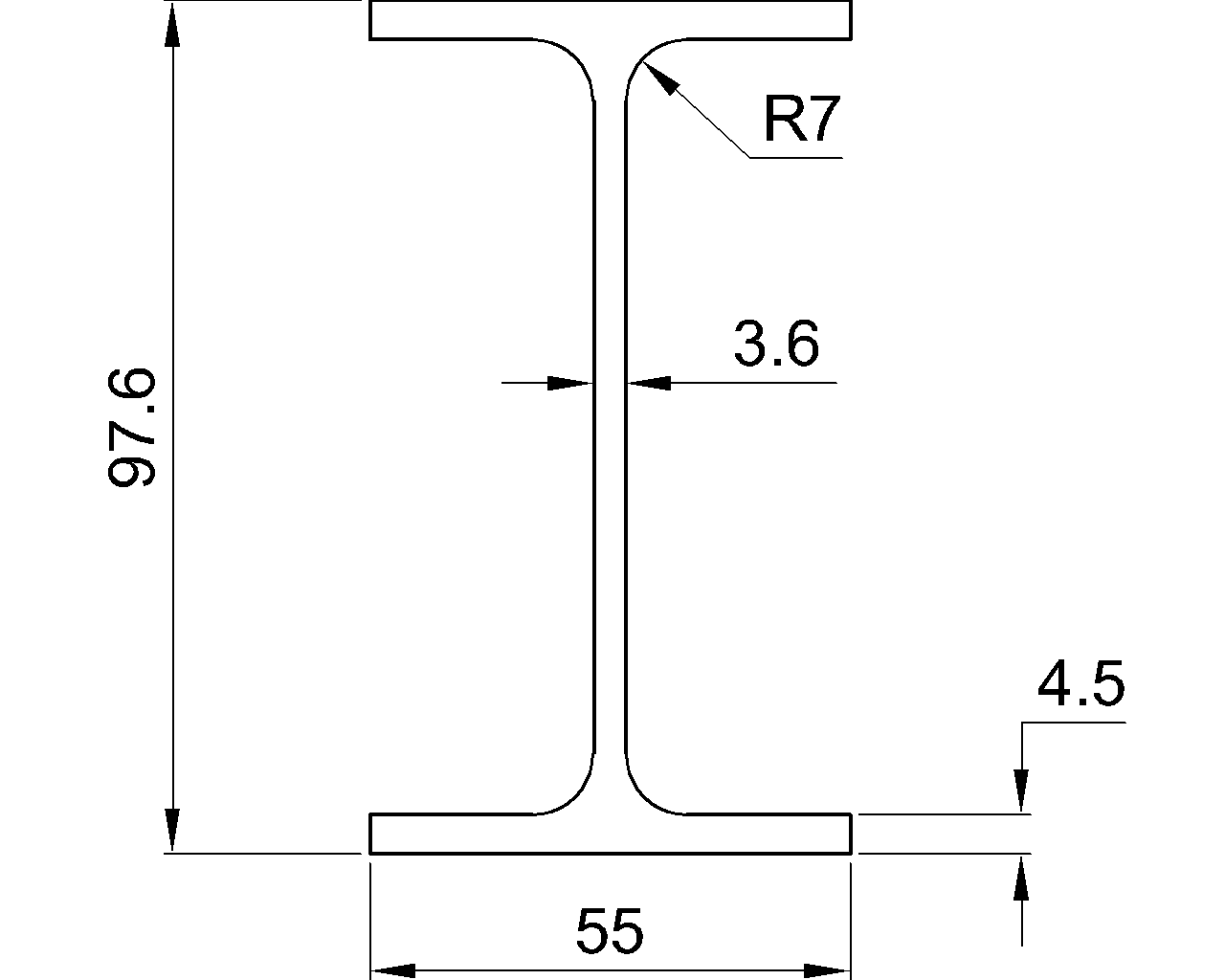
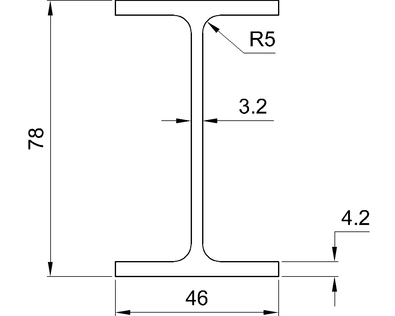
Insert or model the correct shape and orientation. Check flange direction, web direction, HSS rotation, angle leg orientation, channel toe direction, and tee stem orientation. Shape database dimensions define the cross-section; they do not define its project location.
4. Develop the connection zone
Identify the support face, connection plane, available clearance, and member end condition. Add plates, angles, gussets, or other conceptual connection geometry only after the controlling references are understood.
5. Create the physical cut geometry
Apply the required setback and end-plane orientation. Verify that the resulting member length is measured between the intended physical endpoints, not merely between layout points.
6. Check views and coordinates
Review the condition in plan, elevation, section, and a three-dimensional view when available. A member that appears correct in one projection may be offset or cut incorrectly in another.
7. Dimension from stable references
Use grids, work points, levels, support faces, and other clearly defined origins. Avoid chained dimensions when accumulated changes could obscure the controlling location.
Common Detailing Errors
- Treating the work point as the cut end: This omits the setback and can leave no space for the connection.
- Assuming every plan line is a member centerline: Some drawings use gridlines, web lines, or edge references.
- Centering unsymmetrical shapes automatically: Angles, channels, and tees may be positioned by a leg, web, stem, back, or connection plane instead.
- Measuring a sloped member only in plan: The projected distance is not the true length.
- Applying a standard-looking end cut to skewed framing: The required end plane depends on the actual support and connection geometry.
- Letting connection graphics control the member line: The theoretical structural geometry should be established before secondary connection parts are fitted around it.
- Using CAD blocks as placement authority: A shape block can represent section geometry accurately while containing no information about grids, elevations, work points, or project tolerances.
What to Verify Before Releasing a Detail
Before a member or connection detail is issued for review, confirm the following:
- The controlling gridlines, levels, and work points are identified.
- The meaning of each member line is understood.
- The steel shape and orientation match the framing intent.
- Offsets between the work line and physical section are shown where applicable.
- Setbacks are measured from named reference planes or points.
- Sloped and skewed lengths have been checked in true geometry.
- Cut-end planes agree with the connection configuration.
- Dimensions do not conflict between plan, elevation, section, and model views.
- Connection assumptions that require engineering confirmation are clearly flagged.
Reference Geometry Is Part of the Detail
Work points and member lines may not appear in the finished structure, but they control where the steel is fabricated and erected. Keeping theoretical layout geometry separate from physical section geometry makes models easier to revise, drawings easier to interpret, and connection conflicts easier to identify.
A sound structural steel CAD workflow therefore moves in a deliberate order: establish references, place the section, define the connection zone, apply setbacks, create cut geometry, and verify the result in multiple views. This approach is more dependable than trimming shapes until a drawing merely looks correct.