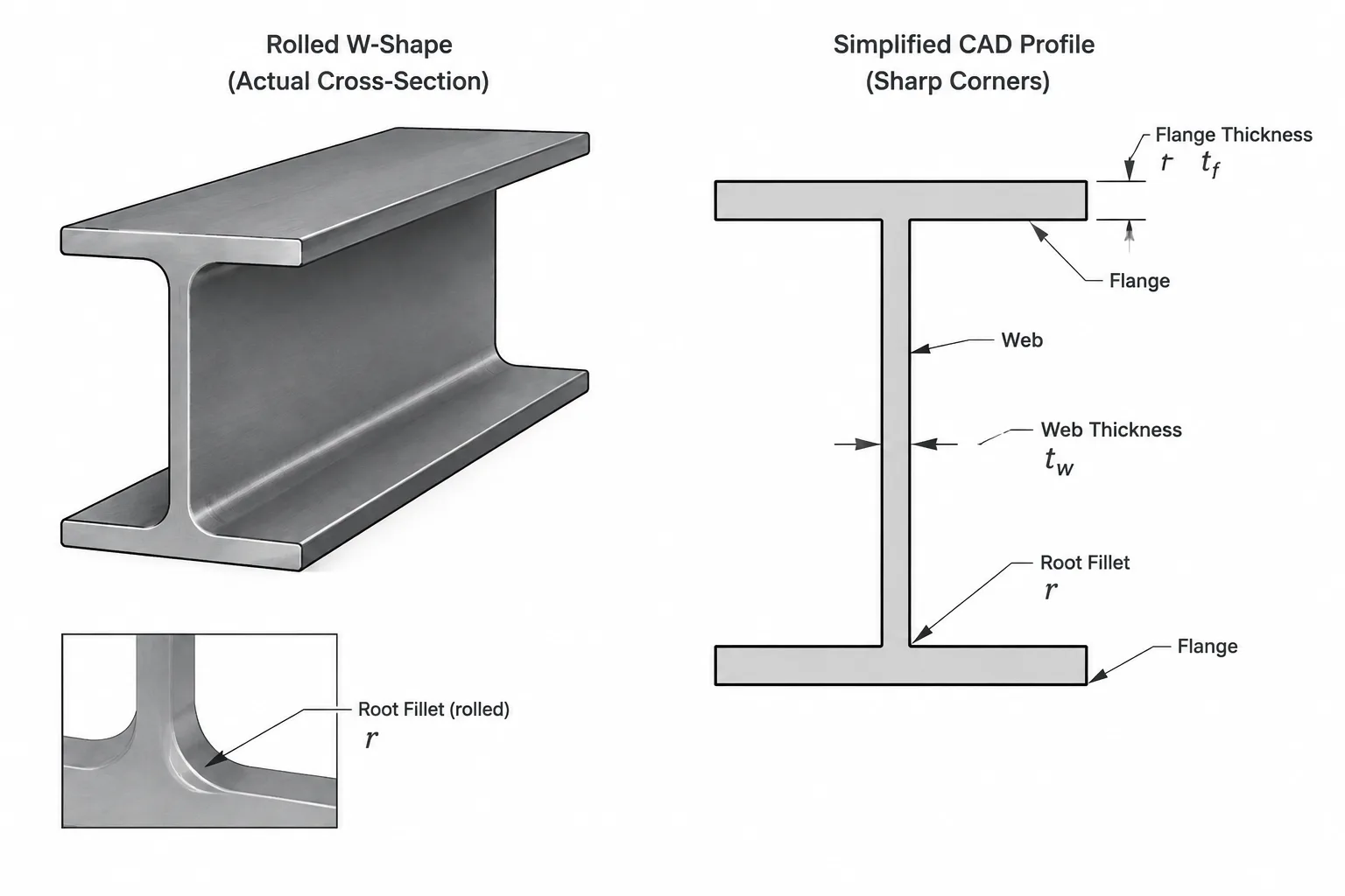
Web thickness and flange thickness appear to be simple dimensions, but they are frequently misused when structural steel shapes are modeled, compared, or detailed. In shape tables, the symbols tw and tf generally identify the web and flange thicknesses of an I-shaped section. Those values are useful for many tasks, but they do not describe every part of the rolled profile.
A rolled shape includes flange surfaces, web faces, root fillets, flange edges, and permitted dimensional variation. A drafter who treats the section as three sharp-cornered rectangles may create misleading clearances or connection geometry. Correct use of thickness data therefore begins with understanding what each value represents—and what it does not.
What tw and tf Mean
For a typical W-shape, tw is the published web thickness and tf is the published flange thickness. The web is the central plate-like portion connecting the flanges. The flanges are the wider elements at the top and bottom of the section when it is shown in its conventional orientation.
These dimensions are commonly used when checking:
- Plate and angle fit against the web or flange
- Available space for bolts, welds, stiffeners, and connection material
- Clear web depth between flange regions
- Approximate section geometry in analysis or CAD
- Local width-to-thickness relationships
- Material quantities for preliminary calculations
Published thicknesses should be read using the definitions associated with the applicable shape data source. A database label alone is not enough when the origin, units, or geometric conventions are unknown.
The Web Is Not an Isolated Rectangle
In a simplified drawing, the web may look like a rectangular plate extending from one flange to the other. A real rolled profile is different. Curved transition regions connect the web to the flanges, so the straight, unobstructed part of the web is less than the full distance between the nominal flange faces.
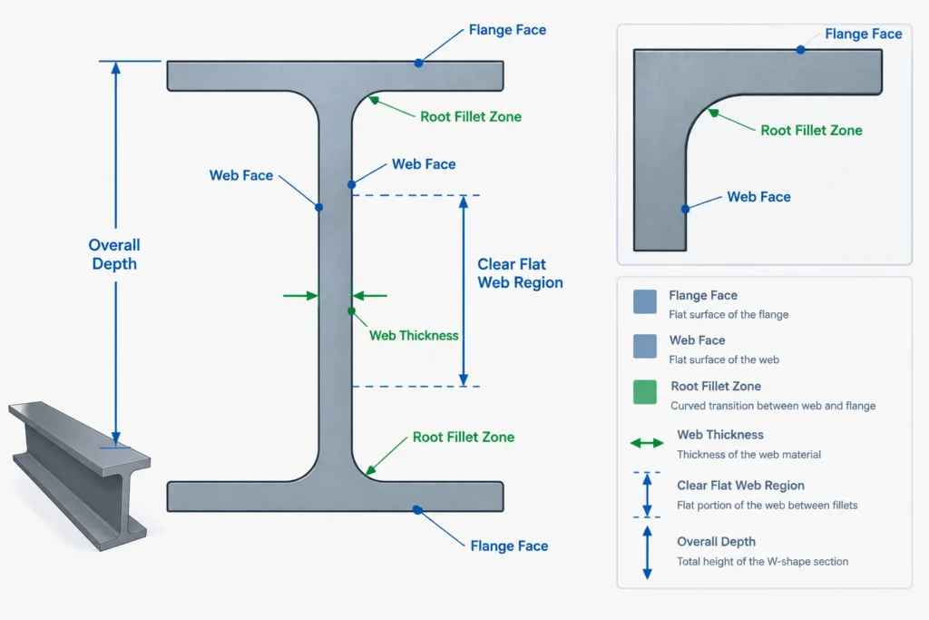
This distinction matters when placing connection plates, transverse stiffeners, welds, or bolt holes near a flange. A detail may clear the nominal web faces but still interfere with the rolled fillet. Web thickness does not define the size of that fillet or the usable flat region beside it.
For accurate fit-up work, consult the relevant detailing dimensions in addition to tw. Depending on the reference, these may describe the fillet zone, the distance from the flange surface to the web-to-flange transition, or a recommended clearance envelope. Do not derive such dimensions from web and flange thickness alone.
Flange Thickness Is Not the Same as Overall Flange Geometry
Flange thickness describes the thickness of the flange element, but it does not by itself define the flange width, edge shape, root transition, or slope. For W-shapes, the flange faces are treated as generally parallel for common drafting and design purposes. Other I-shaped rolled sections may have tapered flange surfaces, making a single rectangular-flange model less representative of the actual profile.
The outer flange edge can also include rolling geometry that is not captured by a sharp rectangular outline. This is usually unimportant in a framing plan but may matter for tight-fitting components, scanning comparisons, fabrication clearances, or highly detailed models.
Whenever flange thickness is being used to locate another component, identify the controlling surface. A dimension from the top of steel to the underside of the flange is not interchangeable with a dimension from the member centerline unless the section depth, orientation, and reference convention are all confirmed.
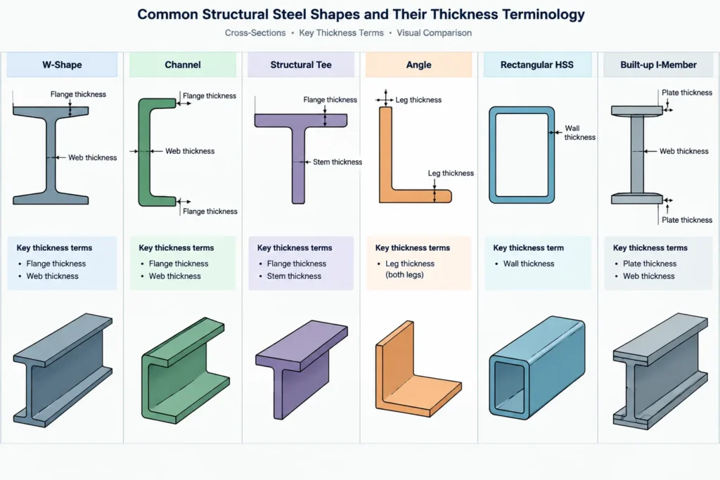
How Thickness Terminology Changes by Shape Type
| Shape family | Typical thickness terminology | Practical caution |
|---|---|---|
| W-shapes and related I-sections | Web thickness tw and flange thickness tf | Root fillets occupy part of the apparent web-to-flange corner. |
| Channels | Web and flange dimensions may be listed separately | The section is unsymmetric about one principal direction, and flange geometry must be oriented correctly. |
| Structural tees | Stem thickness and flange thickness | The tee may originate from a split parent shape; verify the published tee geometry rather than assuming an ideal cut. |
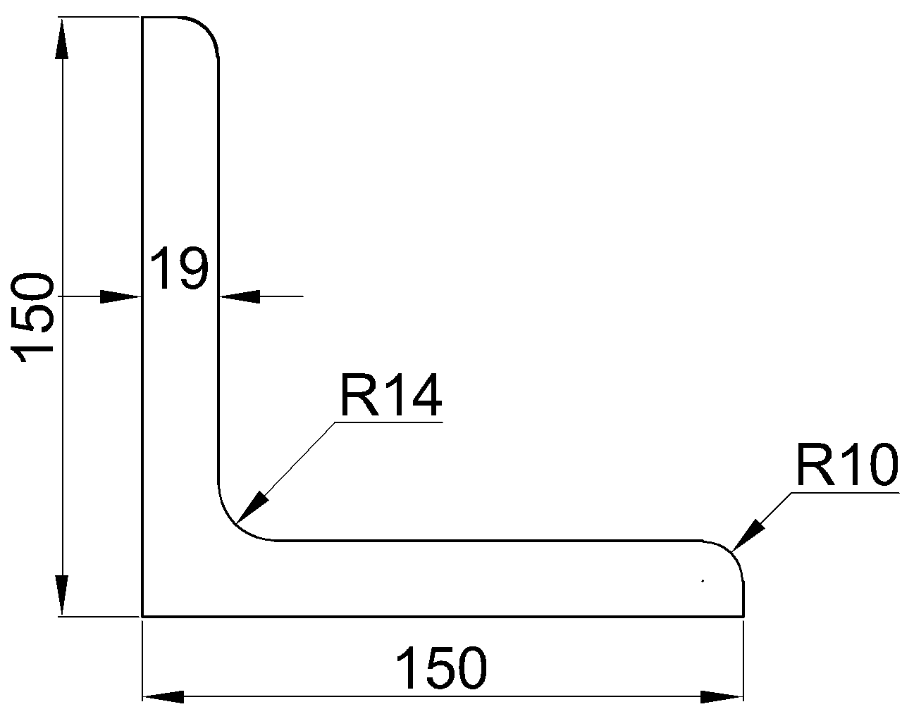
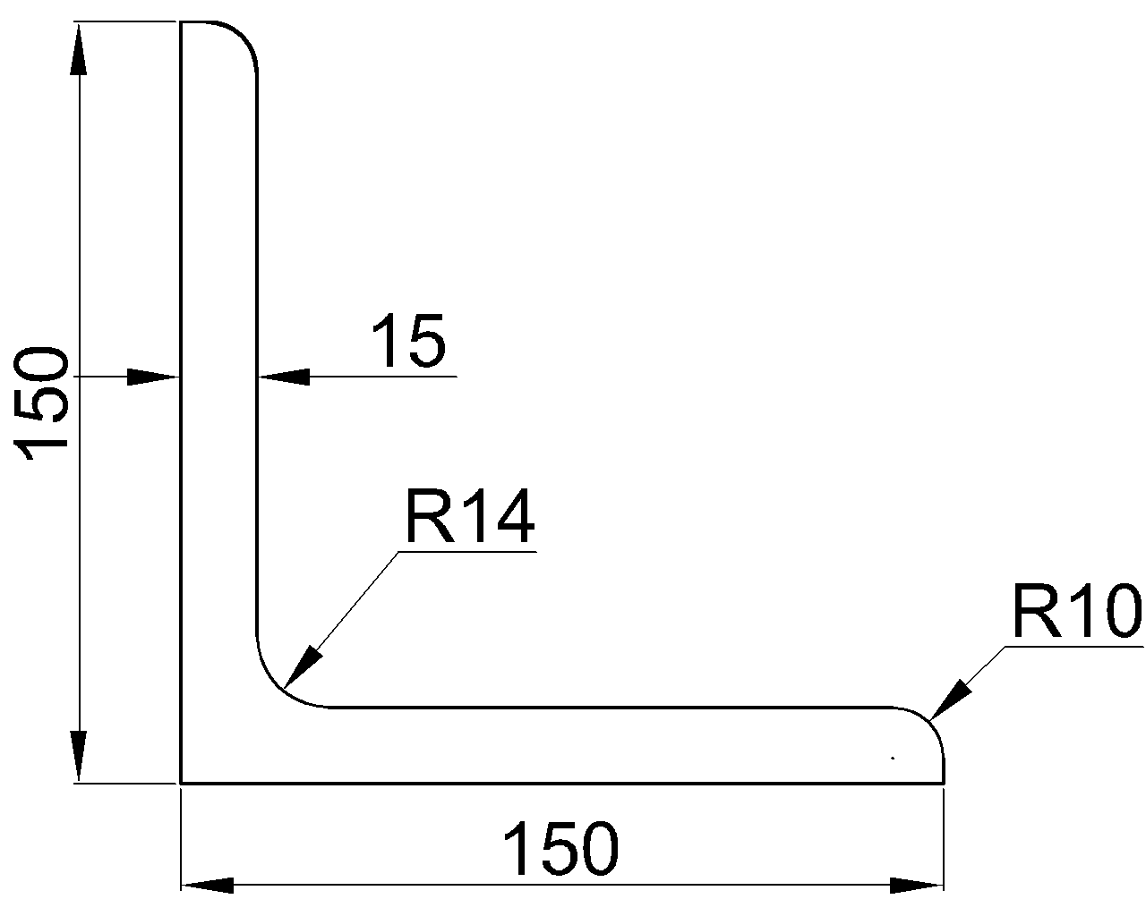
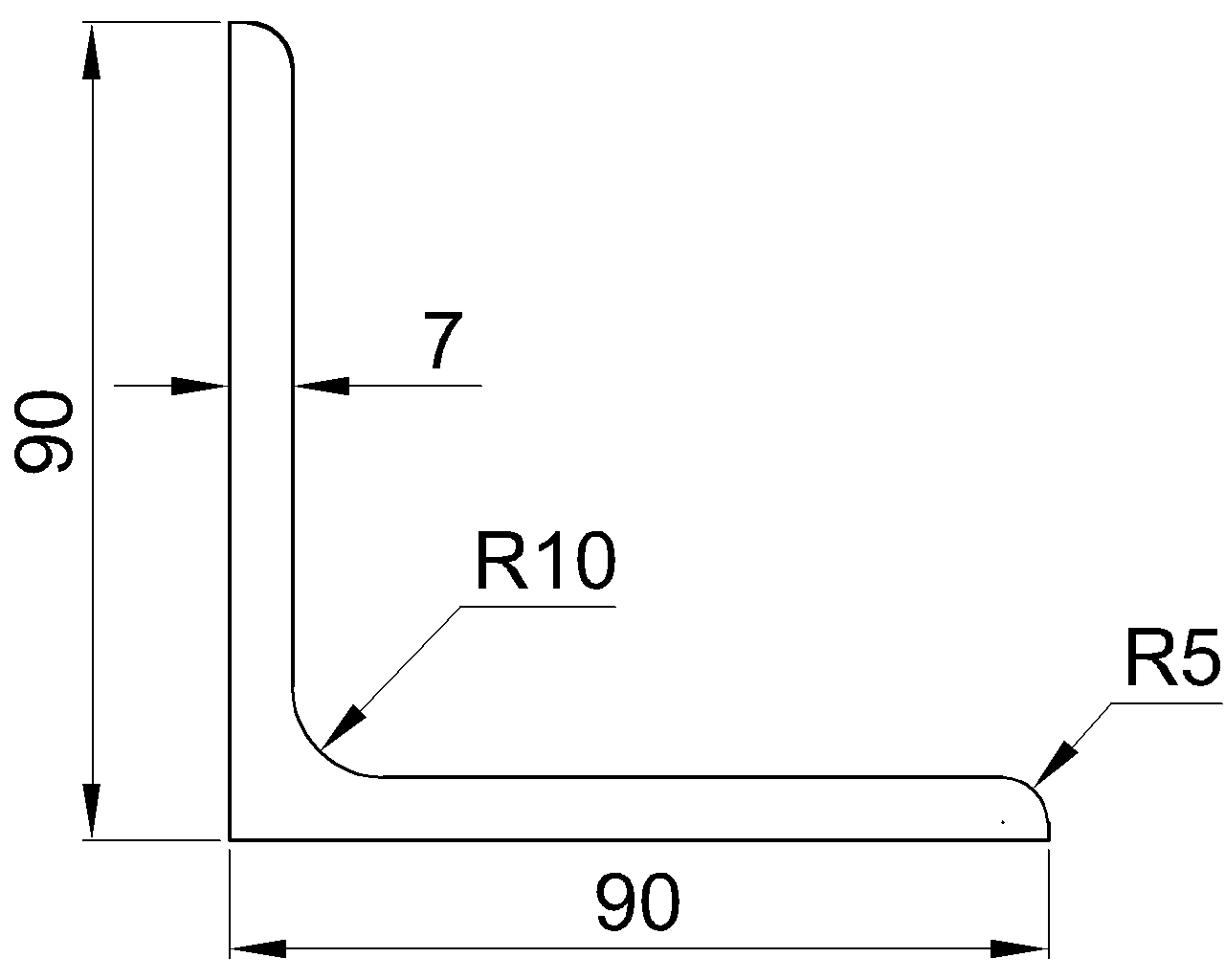
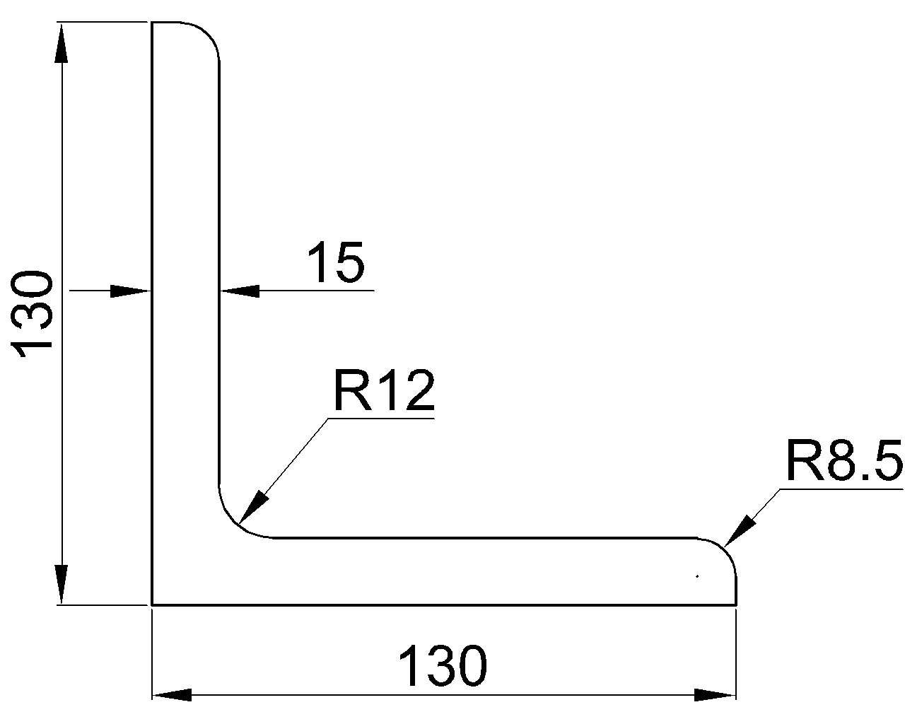
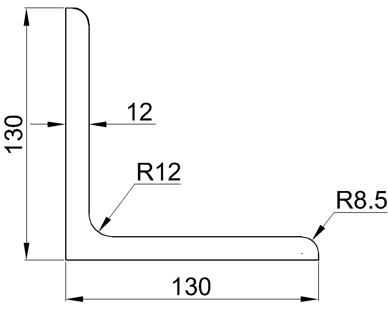
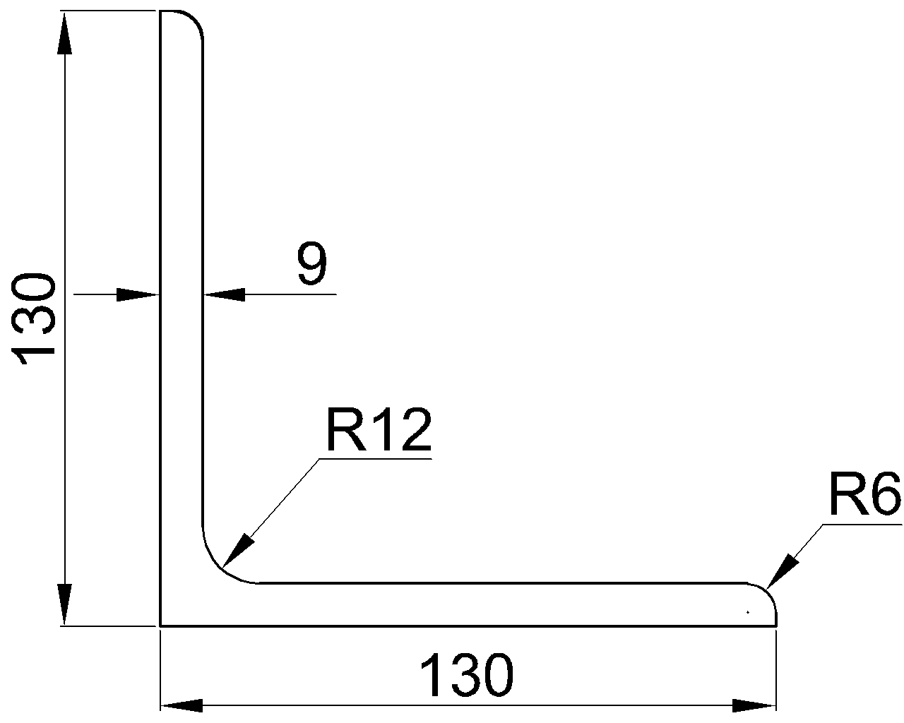
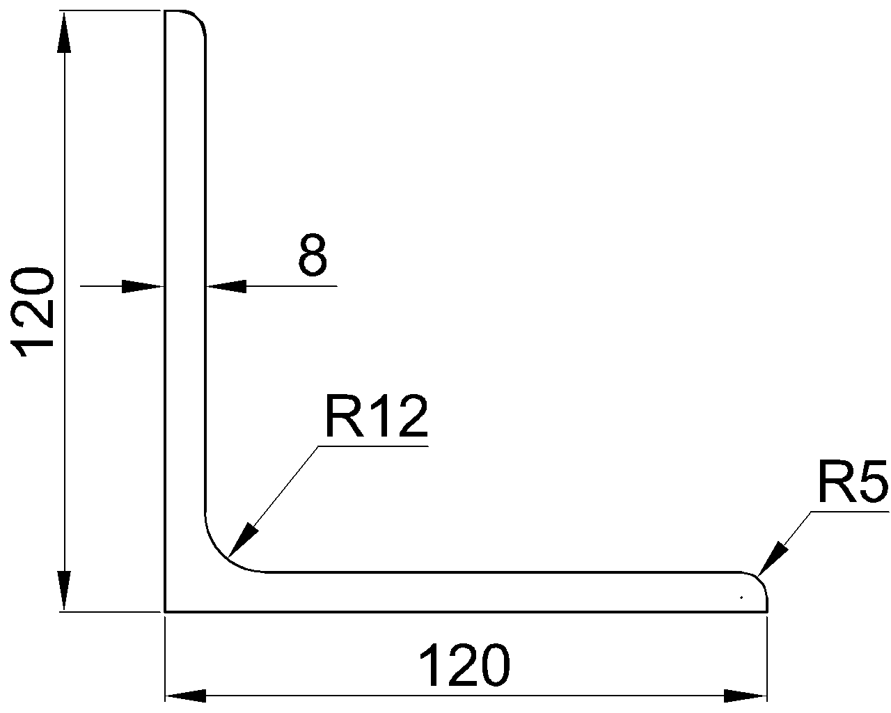
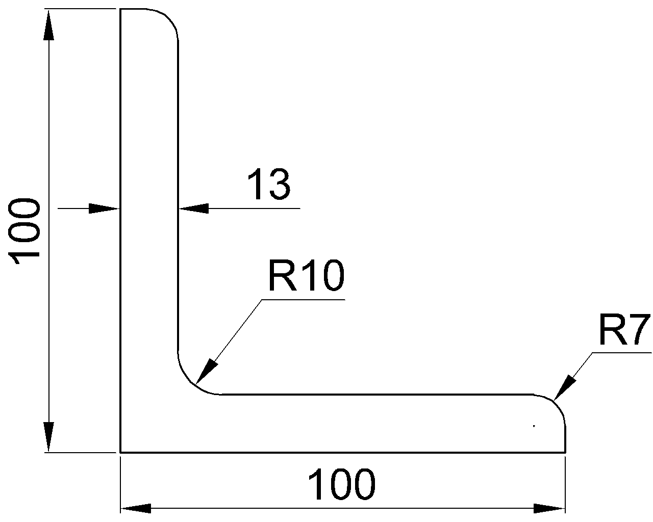
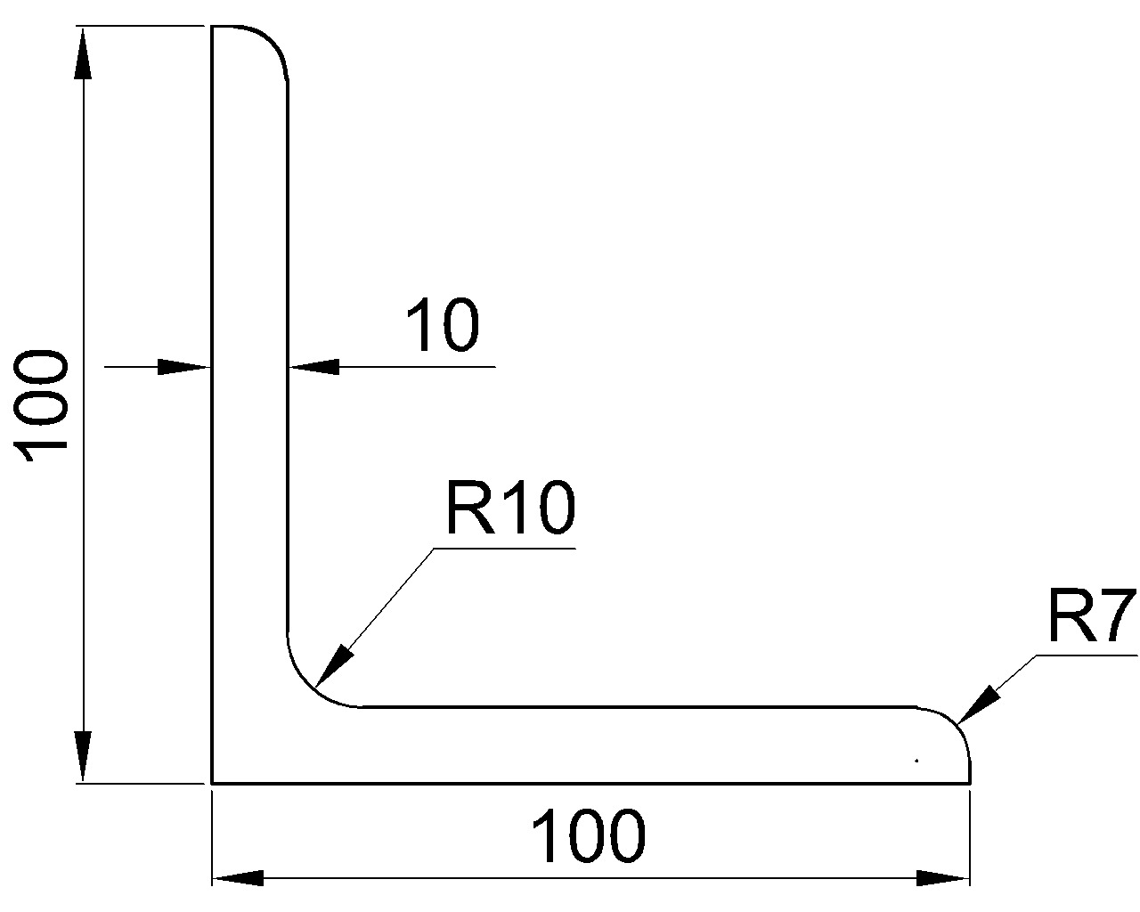
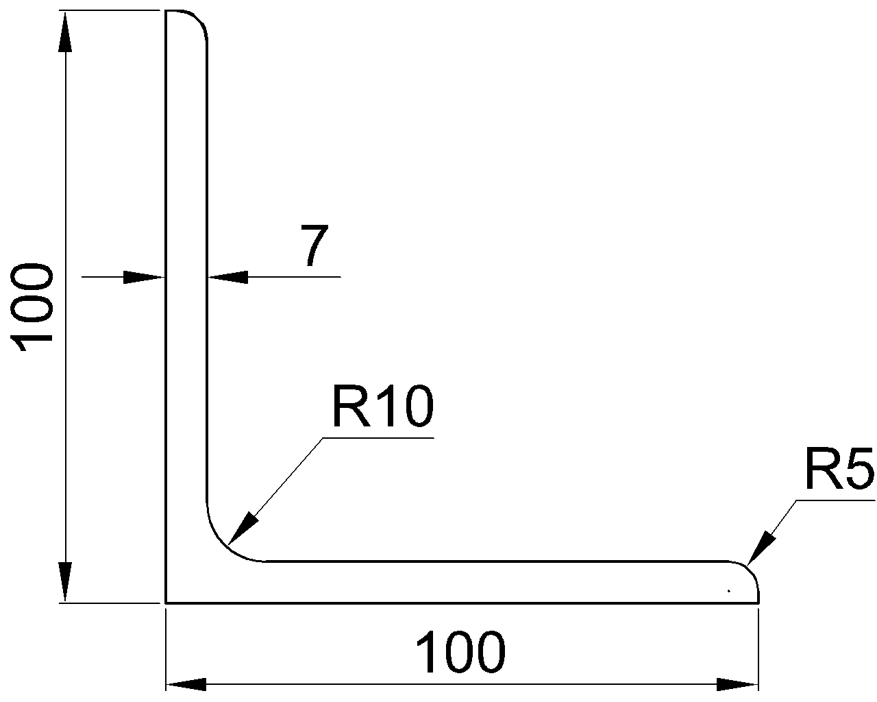
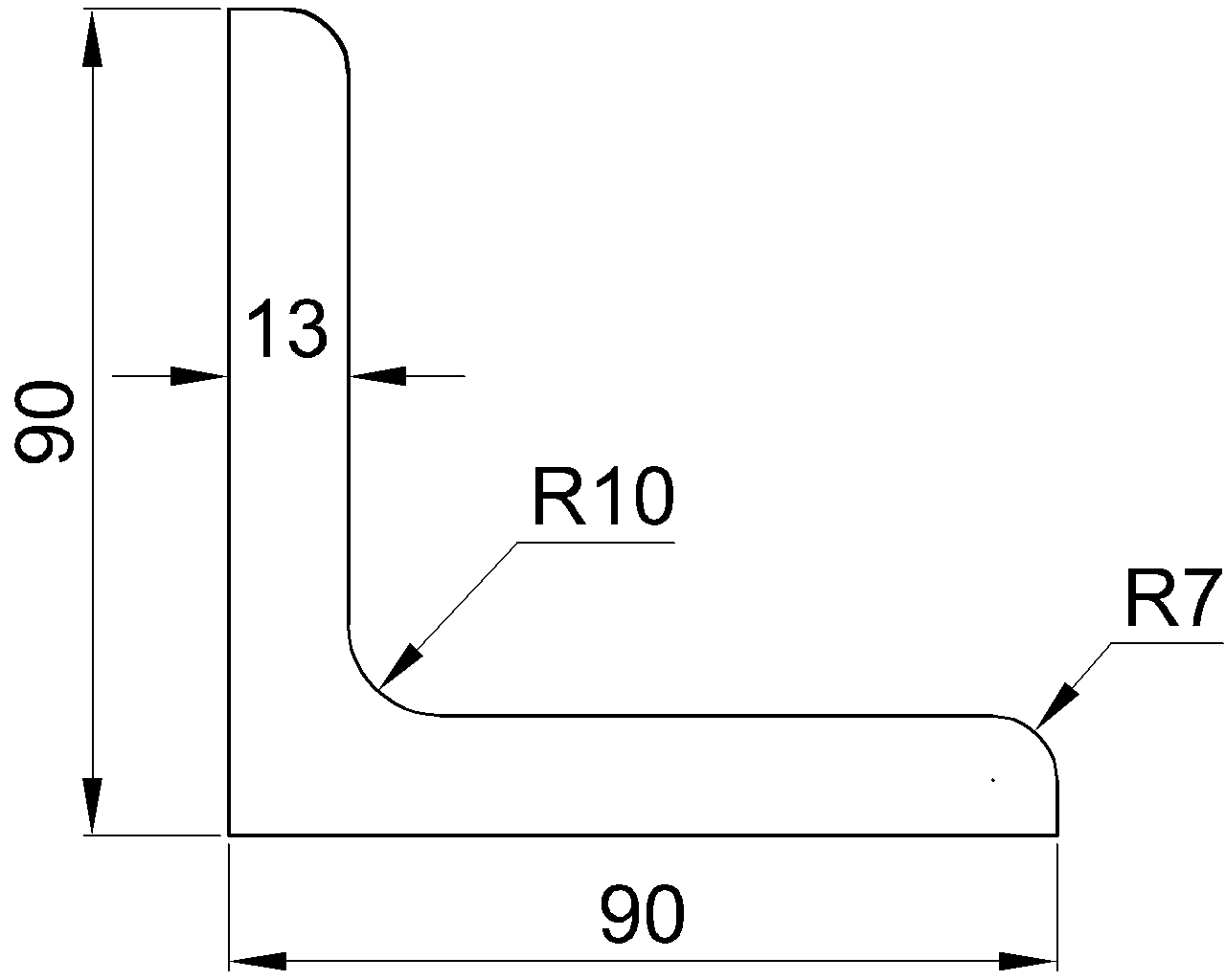
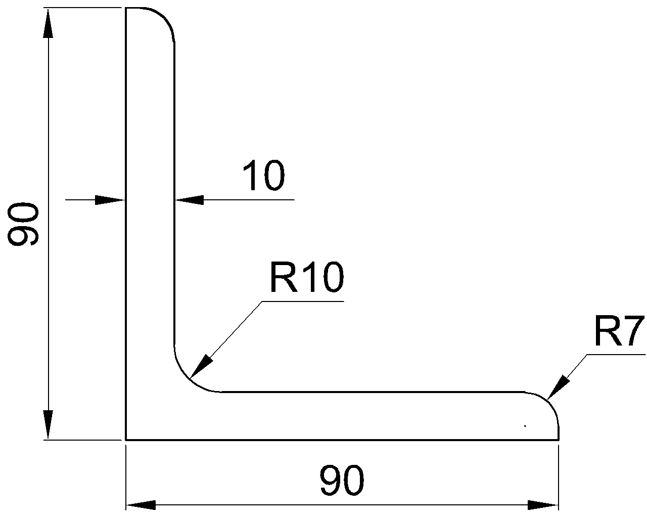
| Angles | A common leg thickness is typically used | The heel includes a root radius, so the inside corner is not square. |
| HSS | Wall thickness rather than separate web and flange thicknesses | Rounded corners and the applicable wall-thickness convention must be considered. |
| Built-up members | Individual plate thicknesses | Welds, plate offsets, gaps, and assembly tolerances are part of the actual geometry. |
Terminology should follow the shape family. Calling an HSS side a flange may be convenient in conversation, but it can create confusion in drawings, calculations, and data mapping. Likewise, the projecting element of a tee is more clearly called the stem than the web when communicating fabrication requirements.
Common CAD Modeling Errors
Drawing three sharp-cornered rectangles
A center web rectangle and two flange rectangles can be adequate for a schematic model, but the result should not be mistaken for fabrication-level geometry. This method omits the root fillets and may create false open space near the flange.
Offsetting from the wrong web face
Connection geometry is sometimes copied from one side of a member and mirrored without checking the local coordinate system. The centerline, near web face, far web face, and member work line are different references. Web thickness determines the separation between the web faces, but it does not identify which face controls the detail.
Assuming the nominal centerline is unchanged after substitution
When one shape is replaced by another, changes in depth, flange width, and thickness can move connection surfaces even if the analytical member line remains fixed. A flange-supported element may shift relative to the model centerline, while a web-connected plate may require a different gap or offset.
Using rounded display values as exact geometry
Imported schedules and software interfaces may display fewer decimal places than the underlying database. Avoid reconstructing a section from rounded screen values when a verified shape profile or authoritative data set is available. Unit conversion can introduce additional rounding differences.
Connection Detailing Uses for tw
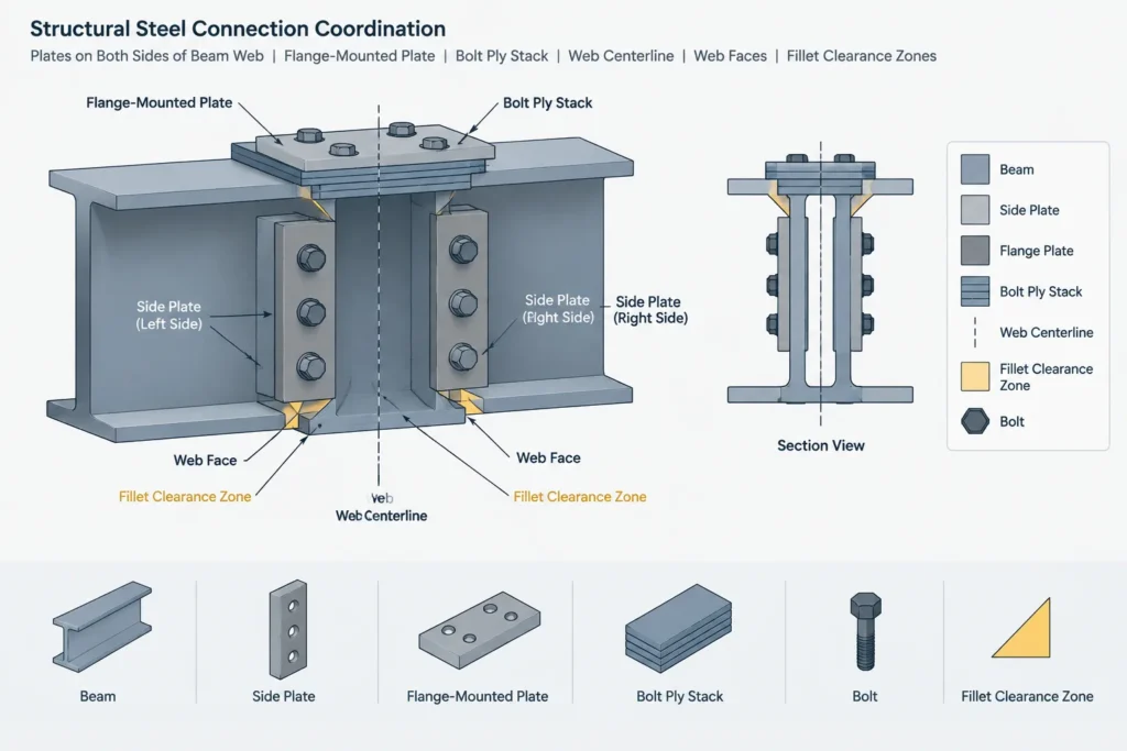
Web thickness is often needed to establish the location of connection material on opposite sides of a web. It also affects bolt grip when the web is included in a ply stack and can influence the gap between paired connection elements.
Typical coordination questions include:
- Are angles or plates attached to one side or both sides of the web?
- Are hole coordinates referenced to the web centerline or a web face?
- Does a shop-welded plate fit within the clear region between flange fillets?
- Does the bolt stack account for the actual connected plies?
- Will a stiffener fit against the web without an unintended gap or fillet clash?
These are geometric and detailing questions. Connection strength, weld sizing, local limit states, and member capacity require project-specific engineering checks beyond the thickness shown in a shape table.
Connection Detailing Uses for tf
Flange thickness affects the elevation or offset of components attached to a flange face. Examples include cap plates, flange splice plates, seats, deck-support elements, and framing attached near the top or bottom of a member.
A common mistake is to use overall section depth and flange thickness to infer every internal clearance. That approach ignores fillets and may overlook the difference between a nominal section dimension and a fit-up requirement. If a plate must sit close to the web-to-flange intersection, the rolled transition geometry must be considered explicitly.
Flange thickness also contributes to a bolted connection’s ply stack. The complete stack should include each connected part, relevant washers, and the selected fastening arrangement. The flange value alone does not determine bolt length or installation access.
A Reliable Shape-Data Workflow
- Confirm the full shape designation. Similar depth labels do not guarantee identical thicknesses or connection surfaces.
- Check units and field names. Verify that tw and tf have not been confused with wall thickness, leg thickness, or a detailing clearance.
- Identify the required level of geometry. Use simplified outlines for diagrams and verified detailed profiles for clearance-sensitive work.
- Establish the insertion point and orientation. Record whether the section is placed by centroid, web centerline, top of steel, or another datum.
- Check fillet-sensitive components. Review stiffeners, end plates, clip angles, welds, and holes near rolled corners.
- Recheck after revisions. A shape substitution can alter more than weight and depth; it can change all connected-face locations.
What to Show on Drawings
Shop and design drawings usually identify the member by its shape designation rather than dimensioning its web and flange thickness directly. Repeating catalog dimensions can clutter the drawing and create conflicts if the member is later revised.
Show thickness dimensions when they control fabricated components, unusual geometry, or inspection requirements. For standard rolled shapes, use the designation as the primary identifier and dimension the connection from stable, clearly named datums. Notes and details should distinguish between member centerlines, web faces, flange faces, and work points.
Key Takeaway
tw and tf are essential section dimensions, but they are not complete descriptions of a rolled steel profile. Web thickness does not define clear web depth, and flange thickness does not define fillets, flange width, or every connected-face location. Reliable detailing combines verified shape data with correct orientation, explicit datums, and an appropriate level of CAD geometry.