The warping constant, commonly shown as Cw in structural steel shape tables, is one of the least intuitive section properties. Area and moment of inertia can be related directly to axial or flexural behavior, but Cw describes a particular part of torsional response: the resistance associated with nonuniform longitudinal displacement, or warping, of the cross section.
Cw is especially relevant to open sections such as W-shapes, channels, structural tees, and some built-up members. It may appear in lateral-torsional buckling equations, torsional analysis, and software input data. It is not a general-purpose measure of torsional strength, and it should not be confused with the torsional constant J.
What does cross-section warping mean?
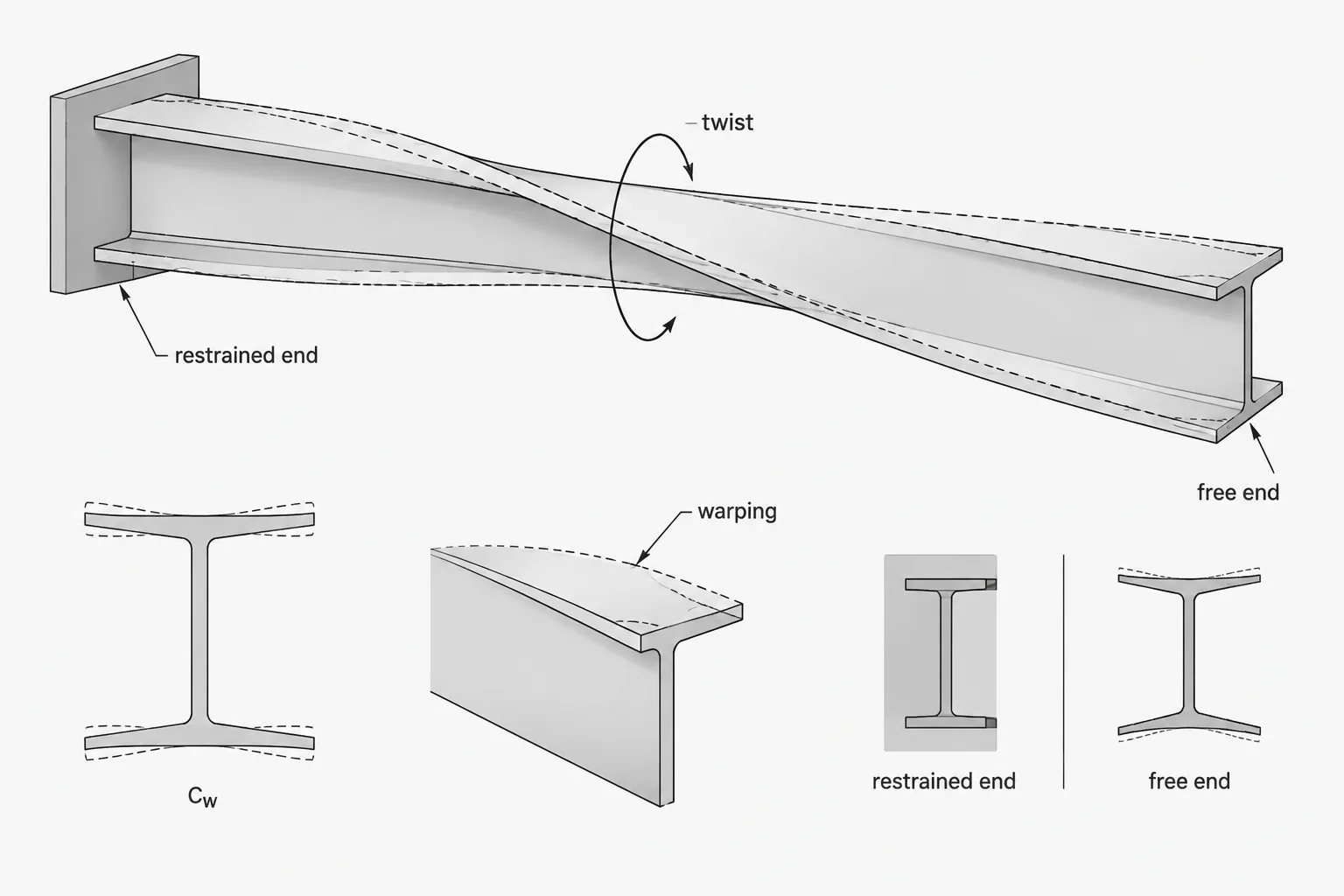
When a member twists, its cross section does not necessarily remain a perfectly flat plane. Different points on the section may tend to move longitudinally by different amounts. This out-of-plane displacement pattern is called warping.
An open I-shaped section provides a useful visualization. As the member twists, one flange tends to warp longitudinally in a pattern opposite to the other flange. If the member is free to develop that deformation, the torsional response differs from the case in which an end plate, diaphragm, connection, or adjacent framing restrains the flange movement.
The warping constant is a geometric property used to characterize resistance associated with this warping behavior. Its value depends strongly on how material is distributed around the section and, for open sections, how far key elements lie from the relevant section axes.
Cw and J describe different parts of torsional behavior
Cw and J are both listed among torsion-related section properties, but they are not interchangeable.
| Property | Common description | Typical dimensional form | What it helps represent |
|---|---|---|---|
| J | Torsional constant | Length to the fourth power | Saint-Venant, or uniform, torsional response |
| Cw | Warping constant | Length to the sixth power | Resistance associated with restrained or nonuniform warping |
| I | Area moment of inertia | Length to the fourth power | Flexural stiffness about a specified axis |
Saint-Venant torsion is the part of the response commonly associated with section twist and shear stress. Warping torsion introduces longitudinal stresses when the natural warping deformation is restrained or varies along the member length. A complete torsional analysis of an open section may need to account for both effects.
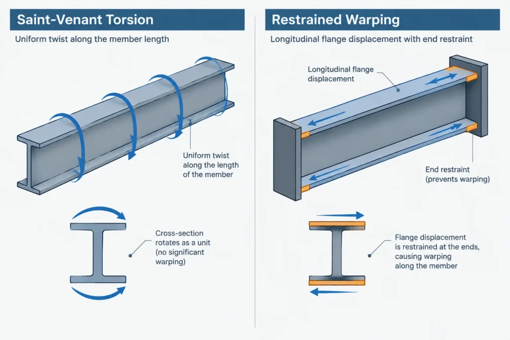
A large Cw does not automatically mean that a member is broadly “better in torsion.” Member length, boundary conditions, load position, shear-center location, J, material stiffness, bracing, and connection restraint can all influence the response.
Why W-shapes can have significant warping resistance
In a doubly symmetric W-shape, the flanges are separated by the web depth. During twisting, the two flanges participate in opposing longitudinal warping patterns. Flange size and flange separation therefore have an important influence on Cw.
This explains why two shapes with similar area or even similar J can have substantially different warping behavior. Increasing material close to the section center does not affect Cw in the same way as placing flange material farther from the appropriate axis.
Cw is also one reason torsional behavior cannot be inferred reliably from weight per foot or nominal depth alone. The complete distribution of material matters.
How channels, tees, and angles complicate the picture
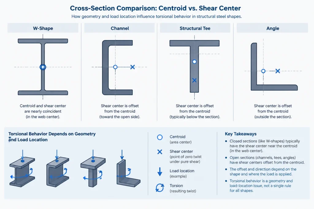
For singly symmetric or unsymmetric open sections, torsional behavior is tied closely to the shear center and principal section geometry. The centroid may not coincide with the shear center, so a load passing through the centroid can still create twist.
- Channels: The shear center generally lies outside the web centerline. Load application at the web or centroid may therefore introduce torsion.
- Structural tees: The flange-and-stem arrangement produces warping behavior different from that of the parent I-shape.
- Angles: Principal axes are rotated from the leg directions, and torsion, bending, and load eccentricity can interact.
- Built-up open sections: Cw depends on the actual connected geometry. It should not be obtained by casually adding the tabulated Cw values of individual components.
For these sections, the coordinate system and section orientation used by a table or analysis program must be understood before properties are transferred.
Where Cw appears in practical design work
Lateral-torsional buckling
When an unbraced beam bends about its major axis, the compression region may move laterally while the section twists. Elastic lateral-torsional buckling formulations commonly include both uniform torsional stiffness and warping-related stiffness. Cw is therefore an important input even when no separate torsional load is shown on the framing plan.
Members under applied torque
Open-section members supporting eccentric loads, projecting brackets, facade framing, equipment, or offset connections may be subjected to torque. If twist varies along the member or warping is restrained at supports, Cw can affect longitudinal stresses and twist distribution.
Analysis software and custom sections
Structural software may request Cw when defining a custom section. Leaving the field blank, entering zero, or substituting J can materially change the analytical model. The correct action depends on the software formulation and the section type, so the input definition should be checked rather than assumed.
Boundary conditions determine whether warping resistance is mobilized
Cw is a section property, but the stresses associated with warping depend on member-level restraint. A cross section may tend to warp freely at an unrestrained end while experiencing partial or substantial restraint near a rigid diaphragm, end plate, or connection.
Real connections are rarely described perfectly by the simple labels “free” and “fixed.” Their behavior can depend on flange continuity, plate stiffness, weld arrangement, connected member stiffness, and whether the detail can transfer the longitudinal force pattern associated with warping.
A drawing should not imply full warping restraint merely because a beam end appears visually enclosed. Conversely, a connection may introduce meaningful restraint even if it was not intentionally designed as a torsional support. The assumed analytical boundary condition should be coordinated with the physical detail.
Unit conversion requires special care
Cw has dimensions of length to the sixth power. This makes unit mistakes unusually severe because the linear conversion factor must be raised to the sixth power. A direct value copied between imperial and metric models without conversion can be wrong by many orders of magnitude.
A reliable workflow is to:
- identify the units stated by the source table;
- confirm whether the software expects the same unit system;
- convert the linear unit using a sixth-power factor;
- retain enough precision during the conversion;
- compare the result with a verified value for the same shape and orientation.
Do not infer the units solely from the magnitude displayed in a software dialog or spreadsheet column.
Why CAD geometry may not reproduce a tabulated Cw
Calculating Cw from a section outline is more specialized than calculating area, centroid, or moment of inertia. Basic CAD region tools often do not report warping properties at all. Engineering applications that do calculate Cw may use centerline thin-wall models, idealized sharp corners, mesh-based section analysis, or detailed rolled profiles.
Differences may result from:
- omitted rolled fillets or corner geometry;
- simplified flange and web outlines;
- thin-wall assumptions;
- incorrect section connectivity;
- axis or origin definitions;
- mesh density and numerical method;
- using nominal rather than verified shape dimensions.
A visually accurate CAD profile is not, by itself, proof that the computed Cw matches an authoritative shape-table value.
A practical verification checklist
- Confirm that the designation, shape family, and data source match the member being analyzed.
- Check whether Cw is reported and whether a blank entry means unavailable rather than zero.
- Verify the units explicitly, including the sixth-power exponent.
- Keep Cw separate from J, I, S, and polar moment terminology.
- Confirm section orientation and axis conventions for channels, tees, angles, and custom sections.
- Review how the analysis model treats torsion, warping, bracing, and end restraint.
- For built-up members, use a method that represents the assembled geometry and actual connectivity.
- Investigate major differences between calculated and published values instead of selecting whichever value appears more convenient.
Key takeaway
The warping constant Cw is a geometric property that helps describe the warping component of torsional behavior. It is particularly important for open steel sections and in problems involving lateral-torsional buckling, nonuniform torsion, or restrained member ends. It does not replace J, and it does not establish torsional capacity on its own. Correct use requires verified section data, careful unit handling, appropriate axes, and boundary conditions that reflect the actual connection and bracing details.