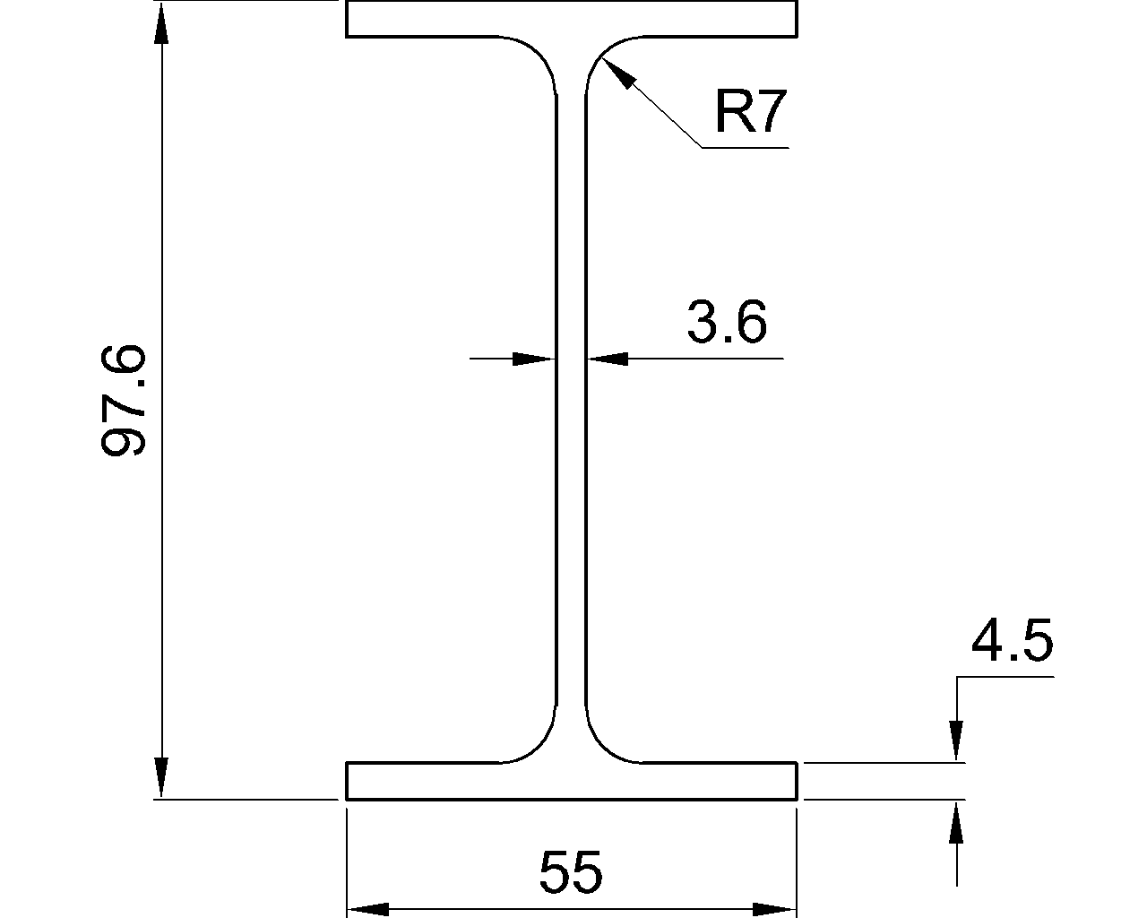
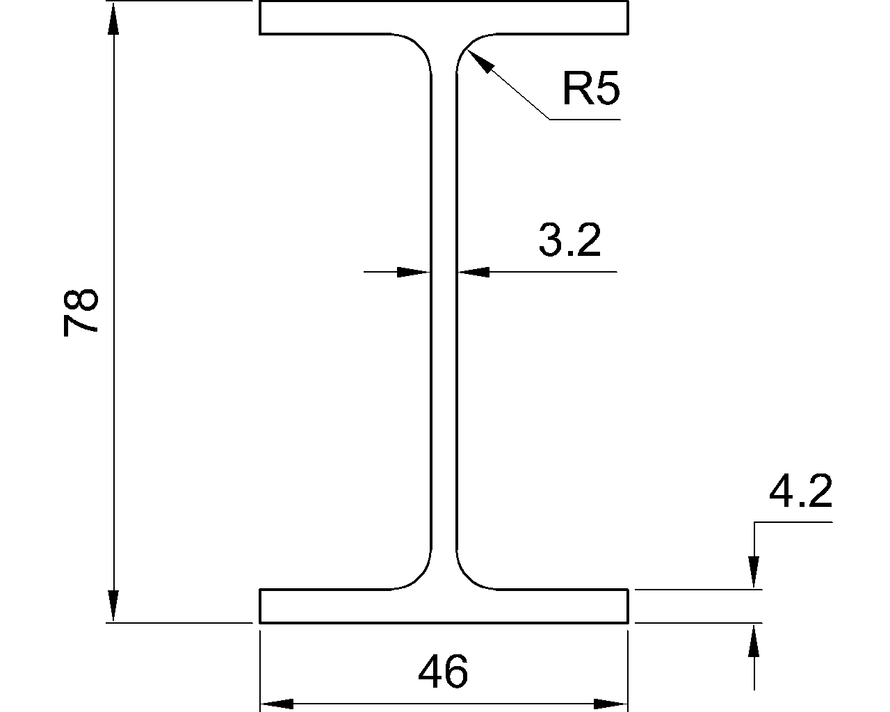
The W21x50 is a W-shaped structural steel section reference for engineers, detailers, fabricators, and students working with steel framing information. This page preserves the source dimensions and section data while adding practical context for reading the listing and using the companion CAD file.
Use the values below as a reference for identifying the section geometry and mass basis. Design, connection detailing, fabrication, and erection decisions require the applicable project requirements and verification by a qualified engineer.
W Beam
refer to : AISC 16
the American Institute of Steel Construction (AISC) Specification for Structural Steel Buildings (AISC 360-16), which is the 2016 edition of the AISC Specification for Structural Steel Buildings. It provides guidelines and requirements for the design, fabrication, and erection of steel structures in the United States.
Depth : 528.3 mm
Width : 165.9 mm
Web Thickness : 9.7 mm
Flange Thickness : 13.6 mm
Root Fillet Radius : 12.8 mm
Sectional Area : 94.84 cm2
Unit Weight : 74.4 kg/m
How to read the W21x50 reference
The listing identifies the overall depth and width of the section, together with web thickness, flange thickness, and root fillet radius. These dimensions describe the rolled shape and are useful when checking clearances, modeling the profile, preparing details, or comparing a section against project requirements.
Sectional area and unit weight
Sectional area describes the steel area through a cross-section of the member. Unit weight expresses the mass of the section per unit length. Together, these values support material takeoffs, shipping estimates, framing coordination, and other preliminary reference tasks. They do not by themselves establish allowable strength, deflection performance, connection capacity, or suitability for a specific structural design.
AISC reference context
The source identifies AISC 360-16 as the governing specification reference. Readers should distinguish between a shape-dimension listing and the broader requirements that may apply to material specification, analysis, design, fabrication, erection, and inspection. For related background, see the site’s guides to W-shapes, steel section properties, and AISC terminology.
Using the DWG resource
The downloadable DWG file can help with drafting and coordination workflows. Before incorporating it into a production drawing, verify units, scale, layer conventions, insertion point, and the profile against the authoritative dimensions shown on this page. Keep CAD geometry separate from engineering checks and project-specific design decisions.
Frequently asked questions
What type of section is the W21x50?
It is listed as a W Beam, commonly used as a reference designation for a wide-flange structural steel shape. The exact geometry for this entry is given by the source dimensions on the page.
What information is provided for the W21x50?
The reference provides depth, width, web thickness, flange thickness, root fillet radius, sectional area, and unit weight. It also identifies the AISC reference and provides a DWG download resource.
Can the listed unit weight be used for a final material estimate?
It can support preliminary quantity and mass calculations, but final estimates should account for the project scope, member lengths, connections, plates, detailing assumptions, coatings, fabrication allowances, and other specified materials.
Does the DWG file replace structural design checks?
No. A CAD file represents drafting geometry. It does not establish member strength, stability, serviceability, connection capacity, or compliance with project-specific requirements.