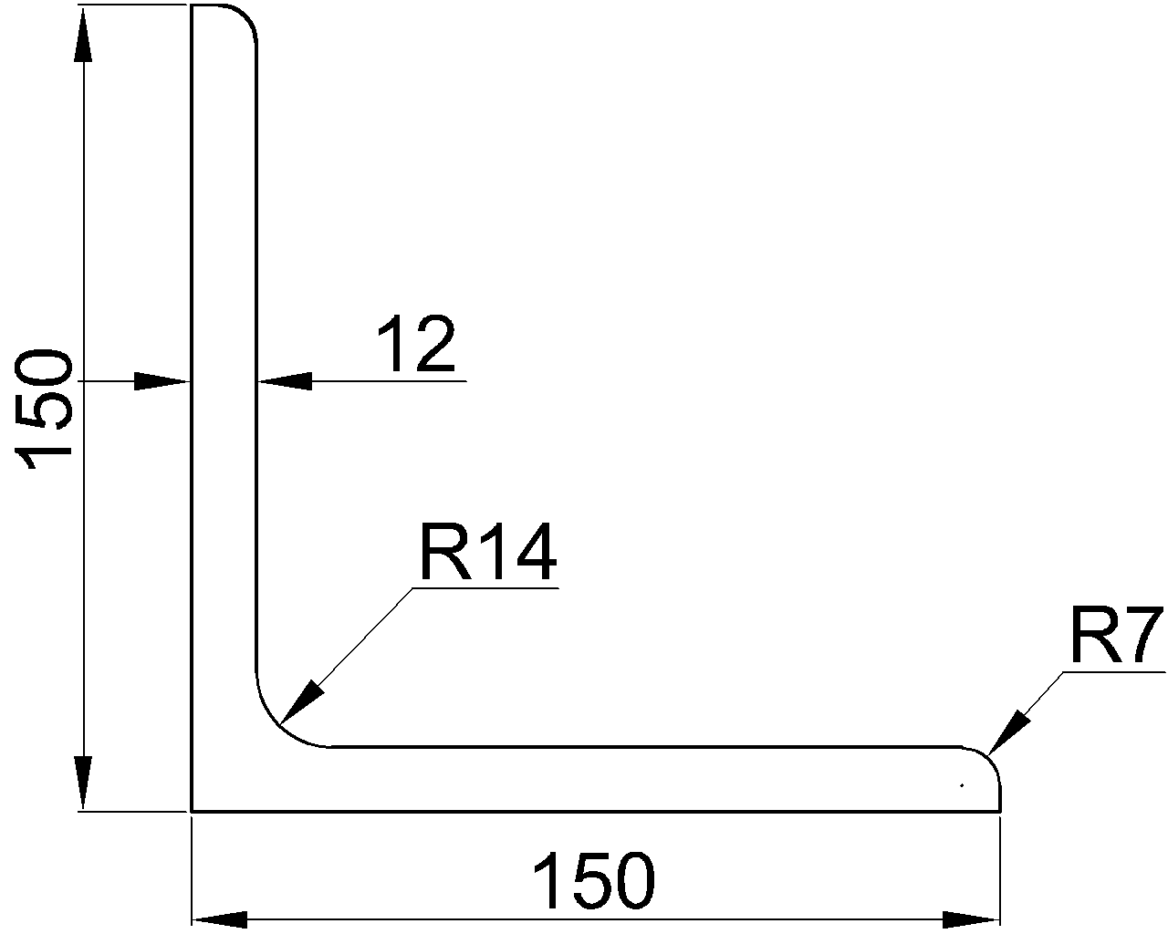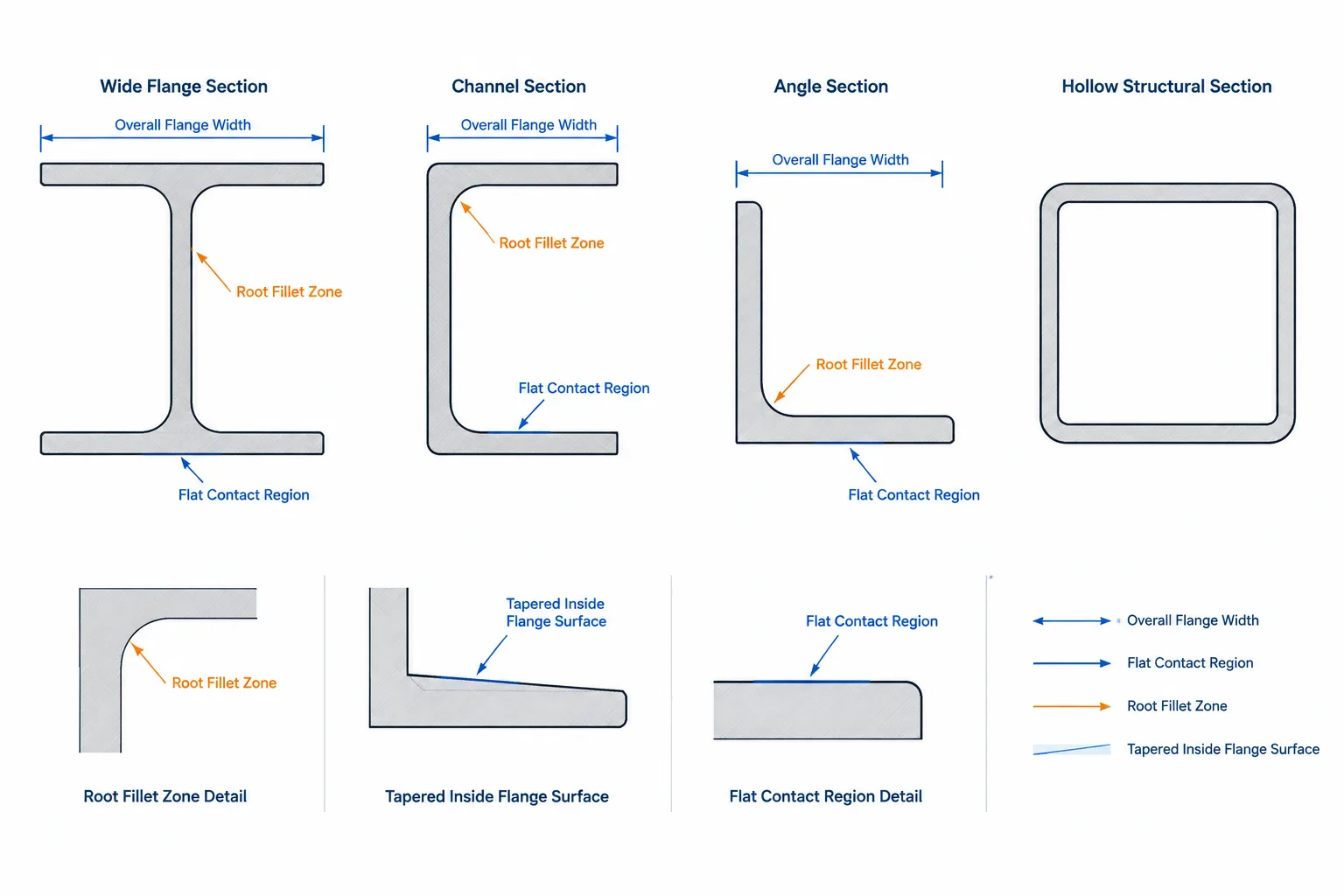
A shape table may list the overall flange width of a rolled steel section, but that dimension does not describe the entire surface available for a plate, washer, bolt head, weld, or other connection component. Root fillets, rounded edges, flange taper, rolling variation, and the orientation of the connected part can all reduce the area that provides practical contact.
This distinction matters when detailing W shapes, S shapes, channels, HP shapes, and other rolled sections. A connection can fit inside the nominal flange width while still interfering with a fillet, rocking on a sloped surface, or extending beyond an edge. The appropriate question is therefore not only, “How wide is the flange?” but also, “Which portion of that flange provides the contact condition required by this detail?”
Overall flange width is a bounding dimension
Overall flange width, commonly identified by a symbol such as bf, measures from one flange edge to the other. It is useful for establishing the section envelope, checking clashes, locating member centerlines, and comparing shape sizes. It should not automatically be treated as the width of a perfectly flat rectangular surface.
Rolled sections contain geometric transitions that are necessary to their manufacture. Where a flange meets a web, a root fillet replaces the theoretical sharp corner. Flange tips may also have rounded or non-square edges. On some shape families, the inside flange surfaces are sloped rather than parallel to the outside surfaces.
As a result, several different widths may be relevant:
- Overall flange width: the full edge-to-edge dimension shown in the shape data.
- Clear width between root regions: the space outside the web and fillet zones, considered separately on each side of the web.
- Flat bearing width: the portion that can provide the required contact for a plate, washer, bolt head, nut, or seat.
- Available detailing width: the width remaining after edge clearances, hole locations, weld access, tolerances, and installation needs are considered.
These widths are related, but they are not interchangeable.
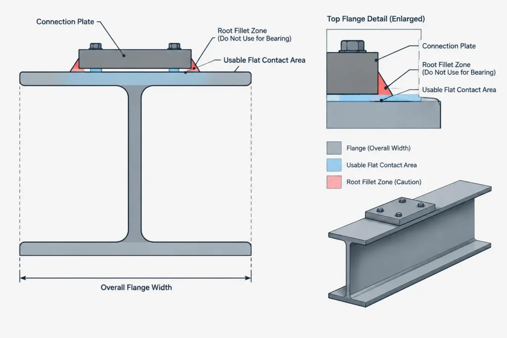
How rolled-shape geometry changes the contact surface
Root fillets at web-to-flange intersections
The root fillet occupies space near the web and prevents a square-edged plate from seating tightly against both the web and flange. This commonly affects flange connection plates, stiffeners, clip components, cap details, and fitted plates.
A simplified CAD profile drawn with sharp web-to-flange corners hides this interference. Even a profile that includes a nominal fillet should be treated carefully because the tabulated and detailing dimensions may describe different geometric limits. When fit depends on this area, use the appropriate published detailing information and provide a deliberate corner treatment, clearance, or fitted geometry as required by the project.
Parallel and tapered flange surfaces
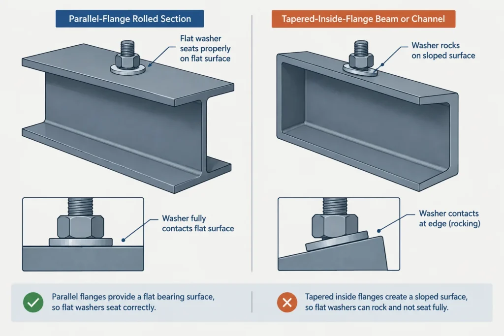
Many wide-flange and HP sections are represented with generally parallel flange faces, although their root fillets and rolled edges still affect contact. American Standard beams and channels characteristically have sloped inside flange surfaces. Other channel families and special sections must be checked individually rather than classified by appearance alone.
A component placed on a tapered inside flange surface may not bear uniformly if its contacting face is flat. A bolt head, nut, or ordinary flat washer can sit at an angle relative to the bolt axis. Connection details may therefore require a compatible seating arrangement, but the necessary solution must be selected and verified for the actual connection rather than assumed from a generic drawing.
Rolled flange edges
The edge of a rolled flange should not be modeled as though it were a precision-machined square corner unless the fabrication specifically creates that condition. Edge rounding and normal rolling variation can affect small edge-sensitive details. A plate or washer placed too close to the flange tip may not receive full support even when its theoretical outline remains inside the nominal flange boundary.
Shape-family considerations
| Shape family | Geometry to review | Typical detailing concern |
|---|---|---|
| W shapes | Root fillets, flange edges, and actual flange width | Fitted plates and hardware may conflict with fillet zones or lack full edge support |
| HP shapes | Heavy web-to-flange transitions and flange contact zones | Attachments near the web require explicit clearance checks |
| S shapes | Sloped inside flange surfaces | Flat hardware or plates may not seat uniformly |
| C channels | Inside flange slope, root transitions, and unequal access from the open side | Bolt seating and connected-angle alignment can be sensitive to orientation |
| MC and other channels | Family-specific flange geometry | Do not assume the same slope or proportions as a C channel |
This table is a geometry checklist, not a connection-selection guide. Shape availability and published dimensions should be confirmed from a reliable source appropriate to the project.
Connection components affected by usable flange width
Usable flat width can influence more than bolt-hole placement. The complete contact footprint should be reviewed for:
- bolt heads, nuts, and washers;
- flange splice plates and cover plates;
- stiffeners fitted near a web-to-flange intersection;
- beam seats and bearing components;
- column cap plates and attachments bearing on flange tips;
- welded plates requiring access along an edge;
- temporary erection hardware and installation tools; and
- components located on the inside face of a channel or tapered-flange section.
A hole center may satisfy the intended layout while the washer footprint overlaps a fillet or flange edge. Similarly, a plate outline may clear the overall section envelope but fail to seat because its corner enters the rolled root radius. Checking only centerlines is therefore insufficient.
A practical CAD checking workflow
1. Identify the controlling contact face
Determine whether the component bears against the outside flange face, inside flange face, web, or a combination of surfaces. This establishes whether flange slope, root fillets, or both are relevant.
2. Use an appropriate section profile
Insert verified shape data using consistent units. A simplified profile may be adequate for general arrangement drawings, but connection fit should be checked with geometry that represents the important fillets, slopes, and edges. Avoid tracing a small raster image or scaling an unverified block to match one overall dimension.
3. Draw the complete component footprint
Show the actual outline of the plate, washer, nut, bolt head, or seating component rather than checking only its insertion point. For a bolt, include the hardware footprint on the relevant face and account for its orientation relative to any flange slope.
4. Create no-contact or caution zones
Use construction geometry to identify root regions, rolled edges, and other areas that should not be treated as guaranteed flat bearing surfaces. Keep these guides on a non-plotting or clearly identified checking layer so they do not become fabrication lines.
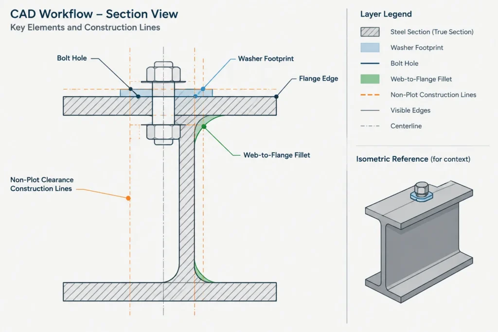
5. Check the section in the correct view
A plan or elevation may conceal interference that is obvious in a true section through the connection. For skewed or sloped members, inspect the geometry in a view normal to the contact plane. Projected views can make clearances appear larger than they are.
6. Allow for real fabrication conditions
Nominal CAD geometry does not eliminate mill variation, fabrication tolerance, coating thickness, weld profiles, or field fit-up needs. Where contact or clearance is critical, coordinate the intended fabrication method and show the controlling requirements clearly rather than relying on an exact graphical fit.
Common detailing mistakes
- Subtracting web thickness from flange width and calling the remainder usable: this ignores the root transitions and divides the space incorrectly for many applications.
- Using a sharp-corner section block: the resulting plate may occupy space that does not physically exist.
- Assuming every I-shaped section has parallel flange faces: shape-family geometry must be checked.
- Checking the hole but not the hardware: a valid hole location does not guarantee washer, nut, bolt-head, or wrench clearance.
- Dimensioning to a fillet tangent without a reliable definition: tangent locations may not be appropriate fabrication datums and can be difficult to inspect.
- Treating flange edges as machined surfaces: rolled edges do not provide the same geometric certainty as prepared contact faces.
What should be shown on the drawing?
Drawings should communicate the dimensions and preparation that control fabrication. Locate holes and parts from stable datums such as member centerlines, flange faces, web faces, or defined work lines. If a plate requires clipped corners, edge preparation, a fitted profile, or a special seating component, show that intent directly rather than expecting the shop to infer it from a nominal shape outline.
Avoid dimensioning a generic “usable width” unless it has a precise project-specific meaning. In most cases, it is clearer to dimension the component and its location, identify required clearances or preparations, and let verified section geometry support the fit check.
Key takeaway
Overall flange width describes the section envelope; it does not guarantee an equally wide, flat connection surface. Root fillets, flange taper, rolled edges, hardware footprints, and fabrication variation all influence usable flat width on steel flanges. Reliable detailing requires checking the actual contact face, using suitable shape geometry, and coordinating the complete connection component rather than relying on a single table dimension.