This page provides a dimensional and CAD reference for the UB 920x420x787 universal beam. The source information below identifies the governing dimensional reference and lists the section depth, width, web thickness, flange thickness, root radius, sectional area, and unit weight.
Use the listed fields when checking a section schedule, interpreting the beam designation, or preparing a preliminary drawing. The designation should not be treated as a substitute for the published dimensions because designation components and actual geometry may not be identical.
UB 920x420x787
Universal Beams
refer to : EN 10365:2017
a European standard that defines the dimensions, tolerances, and sectional properties for hot-rolled steel channels, I-beams, and H-beams used in construction and engineering. It ensures uniformity and compatibility across European structural steel products.
Dimension : 1011x437x40.9×73.9
Depth : 1011 mm
Width : 437 mm
Web Thickness : 40.9 mm
Flange Thickness : 73.9 mm
Root Fillet Radius : 19 mm
Sectional Area : 1002 cm2
Unit Weight : 786.6 kg/m
How to read this universal beam reference
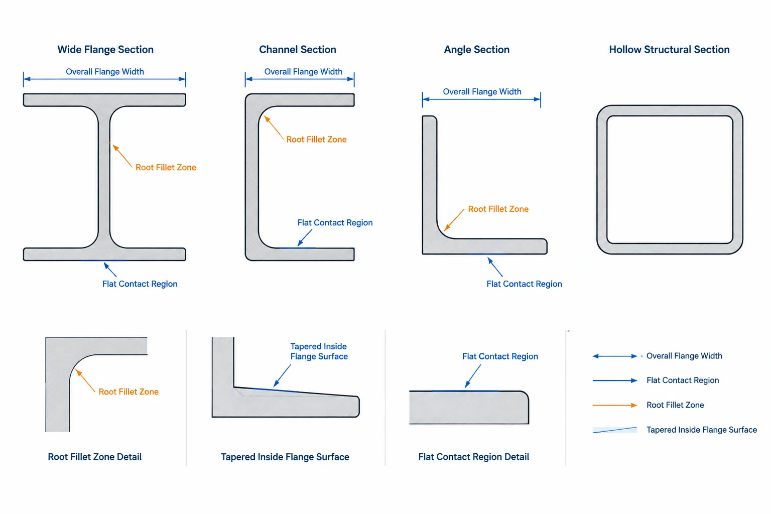
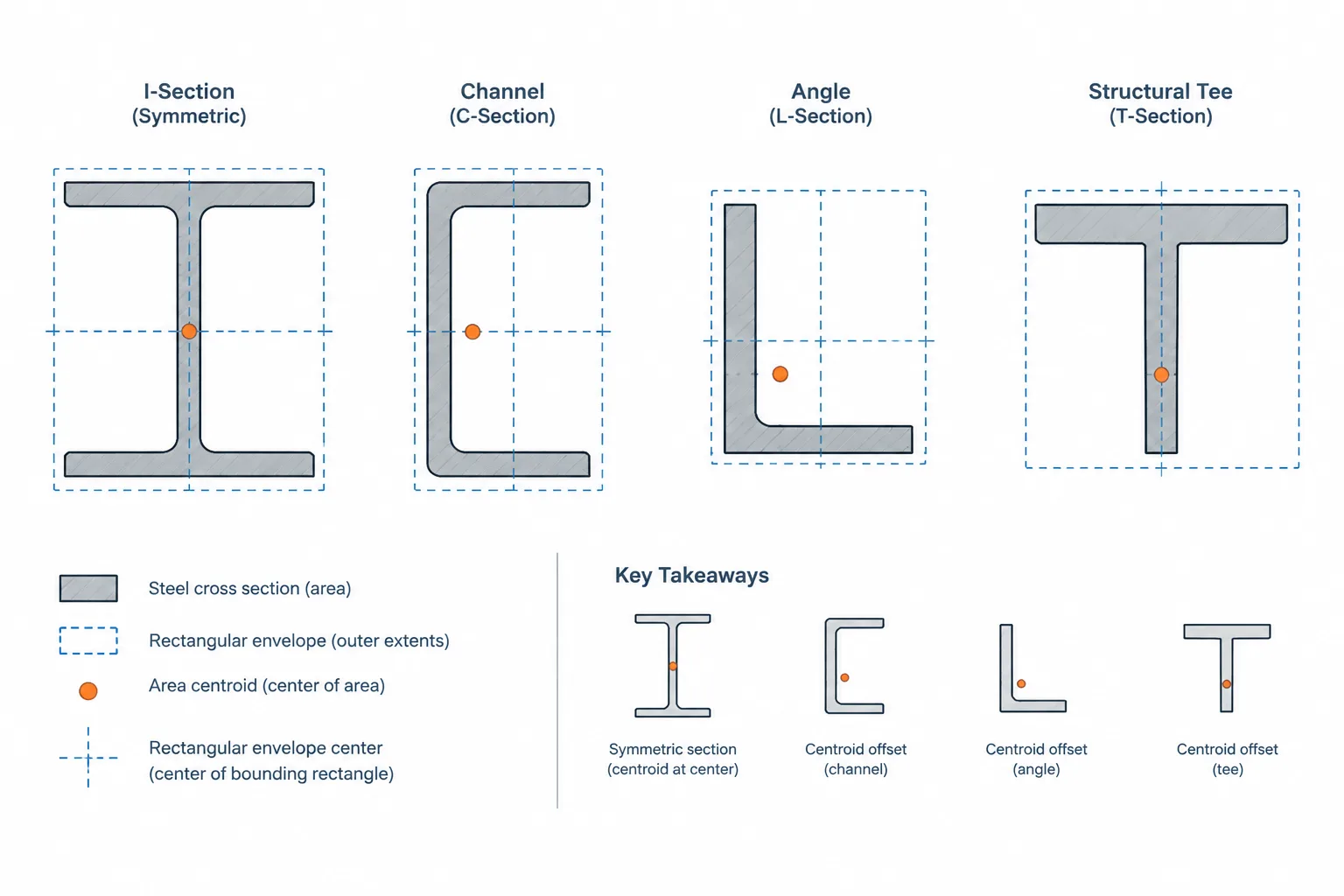
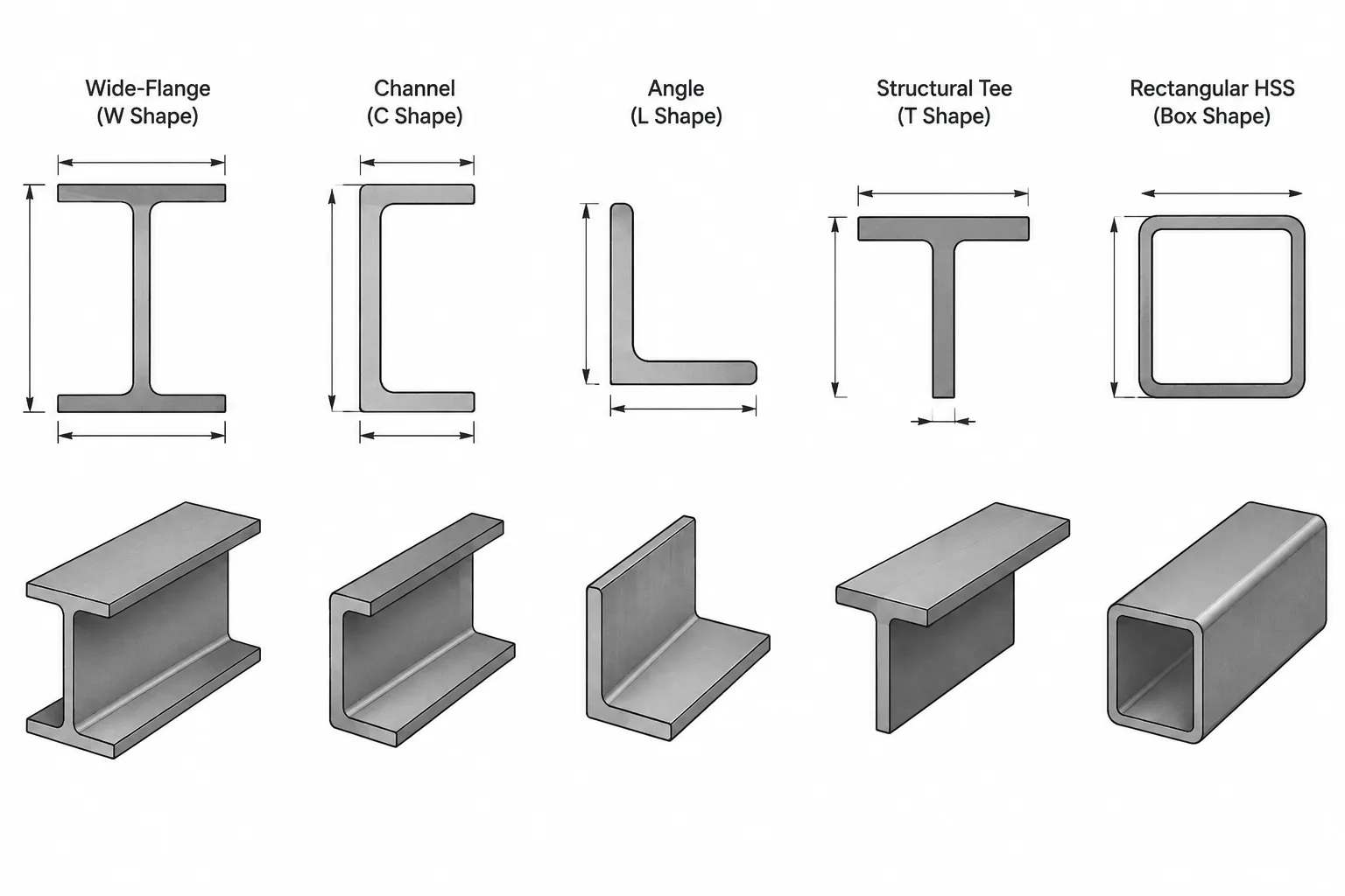
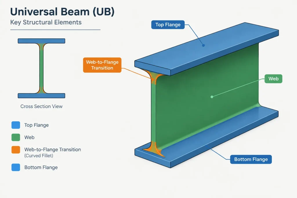
A universal beam is an open, doubly symmetric I-shaped section with two flanges connected by a web. Depth and width describe the overall envelope. Web thickness applies to the central plate-like portion, while flange thickness applies to the projecting elements at the top and bottom of the section.
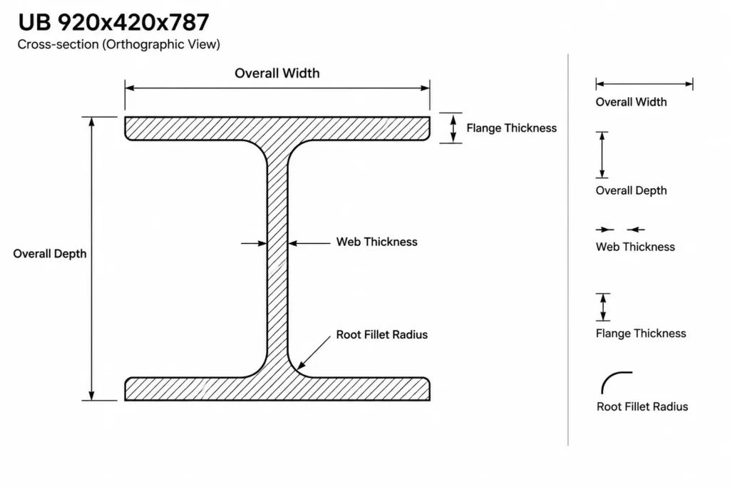
The root fillet radius describes the curved transition between the web and each flange. This radius matters in CAD modeling, clearance checks, connection detailing, cope layouts, and any condition where another component approaches the inside face of a flange.
Section area and unit weight
Sectional area represents the total cross-sectional area of steel. It is distinct from the section properties used for bending, shear, deflection, or stability calculations. Those additional properties should be obtained from an appropriate verified section database or project design source when required.
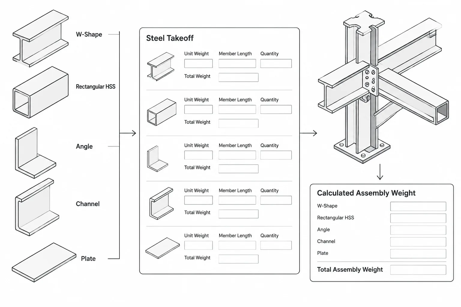
The listed unit weight is expressed as mass per unit length. It is useful for material takeoffs, member schedules, shipping estimates, and model coordination. Total member mass also depends on the selected cut length and any attached plates, stiffeners, connection material, or other fabrication items.
Using the DWG in a detailing workflow
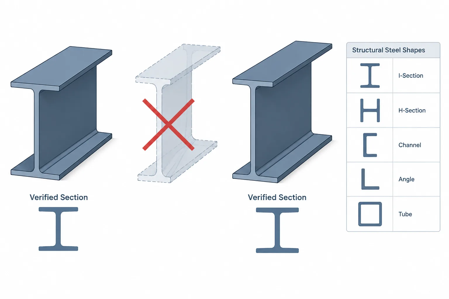
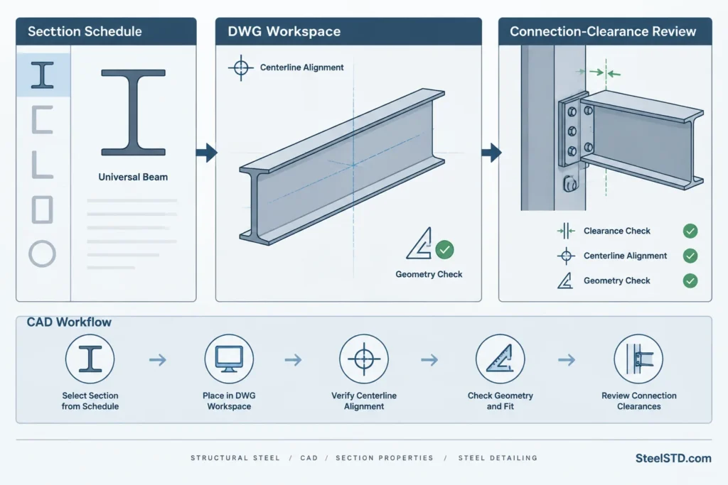
- Confirm the section identity: Match the drawing name and designation to the structural schedule before inserting it into a project file.
- Check drawing units: Verify the DWG insertion units and the units used by the host model. Do not rely only on how large the profile appears on screen.
- Verify critical geometry: Compare the CAD outline with the dimensions stated in the preserved source content.
- Maintain useful layers: Keep section outlines, centerlines, dimensions, and annotations organized according to the project CAD standard.
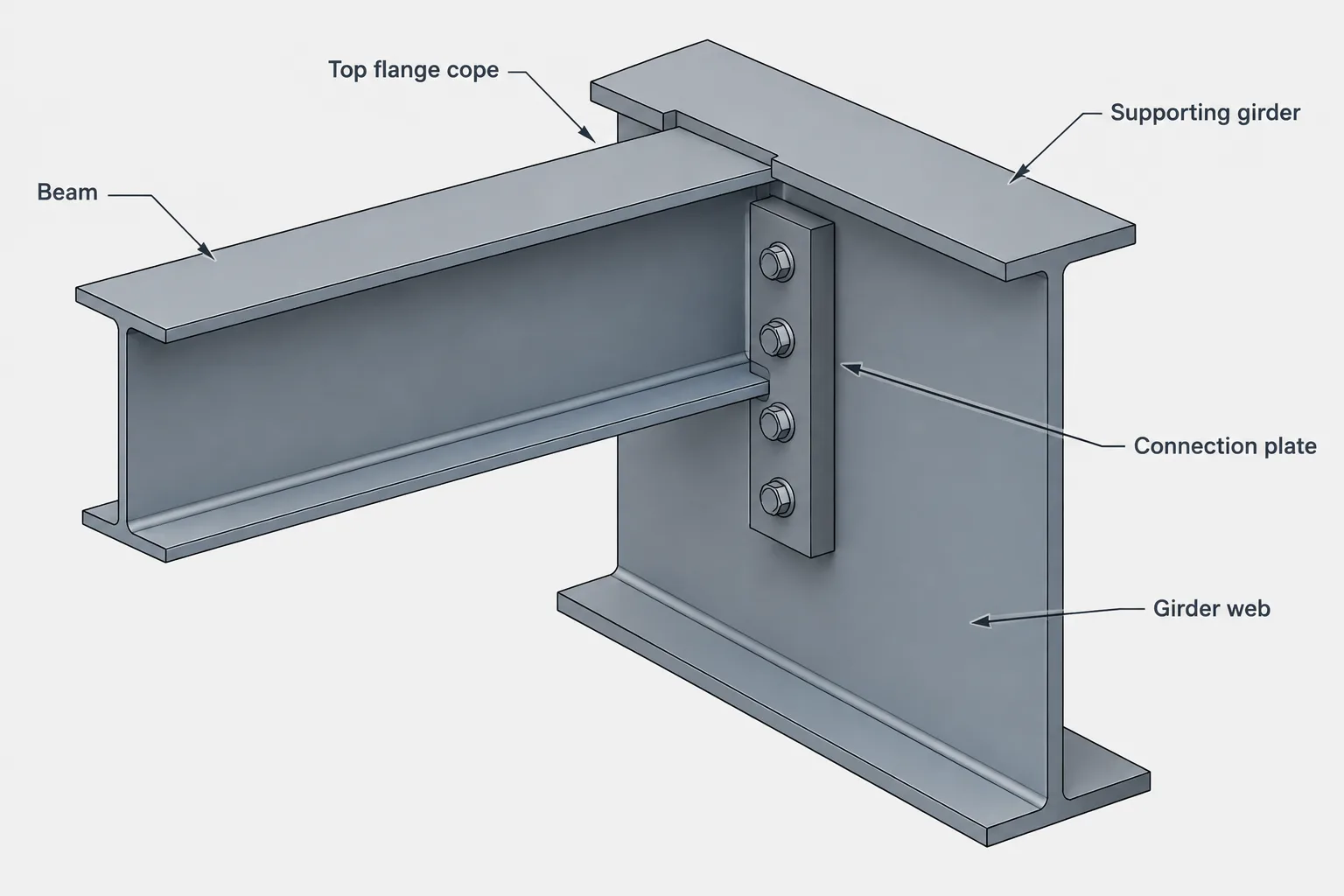
- Coordinate connections: Check flange, web, and root-clearance conditions when laying out plates, bolts, welds, stiffeners, or copes.
- Use project documents as authority: A reference profile does not replace the engineer’s design criteria, contract drawings, fabrication requirements, or supplier data.
Related reference concepts
This section can be reviewed alongside universal beam terminology, I-shape dimension conventions, section-property explanations, linear-weight calculations, steel connection detailing, and CAD block verification. These related topics help distinguish geometric reference data from structural capacity and project-specific design decisions.
Frequently asked questions
Do the numbers in the UB designation equal the exact section dimensions?
Not necessarily. A section designation identifies a standardized profile, but its designation components should not replace the actual dimensions listed in the verified reference data.
What is the difference between web thickness and flange thickness?
Web thickness describes the central vertical portion of the I-shaped profile. Flange thickness describes the top and bottom horizontal portions. Both affect connection layout, clearances, and section behavior.
Why is the root fillet radius important in CAD?
The web-to-flange junction is curved rather than a perfectly sharp internal corner. Representing or allowing for that transition helps prevent clashes with plates, weld details, bolts, and fitted components.
Can sectional area be used as a bending capacity?
No. Sectional area is a geometric property and does not by itself define bending capacity. Structural checks require other section properties, material information, member conditions, loading, and the applicable design method.
Is the DWG sufficient for fabrication or construction?
The DWG is a reference resource. Its units, scale, geometry, layers, and section identity should be checked before use. Fabrication and construction must follow approved project documents and professionally verified details.
Should the metric values be converted for a US customary-unit project?
Convert values only through a controlled project workflow, retain adequate precision, and clearly label the resulting units. Avoid mixing metric and US customary values within the same schedule or detail without explicit notation.