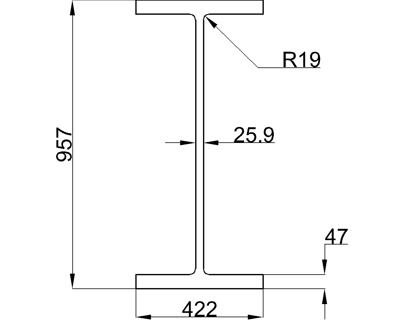
This reference page covers the UB 920x420x491 universal beam and its accompanying CAD resource. The source content records the section dimensions, root fillet radius, sectional area, and unit weight with reference to EN 10365:2017.
Use the listed data when identifying the section, coordinating a drawing, or checking a model schedule. The designation alone should not replace the detailed dimensions and properties shown in the verified source content below.
UB 920x420x491
Universal Beams
refer to : EN 10365:2017
a European standard that defines the dimensions, tolerances, and sectional properties for hot-rolled steel channels, I-beams, and H-beams used in construction and engineering. It ensures uniformity and compatibility across European structural steel products.
Dimension : 957x422x25.9×47
Depth : 957 mm
Width : 422 mm
Web Thickness : 25.9 mm
Flange Thickness : 47 mm
Root Fillet Radius : 19 mm
Sectional Area : 623.3 cm2
Unit Weight : 489.3 kg/m
How to Read the Section Data
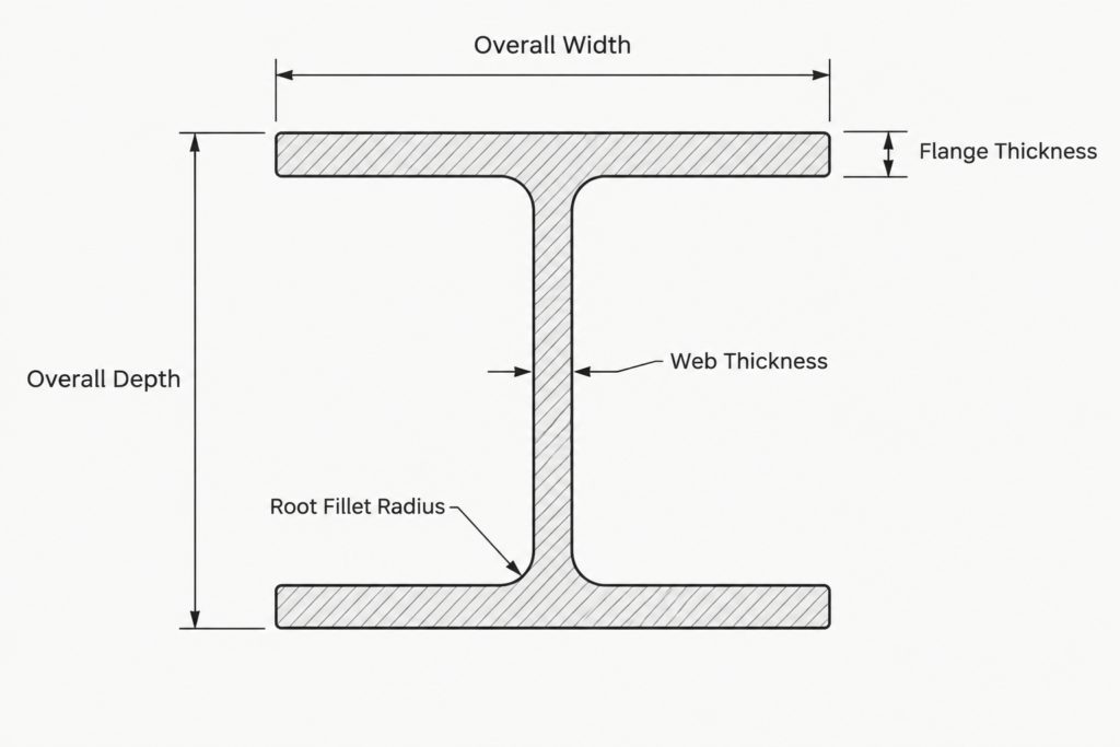
Depth and width describe the overall envelope of the universal beam. Web thickness applies to the central vertical element, while flange thickness applies to the horizontal portions of the section. These values help a drafter establish the correct profile and orientation in plans, elevations, sections, and fabrication details.
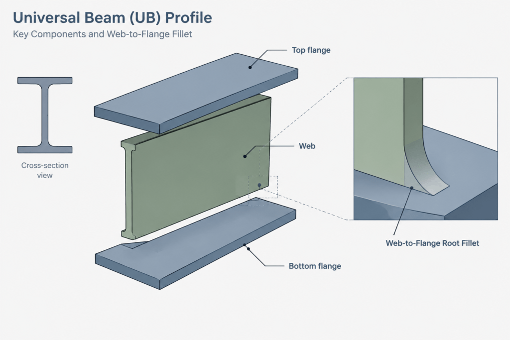
The root fillet radius describes the curved transition where the web meets a flange. This region is important when depicting the rolled profile and when checking whether nearby plates, stiffeners, bolts, weld access, or other modeled objects could interfere with the section geometry.
Sectional Area and Unit Weight
Sectional area is a geometric property of the steel cross-section. Unit weight expresses mass per unit length. They serve different purposes and should remain clearly labeled when transferring information into schedules, material lists, or calculation records.
The final element of the section designation is part of the published section name. For quantity-related work, use the unit-weight value stated in the source content rather than treating the designation as a substitute for the listed property.
Using the CAD Drawing
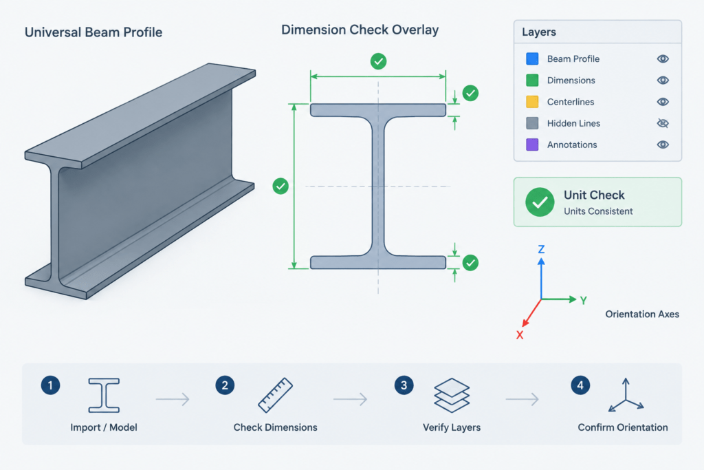
The DWG resource can support section identification, drawing setup, and coordination, but it should be checked after import. Confirm drawing units, scale, profile orientation, layer behavior, and the principal dimensions against the verified data on this page.
A section-profile drawing does not establish member capacity, connection adequacy, material grade, fabrication tolerances, or suitability for a particular structure. Those items require the applicable project documents, design criteria, and professional verification.
Related Reference Topics
Useful companion topics include universal beam designation conventions, rolled I-section geometry, flange and web terminology, root fillets, sectional-area concepts, unit-weight calculations, steel schedules, and CAD layer management. These relationships help connect section data with practical drafting and checking workflows.
Frequently Asked Questions
What type of section is UB 920x420x491?
The source identifies it as a universal beam. Its cross-section consists of two flanges connected by a central web.
Which dimensions should be checked in the CAD file?
Check the overall depth and width, web thickness, flange thickness, and root fillet geometry against the verified values in the source content. Also confirm that the file has been imported using the intended units and scale.
Why does the root fillet radius matter?
The root fillet forms the curved transition between the web and flange. Ignoring it can create an inaccurate profile or apparent clashes with plates and other connection components placed close to that junction.
Is sectional area the same as unit weight?
No. Sectional area describes the cross-sectional geometry, while unit weight describes mass along the member length. Keep the correct units attached to each value when using them in schedules or calculations.
Can the DWG be used directly for fabrication or structural design?
It should be treated as a reference resource and verified within the project workflow. Fabrication and design decisions also depend on project-specific information that is not established by a section-profile drawing alone.


