Structural steel tables contain several properties associated with torsion, but two of the most frequently misunderstood are the torsional constant J and the warping constant Cw. They describe different parts of a member’s response to twisting and should not be treated as interchangeable values.
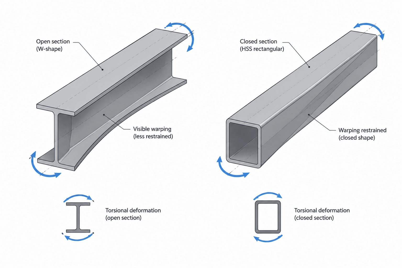
The distinction matters most for open sections such as W-shapes, channels, angles, and structural tees. These sections can twist and warp in ways that are not captured by ordinary major-axis and minor-axis bending properties. Closed sections, including many HSS profiles, generally behave differently because their connected walls provide a more effective path for torsional shear flow.
This guide explains how to interpret J and Cw, how they differ from familiar section properties, and what designers and drafters should check when torsion appears in a structural model or connection detail.
Why torsion requires its own section properties
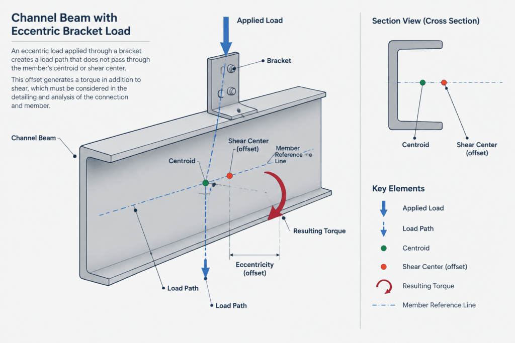
A member is subjected to torsion when the applied loading creates a twisting moment about its longitudinal axis. This can occur when a load does not pass through the section’s shear center, when a beam supports an eccentric connection, or when framing geometry transfers torque into a member.
Torsional behavior is not described adequately by the area moment of inertia alone. Values such as Ix and Iy describe resistance to bending about designated section axes. Torsion introduces shear deformation around the cross-section and, for many shapes, longitudinal warping of the member.
Two broad components are commonly considered:
- Uniform, or Saint-Venant, torsion: twisting associated with torsional shear deformation of the cross-section.
- Warping torsion: additional behavior that develops when an open section’s natural warping is restrained or varies along the member.
The torsional constant J is associated with uniform torsion. The warping constant Cw characterizes the section’s resistance to warping-related deformation.
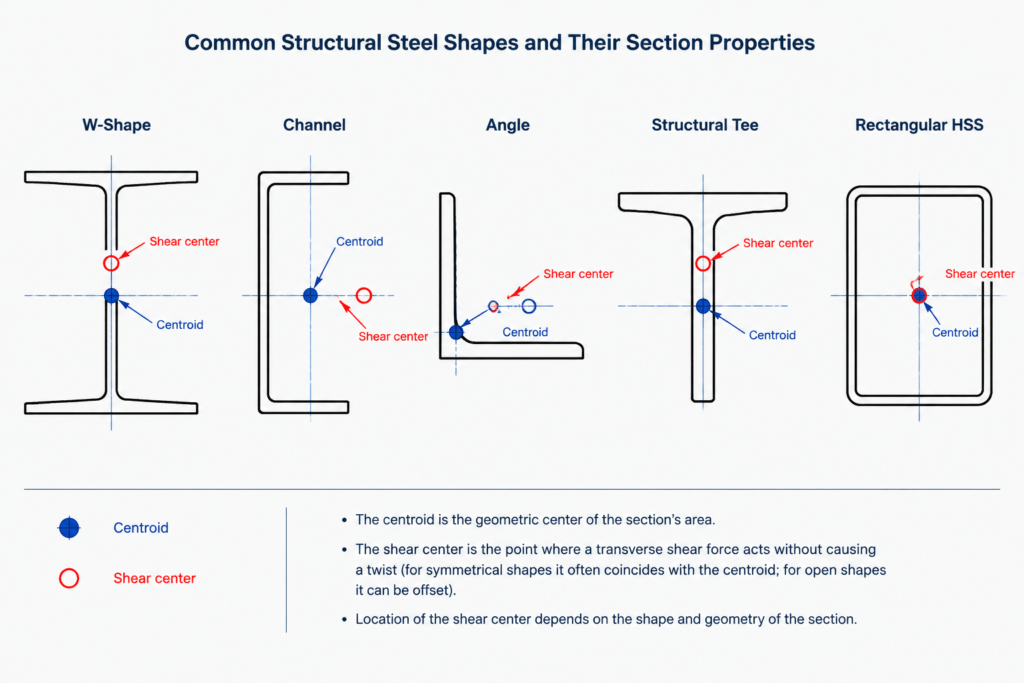
What the torsional constant J represents
The torsional constant J is a geometric section property used in the relationship between torque, twist, material shear stiffness, and member length for uniform torsion. Its units are length to the fourth power, which may look familiar because area moments of inertia use the same dimensional units.
Matching units do not make J equivalent to Ix, Iy, or the polar area moment. For most noncircular structural shapes, the torsional constant is not obtained simply by adding the two bending moments of inertia.
J is not generally the polar moment of inertia
The polar area moment about a point is the sum of two perpendicular area moments through that point. It is useful in particular mechanics relationships, especially for circular sections. For a W-shape, channel, angle, rectangular HSS, or other noncircular section, substituting the polar area moment for the tabulated torsional constant can produce an incorrect representation of torsional stiffness.
When a verified shape table supplies J, that value should be used with the corresponding shape and unit system. If a custom built-up section must be evaluated, the calculation method needs to match its actual geometry, wall connectivity, and thickness assumptions.
Open and closed sections behave differently
Open thin-walled sections typically have relatively low uniform torsional stiffness compared with closed sections of broadly comparable overall size and material quantity. In an open section, torsional shear does not circulate through a fully enclosed wall path. A closed section permits shear flow around its perimeter, which usually makes it more efficient in resisting twist.
This is why replacing a W-shape with an HSS cannot be evaluated only by comparing depth, weight, or bending inertia. Torsional behavior may change substantially even when some bending properties appear similar.
What the warping constant Cw represents
When an open section twists, points in its cross-section may move longitudinally by different amounts. This out-of-plane movement of the cross-section is called warping. If the member can warp freely and the twist is uniform, warping-related restraint effects may be limited. If an end connection, intermediate brace, diaphragm, or changing torque prevents that movement, additional stresses and internal actions can develop.
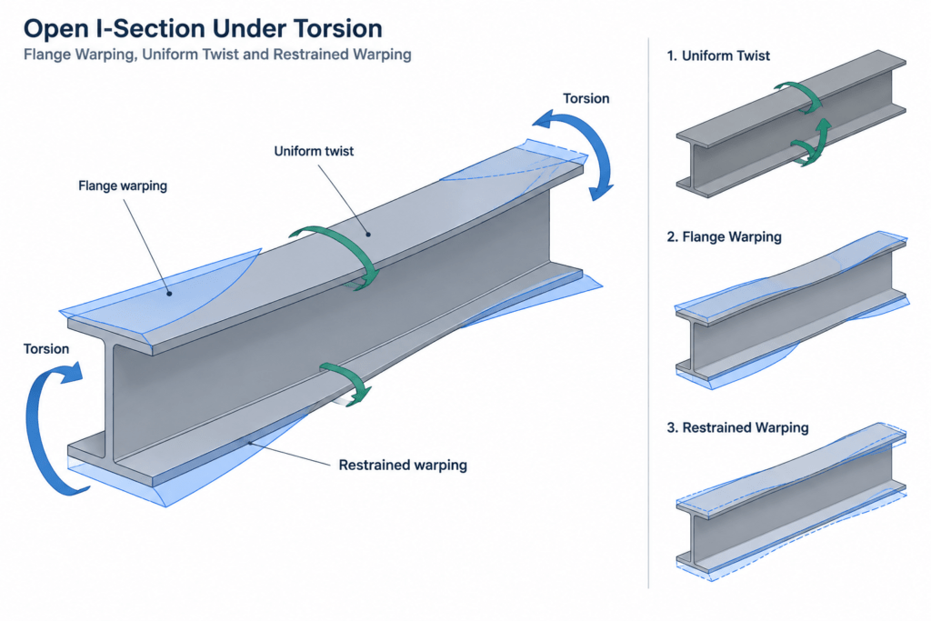
The warping constant Cw is a geometric property used to characterize resistance to this warping behavior. Its units are length to the sixth power. It is especially relevant to open sections and to analyses involving restrained torsion, lateral-torsional behavior, or stability formulations that include warping stiffness.
A large Cw does not mean that a member is automatically adequate for a torsional loading condition. Member length, end restraint, load position, material stiffness, bracing, connection behavior, and the distribution of torque all affect the response.
J and Cw compared
| Property | Primary meaning | Dimensional units | Typical relevance |
|---|---|---|---|
| J | Resistance associated with uniform torsional shear deformation | Length to the fourth power | Twist under Saint-Venant torsion for open or closed sections |
| Cw | Geometric resistance associated with cross-section warping | Length to the sixth power | Restrained torsion, nonuniform torsion, and certain stability calculations |
| Ix, Iy | Area moments used for bending about defined axes | Length to the fourth power | Flexural stiffness, deflection, stress, and stability about the corresponding axis |
| Polar area moment | Sum of perpendicular area moments about a point | Length to the fourth power | Not a general substitute for J in noncircular steel shapes |
How section type affects torsional interpretation
W-shapes and other doubly symmetric I-sections
A W-shape has its centroid and shear center at the intersection of its symmetry axes. Loading through that location avoids torsion caused solely by cross-sectional eccentricity. However, loads applied through brackets, shelf angles, edge connections, or offset framing may still create torque.
W-shapes are open sections. Their flanges can develop significant longitudinal warping when the member twists, making both J and Cw relevant in a sufficiently detailed torsional analysis.
Channels, angles, and structural tees
For channels and many other singly symmetric or unsymmetric open sections, the shear center does not generally coincide with the centroid. A force that appears centered on the visible profile may therefore cause both bending and twisting.
Angles and tees also require careful attention to axis definitions, principal directions, connection eccentricity, and restraint. A line in a CAD model placed at the centroid does not automatically represent the shear-center line or the actual load path.
HSS and other closed sections
Closed HSS profiles usually provide substantially different torsional behavior because their walls form a continuous closed path. Uniform torsional response is often more prominent than the open-section warping behavior associated with W-shapes and channels.
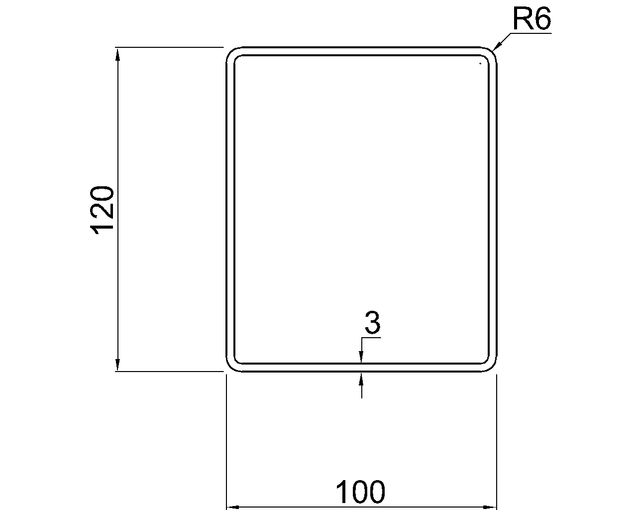
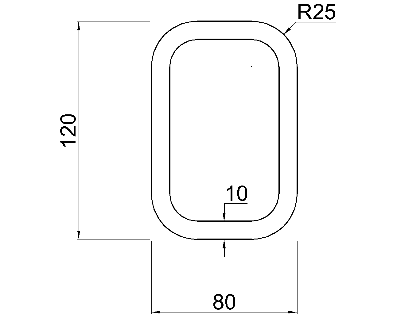
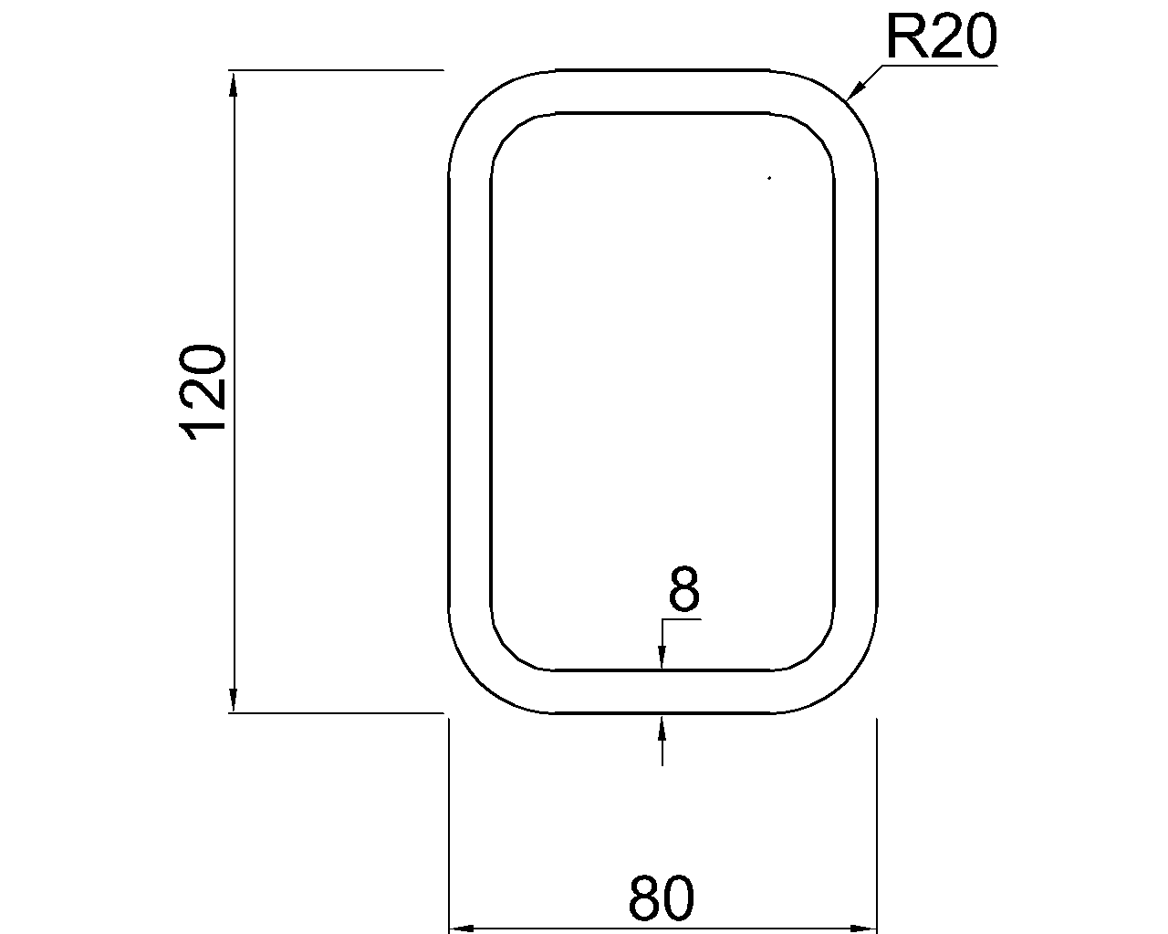
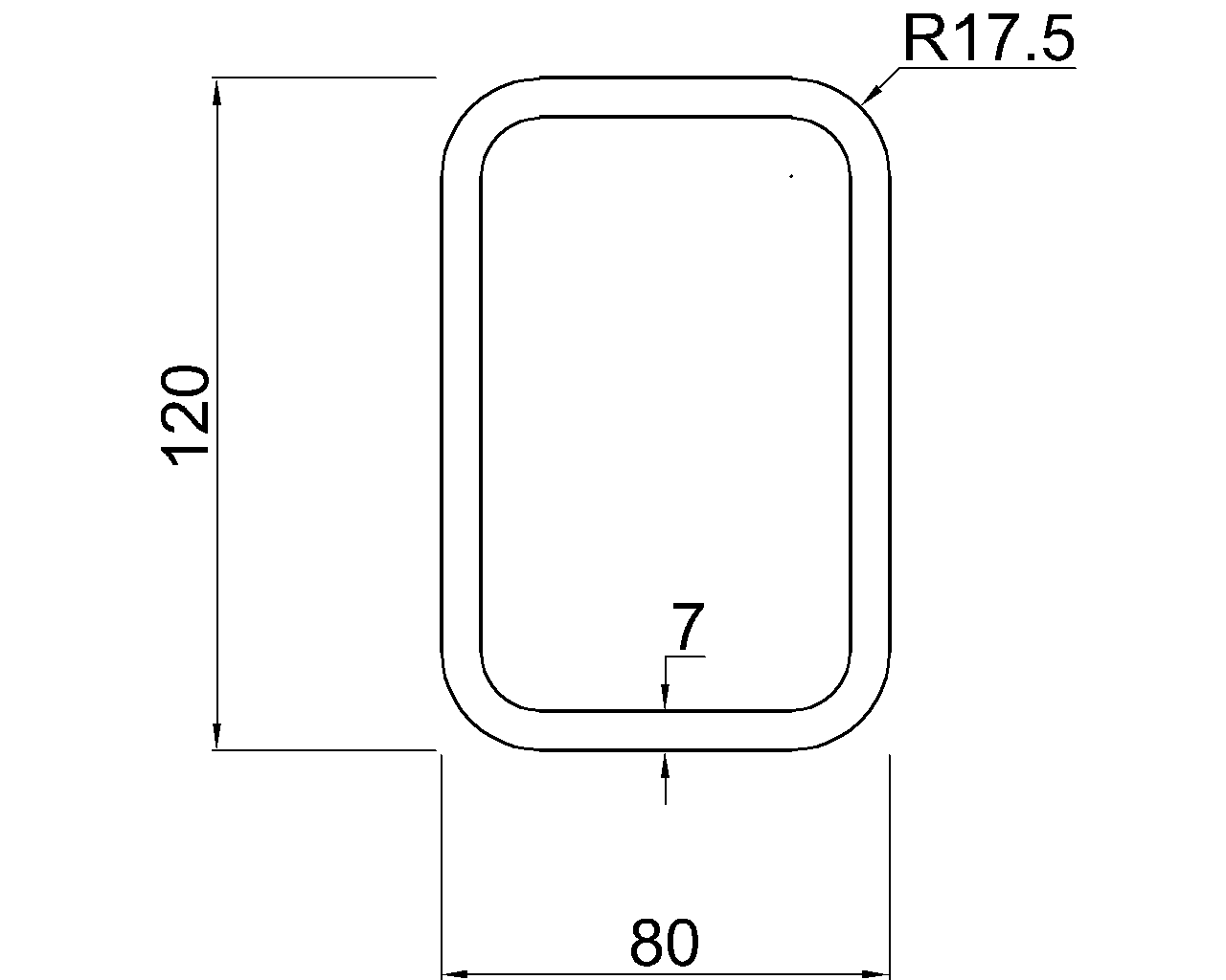
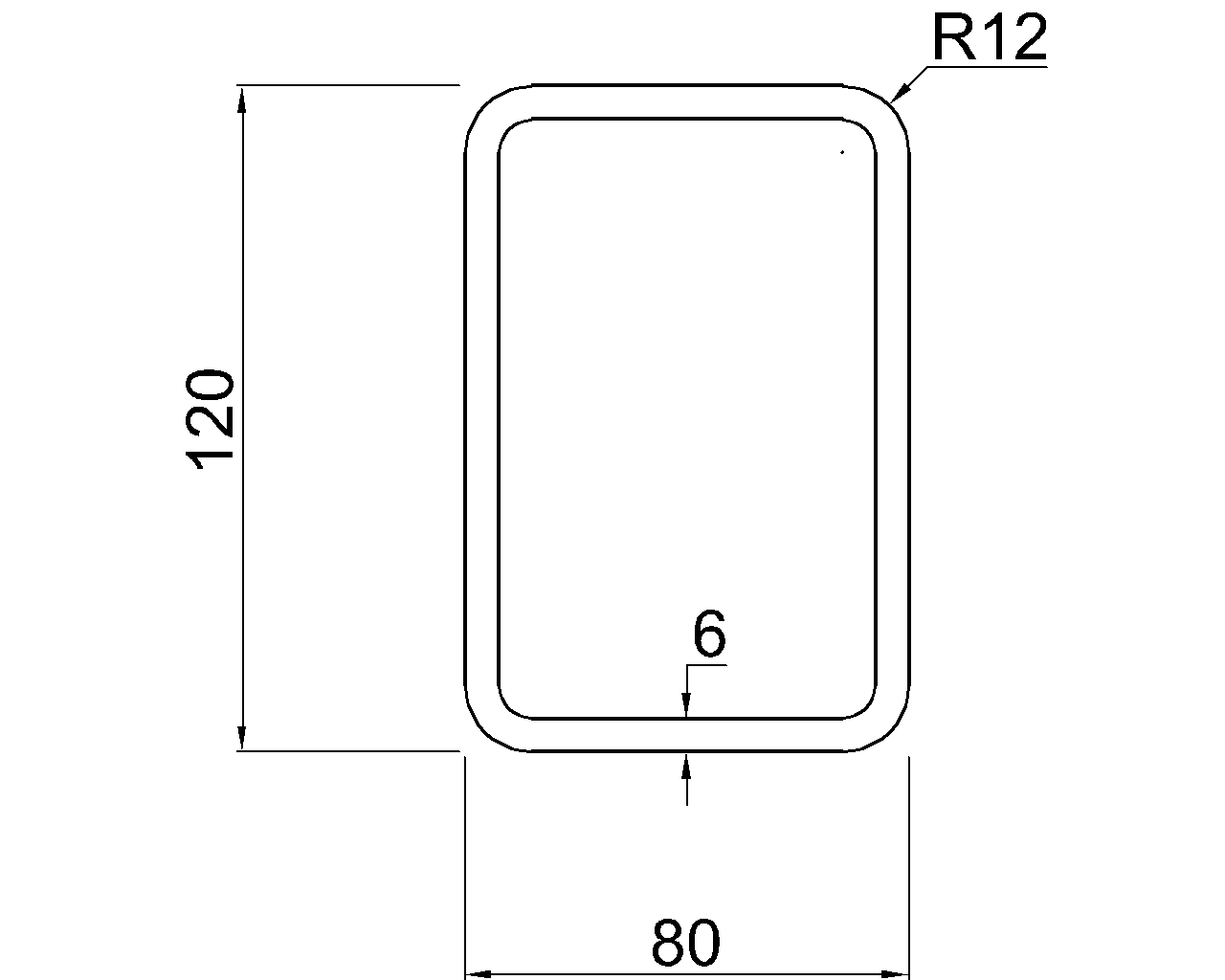
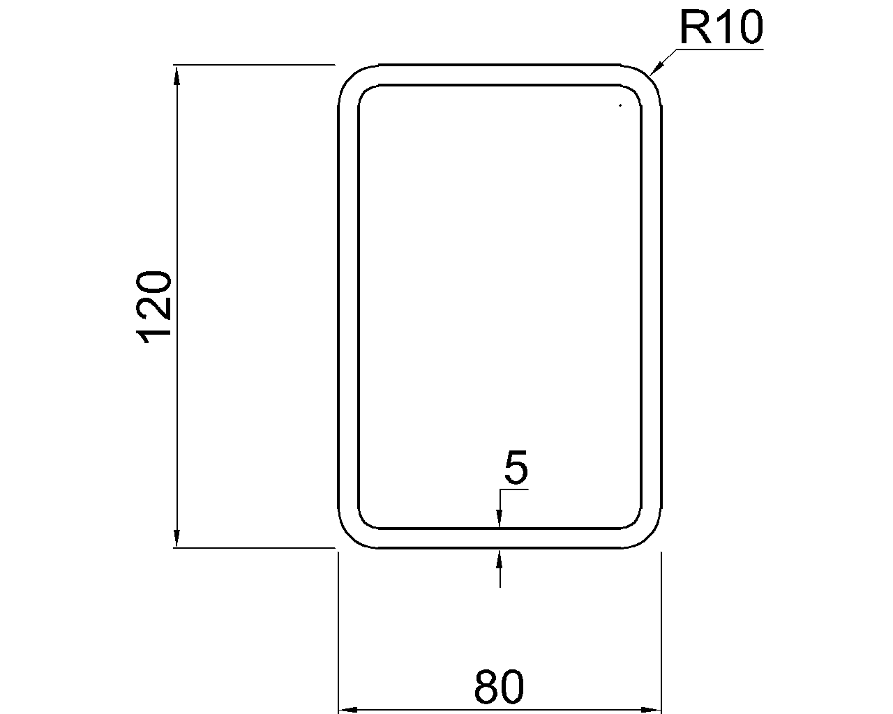
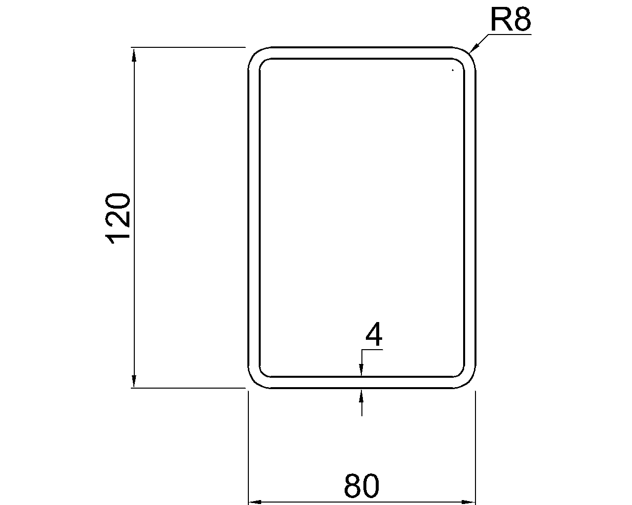
Designers should still use verified properties for the exact HSS designation. Corner geometry, wall thickness conventions, and section type affect calculated properties, so an idealized sharp-corner rectangle should not automatically replace published data.
The shear center and load placement
The shear center is the point in the cross-section through which a transverse load can act without producing twist from that load alone. For a doubly symmetric W-shape, it coincides with the centroid. For a channel, angle, tee, or other nonsymmetric section, its location may be offset and can even lie outside the material boundary.
This concept is important in both analysis and detailing. An eccentric connection can introduce torsion even if the supporting member was initially selected for bending. Examples include beams supporting loads on one flange, channels connected through one side, and members carrying equipment or façade attachments on brackets.
Practical CAD and modeling workflow
A useful torsion review begins before section properties are entered into analysis software. The model geometry and drawing details must represent how the load actually reaches the member.
- Confirm the section designation. Do not transfer J or Cw from a visually similar shape.
- Check the unit system. Torsional and warping properties use high powers of length, so an unnoticed imperial-to-metric conversion error can be severe.
- Verify local-axis orientation. A rotated channel or angle may have the correct shape properties but an incorrect modeled load direction.
- Show the real connection offset. Centerline-only framing can hide eccentricity between the supported load and the member’s shear center.
- Represent restraints realistically. A connection that restrains rotation does not necessarily provide full warping restraint, and a simple support symbol does not define every torsional boundary condition.
- Review openings and attachments. Copes, notches, stiffeners, end plates, diaphragms, and concentrated connections can alter local behavior even when the gross-section table values remain unchanged.
- Keep source data traceable. Record the shape database, unit convention, and property definitions used in the model rather than relying on manually copied values without context.
Common mistakes to avoid
- Using Ix + Iy as the torsional constant for a noncircular steel section.
- Comparing J values without confirming that both shapes use the same units.
- Assuming a load through the centroid also passes through the shear center for every shape.
- Ignoring warping because the analysis model includes a rotational restraint.
- Assuming two members with similar bending inertia will have similar torsional stiffness.
- Using gross-section table properties to represent a heavily modified, built-up, or locally cut section without evaluation.
Using shape-table properties responsibly
Values of J and Cw are starting points for analysis, not standalone capacities. They describe cross-sectional geometry but do not define loading, member length, material stiffness, boundary conditions, connection flexibility, or applicable limit states.
For routine reference work, first identify whether the section is open or closed, locate the shear center relative to the load path, and determine whether warping can occur freely or is restrained. These checks help clarify which torsional effects may matter and whether a simple model is sufficient. Final member and connection decisions should be based on verified project data, the governing design criteria, and an analysis method appropriate to the actual structural system.