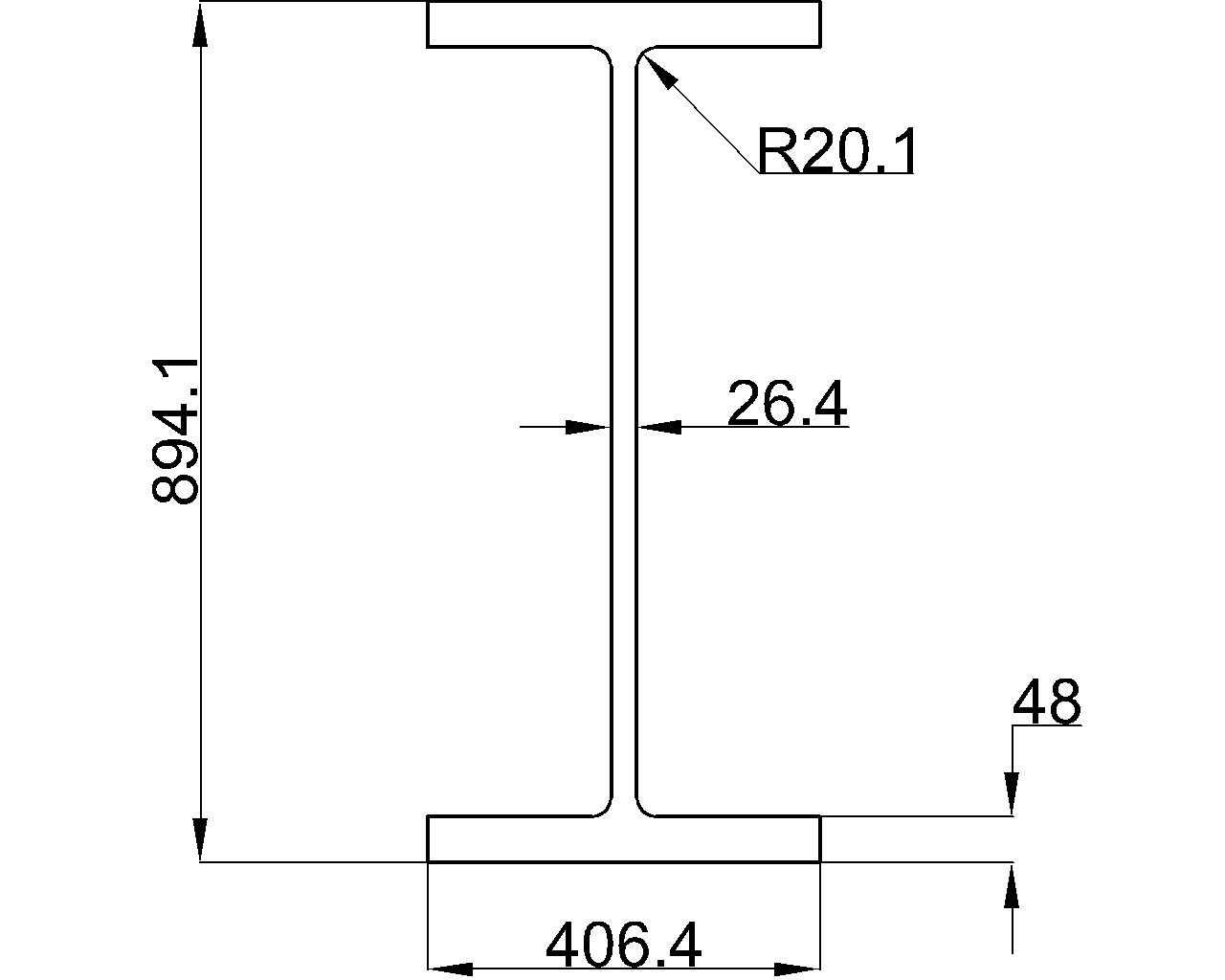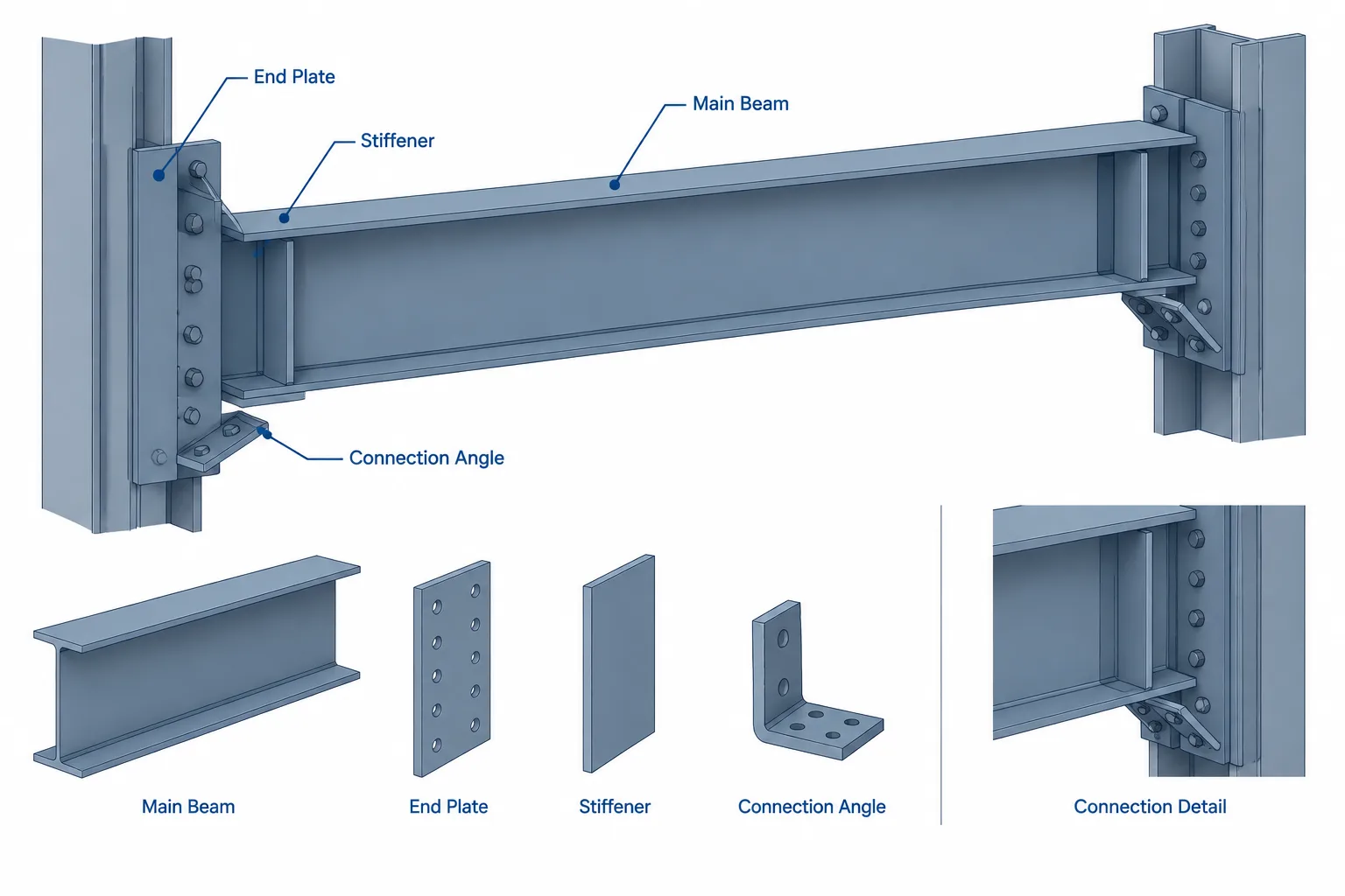
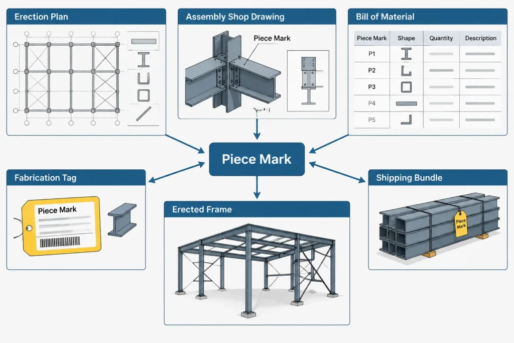
Structural steel piece marks connect the information shown on drawings with the physical material moving through a fabrication shop and onto a jobsite. A mark may identify a single loose part, a fabricated member, or another tracked item, depending on the fabricator’s system and the project requirements.
Although marks often look like simple combinations of letters and numbers, they support several important tasks: finding the correct shop drawing, grouping identical items, preparing bills of material, tracking fabrication status, organizing shipments, and placing members during erection. Understanding what a mark represents is therefore essential when reviewing structural steel drawings or building a reliable CAD model.
What Is a Structural Steel Piece Mark?
A piece mark is a unique identifier assigned to a steel item or group of equivalent items. It functions as a reference key rather than a dimensional description. The mark itself generally does not tell the reader everything about the member’s shape, length, material, finish, or connection geometry. Those details must come from the associated drawing, model, bill of material, or project database.
Terminology varies among fabricators. In one workflow, “piece mark” may refer specifically to an individual plate or angle. In another, the same term may be used for a complete fabricated beam. Before interpreting a mark, determine how the project distinguishes parts, assemblies, main members, and shipping items.
Part Marks, Assembly Marks, and Erection Marks
Several types of identifiers may appear during detailing and fabrication. Their exact names are not universal, but the following distinctions are common.
| Identifier type | Typical use | What it may represent |
|---|---|---|
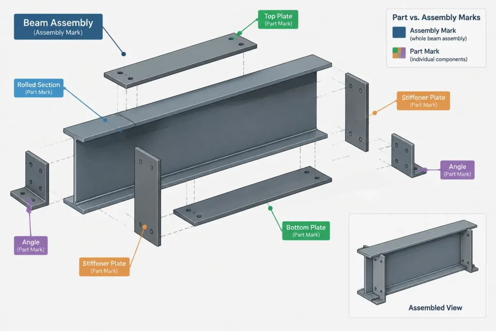
| Part mark | Shop cutting, sorting, and fitting | A plate, angle, tee, bar, stiffener, clip, or other individual component |
| Assembly mark | Shop drawing and fabrication control | A main member together with the parts attached to it |
| Erection mark | Field identification and placement | A fabricated beam, column, brace, frame, or other item delivered for erection |
| Shipping or bundle mark | Loading and delivery organization | A shipment group, bundle, sequence, or zone rather than one structural member |
A beam assembly, for example, may have one primary mark while its shear plates, stiffeners, and connection angles carry separate submarks. The assembly drawing gathers those components under the primary mark and shows how they are fitted and welded or bolted together.
Why the Shape Designation Is Not the Piece Mark
A rolled-shape designation identifies a section size, but it does not uniquely identify a fabricated member. Multiple beams can use the same W-shape while having different lengths, end cuts, hole patterns, camber instructions, coatings, or attached plates. Each distinct fabrication condition may require its own mark.
Conversely, several members may share one mark when their fabrication information is truly equivalent under the project’s marking rules. A quantity is then associated with that mark. This approach reduces duplicate shop drawings and allows identical members to be fabricated from a common set of instructions.
The decision to combine items should not be based on section size and length alone. Material specification, connection geometry, hole orientation, handedness, finish, preparation, and other controlled attributes must also agree.
What Makes Two Steel Items Identical?
For marking purposes, geometric similarity is only the starting point. Detailers should compare all information that affects purchasing, fabrication, inspection, delivery, or erection. Typical checks include:
- Shape or plate description
- Material designation required by the project documents
- Overall length and end geometry
- Hole sizes, types, locations, and orientation
- Copes, notches, bevels, miters, and other cuts
- Attached plates, angles, stiffeners, or connection material
- Weld locations and shop-versus-field designation
- Surface preparation, coating, or areas intentionally left uncoated
- Camber, sweep orientation, or other geometric instructions
- Handed or mirrored configuration
If one of these attributes differs, assigning a separate mark is often the clearer choice. The controlling decision should follow the fabricator’s procedures and the project’s approved detailing conventions.
Mirrored Parts Require Special Attention
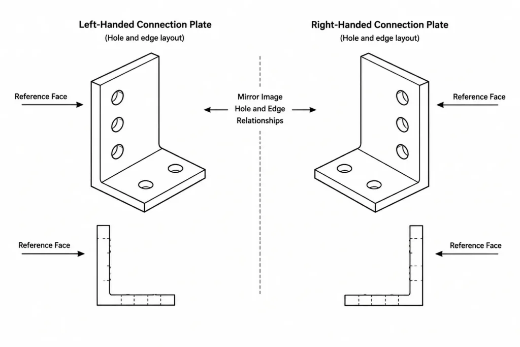
Two components can have the same outline and dimensions yet still be opposite-hand parts. A connection plate drilled near one edge may become a different item when mirrored. The same issue occurs with offset holes, skewed end plates, unequal clip angles, and members with attachments on only one side.
CAD software can make mirrored parts look deceptively interchangeable, especially when views are rotated. A reliable check should use a consistent reference face and member orientation. Labels such as near side, far side, left end, right end, top, and bottom must be interpreted from the drawing’s stated viewing direction rather than from screen position alone.
How Marks Relate to Shop Drawings and Bills of Material
The assembly mark is commonly the main lookup key for a shop drawing. The drawing shows the member views, dimensions, connection details, and a material list for the components needed to fabricate that assembly. Individual part marks in the material list should correspond to callouts in the drawing views.
A useful cross-check follows this path:
- Locate the assembly mark in the erection plan or member schedule.
- Open the matching shop drawing or model object.
- Confirm the main-member shape, length, and orientation.
- Match every called-out subpart to the bill of material.
- Verify that listed quantities account for repeated parts.
- Check that loose items are clearly distinguished from shop-attached items.
This traceability helps reveal missing callouts, duplicate marks, quantity errors, and parts that exist in the material list but are not shown in a view.
Piece Marks in CAD and Model-Based Workflows
In a model-based workflow, a mark should be treated as managed data rather than ordinary annotation. Text placed manually beside a member can become disconnected from the object when the model changes. Where the software and office workflow permit, the displayed label should derive from the member or assembly record used to generate drawings and reports.
Useful object data may include the current mark, preliminary identifier, section designation, material, phase, sequence, drawing status, and revision state. The exact fields depend on the detailing platform and fabricator’s production system.
Marks should also remain readable in exported two-dimensional files. A recipient opening a neutral CAD drawing may not have access to the original model database. Clear text, sensible layer organization, and an explicit drawing title help preserve the relationship between the visible geometry and its identifier.
Avoid Using Marks as Geometry
Do not infer a member’s size or location from its identifier unless a documented project convention explicitly supports that interpretation. Prefixes may help classify beams, columns, braces, plates, or miscellaneous items, but they are not a substitute for dimensions and shape callouts. A mark that begins with a particular letter does not independently prove the member type.
Managing Marks During Revisions
Revisions create one of the most important marking decisions: whether an existing mark should remain or a new mark should be assigned. Changing a mark can disrupt drawing references, material tracking, fabrication records, and erection plans. Keeping a mark after significant fabrication changes can be equally risky if old and new versions become confused.
A disciplined revision review should determine:
- Whether material has already been ordered, cut, assembled, coated, or shipped
- Whether the revised item remains interchangeable with previously detailed quantities
- Which drawings, reports, tags, and model views reference the mark
- Whether an existing physical item requires rework or replacement
- How the change will be communicated to the shop and field
There is no universal rule that fits every production system. The detailer should follow the project’s revision and release procedures rather than renumbering items only to make a drawing set look orderly.
Practical Marking Checks Before Release
Before issuing fabrication or erection information, perform a coordinated mark review rather than checking each drawing in isolation.
- Confirm that every erection-plan mark has a corresponding assembly drawing or defined source.
- Check that no mark has been unintentionally assigned to different geometry.
- Confirm that identical marks have matching material, fabrication, and finish information.
- Review left-hand and right-hand conditions.
- Match assembly quantities across plans, drawings, schedules, and reports.
- Verify that loose parts are identified and associated with the correct destination.
- Check revised marks against previously released material.
- Ensure labels remain legible and unambiguous in plotted and exported drawings.
Marks Are a Coordination System, Not Just Labels
Structural steel piece marks provide a shared language for detailing, purchasing, fabrication, shipping, and erection. Their value depends on consistency: one identifier must lead users to the correct geometry, material, drawing, quantity, and physical item.
A strong marking workflow combines clear naming conventions with careful comparison of member attributes, controlled revision practices, and coordinated drawing data. When marks are treated as part of the project information system rather than simple text notes, they help reduce fabrication ambiguity and make steel drawings easier to use from the office to the field.