Structural steel beam web openings allow ducts, pipes, conduits, and other building services to pass through a framing member rather than below it. They can reduce floor-zone depth and simplify routing, but they also remove material from a critical part of the beam. An opening therefore cannot be treated as an ordinary drafting cutout or added solely because it fits within the visible web.
Successful web-opening details begin with coordinated geometry and an engineered load path. The structural drawings, connection design, fabrication model, and MEP layout must agree on the opening’s size, shape, position, reinforcement, and relationship to nearby features. Published shape dimensions are essential for establishing the available web region, but they do not determine whether an opening is structurally acceptable.
What Counts as a Beam Web Opening?
A web opening is an intentional penetration through the web of a rolled or built-up steel member. It is distinct from a beam cope, which removes material near an end to provide connection or erection clearance. It is also different from bolt holes associated with a connection, even though both remove web material.
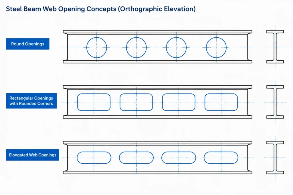
Common opening forms include:
- Round openings: Frequently coordinated with circular pipes or sleeves and free from sharp geometric corners.
- Rectangular openings: Useful for ducts and grouped services, but corner geometry and reinforcement require careful definition.
- Elongated openings: Sometimes used where service routing needs adjustment along the member.
- Multiple openings: A series of penetrations whose spacing and combined effect must be evaluated, not merely each opening in isolation.
- Fabricated cellular or castellated configurations: Members produced with a planned pattern of openings. These are engineered member systems rather than field-modified standard beams.
An opening may be unreinforced or reinforced, depending on the engineering evaluation. Its acceptability depends on more than the beam designation and opening dimensions.
Why Web Openings Affect the Load Path
The web plays a major role in transferring shear and also participates in the beam’s overall flexural behavior. Removing part of it redirects stresses around the opening. The remaining web above and below the penetration acts as separate segments connected through the surrounding material, and localized bending can develop around the opening.
Engineers may consider effects such as reduced shear capacity, local bending around the opening, interaction between shear and flexure, web buckling, stress concentration, and the behavior of welds or reinforcement. Large openings may produce frame-like action around the perimeter, often described as Vierendeel action.
The effect is sensitive to location. A penetration near a support, concentrated load, connection, or abrupt change in section can behave differently from one in a less highly stressed region. For that reason, rules such as “keep it near midspan” or “place it in the middle of the web” are not universal design approvals. The actual member, loading, restraint, connection geometry, and opening arrangement must be checked by the responsible engineer.
Geometry That Must Be Coordinated
A useful opening detail defines the penetration relative to stable references. A circle floating in a beam elevation without dimensions is not adequate fabrication information.
| Item | What the detail should communicate |
|---|---|
| Member identity | Beam mark and shape designation tied to the framing documents |
| Opening size | Diameter, width and height, or other defining geometry |
| Longitudinal location | Position from a work point, beam end, grid line, column line, or another controlled reference |
| Vertical location | Centerline or edge location relative to top of steel, bottom of steel, or beam centerline |
| Shape and corners | Round, rectangular, elongated, or specially formed geometry, including corner treatment where required |
| Nearby features | Connections, stiffeners, splices, holes, attachments, concentrated loads, and other openings |
| Reinforcement | Plate or shape arrangement, limits, orientation, and weld information supplied by the design documents |
| Service information | Intended duct, pipe, sleeve, clearance zone, or reserved opening identifier |
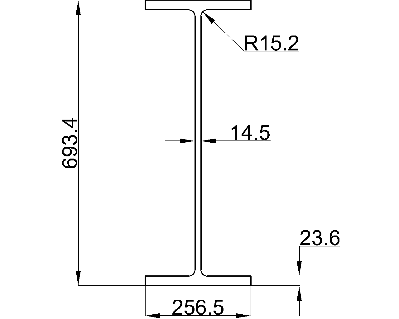
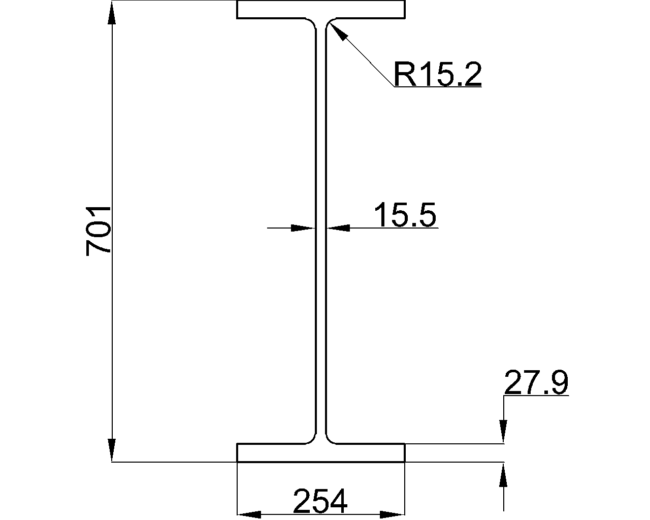
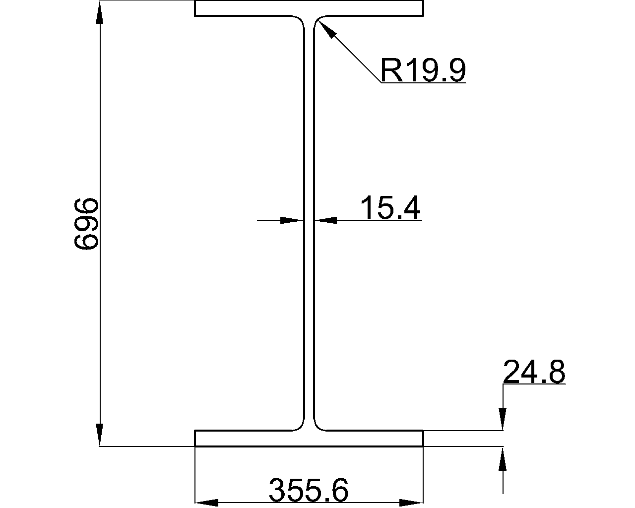
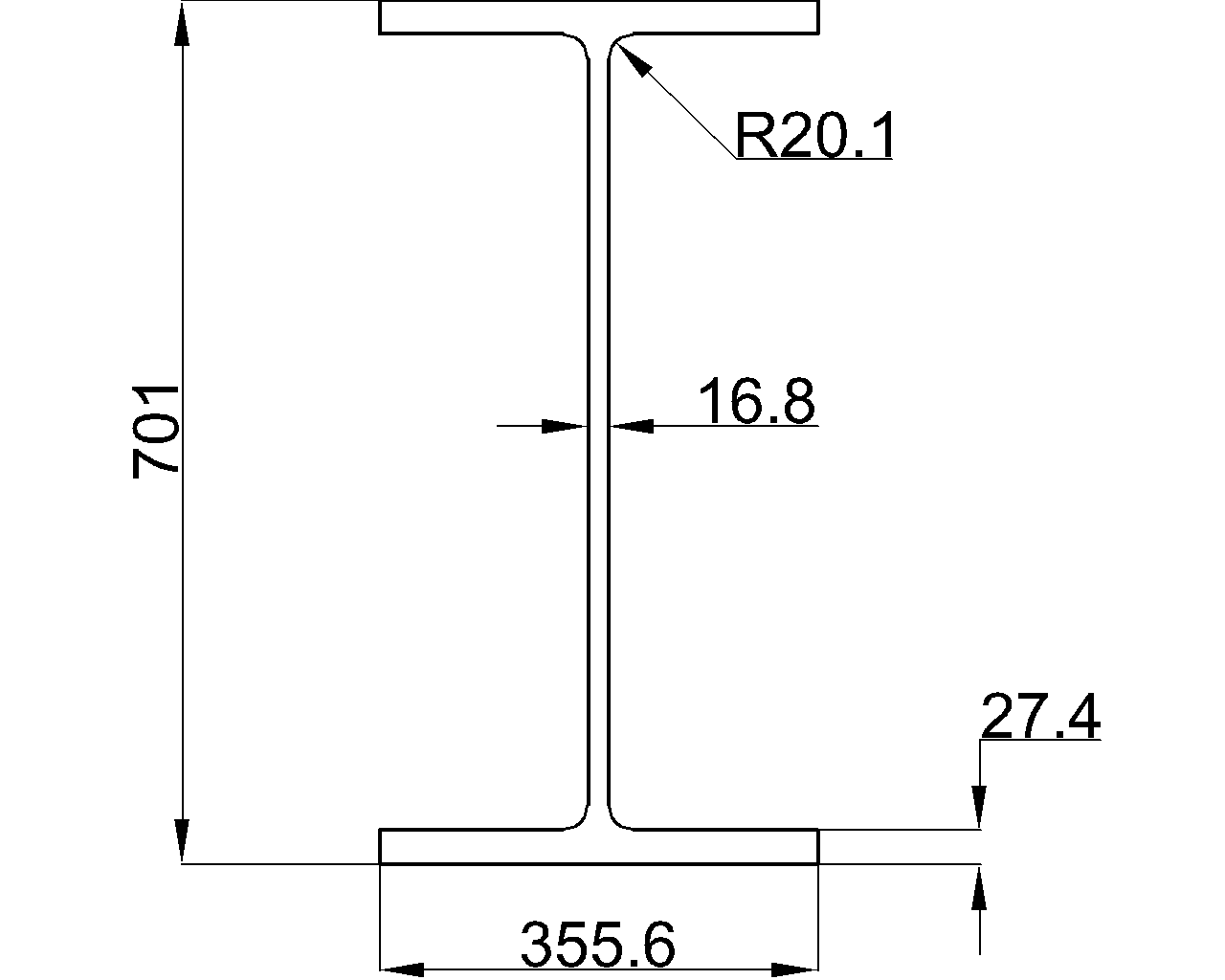
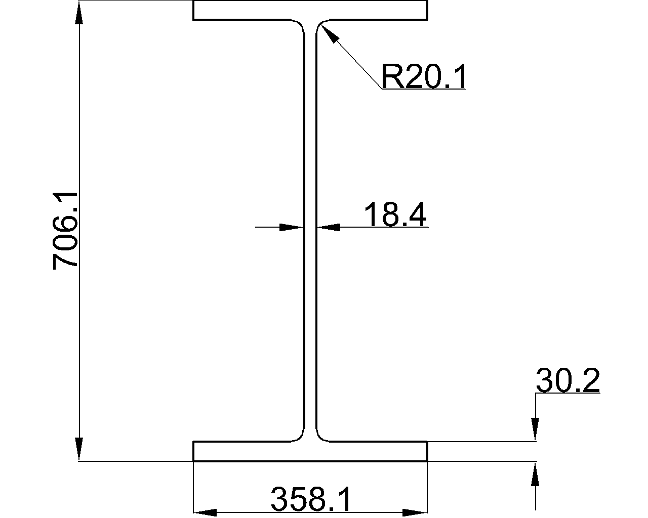
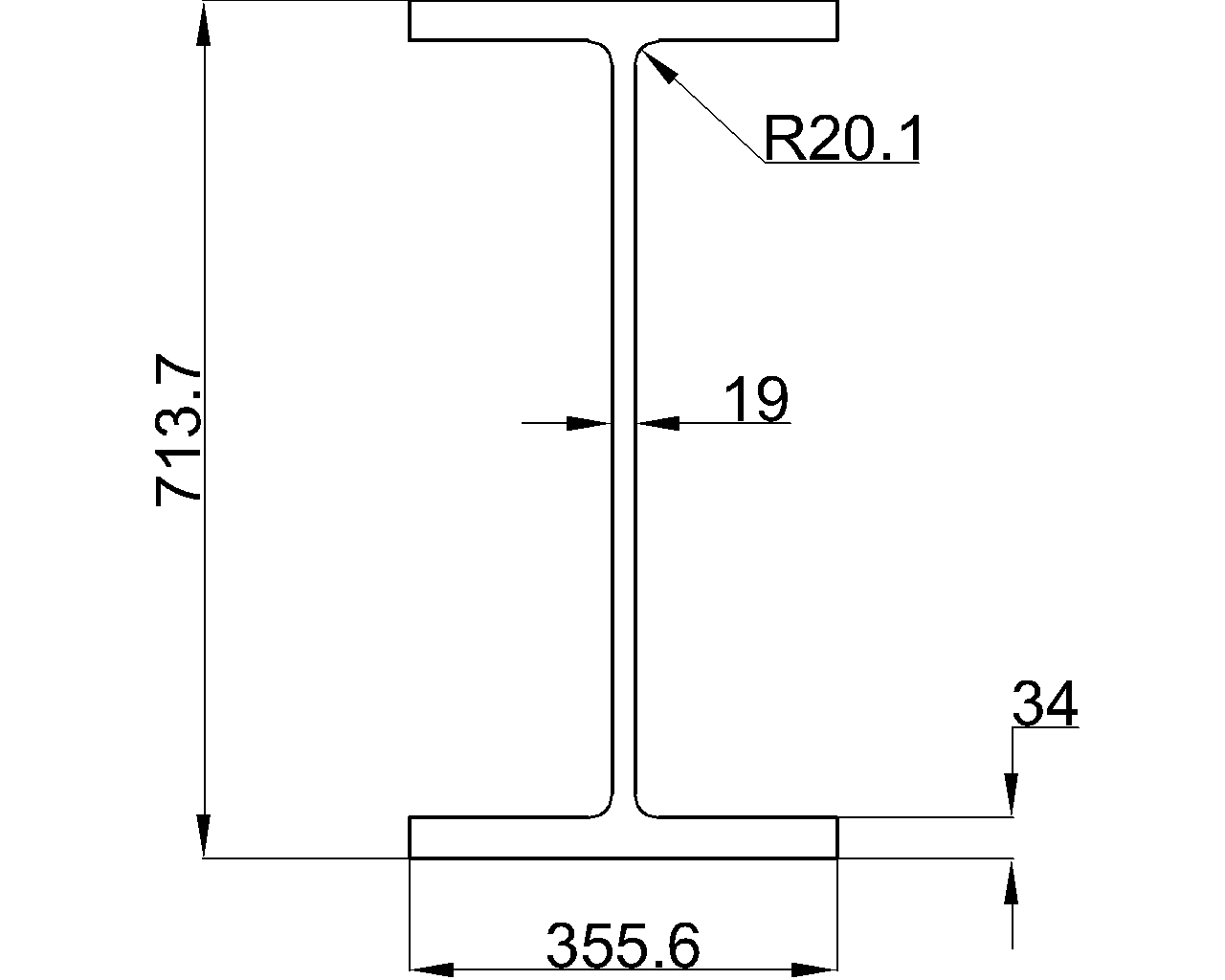
Vertical dimensions deserve special attention. The nominal depth in a shape designation is not necessarily the exact overall depth, and the clear web region is less than the distance between the outer flange surfaces. Flange thickness, rolled fillets, and detailing clearances reduce the usable area. Shape-table dimensions should therefore be used when constructing or checking the section.
Opening Reinforcement Concepts
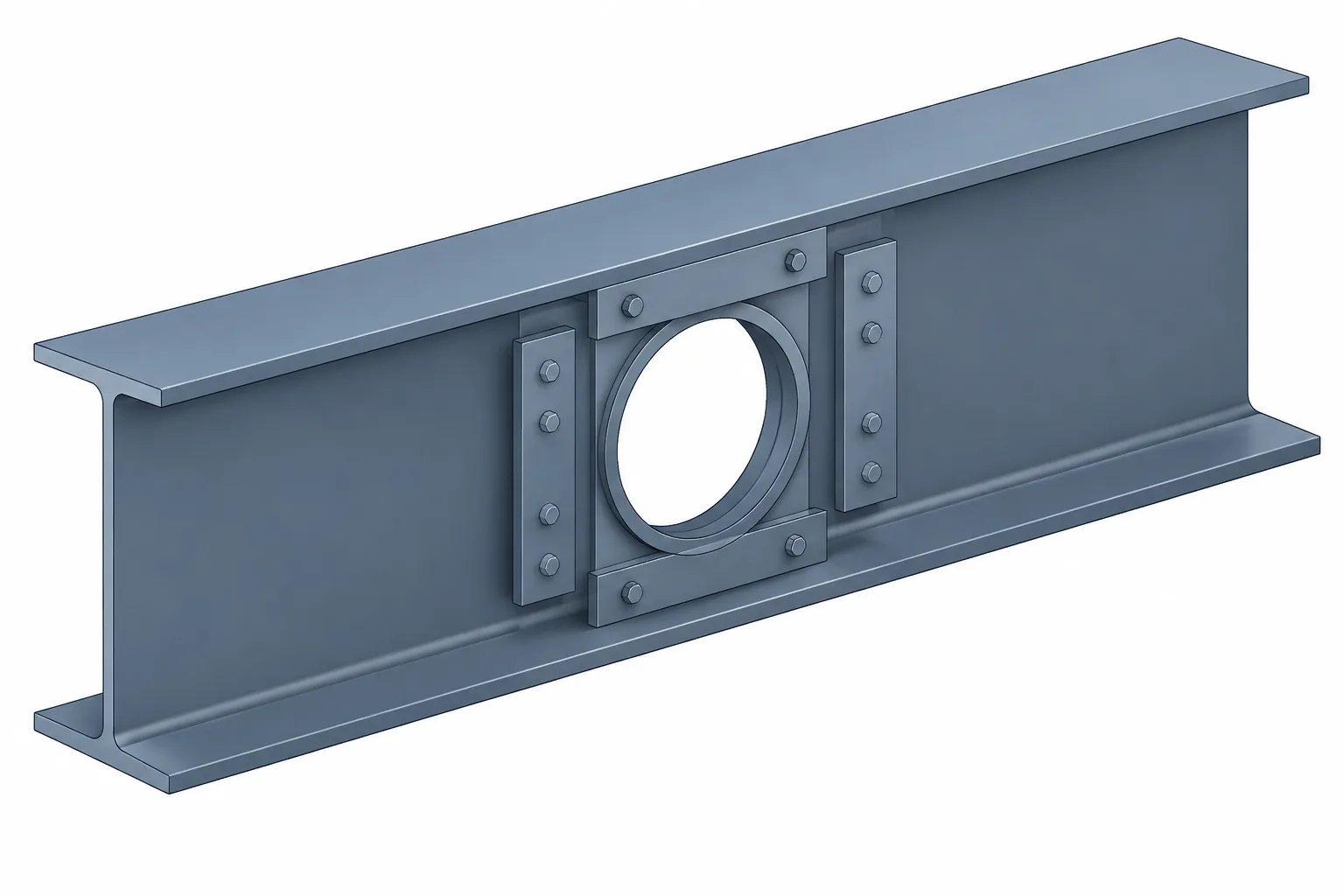
Reinforcement is intended to help redirect forces around removed web material. Its configuration must come from engineering design rather than drafting convention. Common concepts include horizontal plates above and below an opening, vertical plates at its sides, a framed perimeter, web doubler material, or other purpose-designed components.
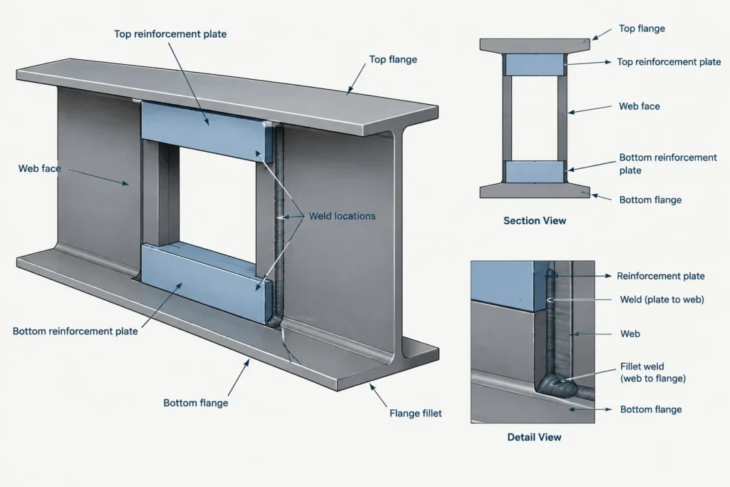
Several details that appear simple in elevation become more complex in section. A reinforcing plate may conflict with flange fillets, transverse stiffeners, shear connections, deck supports, or MEP insulation. Weld access and welding sequence may also influence the practical arrangement.
Drawings should make clear whether reinforcement is placed on one side or both sides of the web. A generic note such as “reinforce opening” does not define plate placement, extent, fit, or attachment. Likewise, copying reinforcement from another beam is unsafe unless the responsible engineer confirms that the conditions are equivalent.
Corner and Edge Definition
Rectangular openings require explicit corner geometry. A CAD rectangle with mathematically sharp corners may not represent the intended fabricated cut. Rounded corners, drilled transition holes, or another specified treatment may be required by the engineered detail and fabrication method. Drafters should depict the specified geometry rather than allowing a default polyline corner to become an accidental instruction.
The drawing should also distinguish the required finished opening from any sleeve, frame, or reinforcing plate surrounding it. MEP users often care about the unobstructed passage, while fabricators need the steel cut geometry. Those are not always the same boundary.
MEP Coordination and Clearance
A coordinated penetration must accommodate the actual service assembly, not just the nominal duct or pipe. Insulation, flanges, couplings, dampers, fire-protection components, installation tolerances, and access needs can enlarge the required clearance envelope.
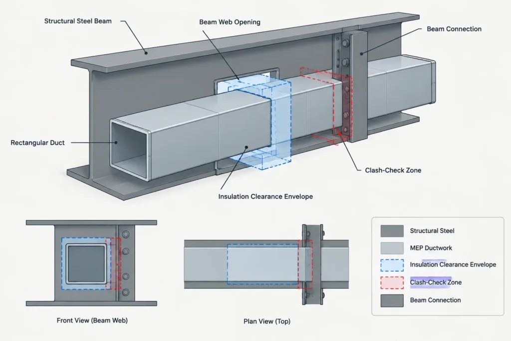
At the same time, enlarging a structural opening “for flexibility” changes the structural condition. The preferred workflow is to establish a realistic service envelope, submit it for structural review, and then freeze the approved opening geometry before fabrication. If future routing flexibility is needed, it should be planned and engineered rather than improvised in the shop or field.
Coordination models can identify obvious clashes, but clash-free does not mean structurally acceptable. A duct may pass through the modeled web without touching steel while still conflicting with reinforcement, connection bolts, weld access, or a restricted structural region.
A Practical CAD and Detailing Workflow
- Verify the member: Confirm the beam mark, orientation, actual section dimensions, end conditions, and framing references.
- Collect service requirements: Obtain the required clear passage and identify insulation, joints, access zones, and routing tolerances.
- Place a coordination object: Model the proposed opening as a separate, identifiable object rather than immediately modifying the beam solid.
- Check surrounding geometry: Review flanges, fillets, connections, stiffeners, splices, deck attachments, other penetrations, and applied-load locations.
- Obtain structural direction: Record whether the opening is accepted, revised, rejected, or requires reinforcement.
- Model the approved condition: Add the final cut and reinforcement using verified dimensions and orientations.
- Create fabrication views: Show an elevation for location, sections for plate placement, and enlarged details where geometry is congested.
- Run consistency checks: Compare plans, elevations, sections, schedules, CNC data, and coordination models before release.
Layer names, object properties, or model parameters can also identify opening status. Categories such as proposed, structurally reviewed, approved for detailing, and revised help prevent preliminary geometry from being mistaken for fabrication information.
Common Detailing Problems
- Using nominal beam depth to center the opening: This can produce incorrect vertical placement when actual section geometry differs.
- Ignoring rolled fillets: Reinforcing plates or opening edges may enter the flange-web transition region.
- Dimensioning from two independent references: Conflicting dimension chains can overconstrain the opening location.
- Showing reinforcement only in elevation: The fabricator may not know which web face receives each component.
- Failing to coordinate the connection zone: End plates, shear tabs, bolts, stiffeners, and welds may occupy the proposed area.
- Treating field cutting as a minor adjustment: An unreviewed field penetration can alter the designed member and damage coatings or nearby work.
- Reusing a typical detail without checking applicability: Similar-looking beams may have different forces, spans, openings, or connection conditions.
Final Review Checklist
Before a web-opening detail is issued, confirm that the member and opening are uniquely identified; dimensions use clear references; actual shape geometry has been considered; the clear service passage is distinguished from the steel cut; reinforcement is fully shown; nearby connections and attachments have been checked; and every view reflects the same revision.
Structural steel beam web openings are coordination-intensive features, not generic holes. Shape databases and CAD profiles provide the geometric foundation, but the final opening location and reinforcement require project-specific engineering. Careful modeling, explicit dimensions, and disciplined revision control help convert that engineering decision into reliable fabrication information.