Strong-axis and weak-axis orientation affects how a structural steel member bends, how it is braced, and how it should appear in plans, sections, models, and connection details. The concept is easy to visualize for a wide-flange shape, but it becomes less intuitive for channels, angles, structural tees, and rectangular HSS.
The terms describe geometric behavior rather than material strength. Rotating a steel section does not change the steel itself, but it changes the distribution of material relative to the bending axis. That distribution is reflected in section properties such as moment of inertia, section modulus, and radius of gyration.
What Are the Strong and Weak Axes?
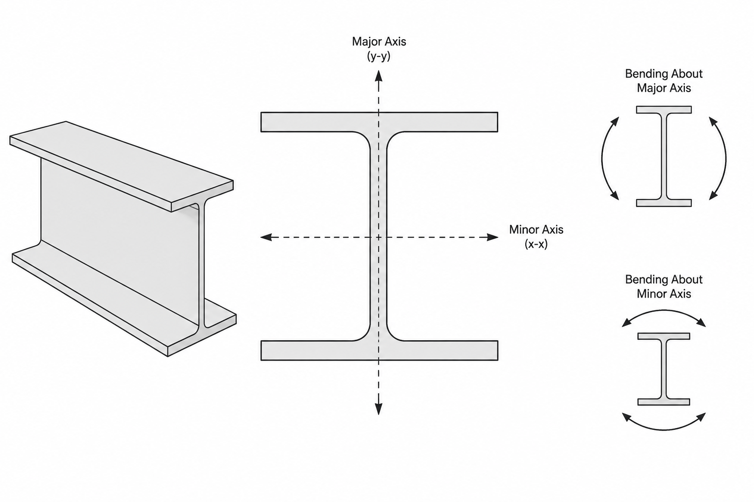
A cross section’s strong axis is generally the centroidal axis about which the section has the larger moment of inertia. Its weak axis is generally the centroidal axis with the smaller moment of inertia. These may also be called the major and minor axes.
For a typical W-shape in its familiar upright orientation:
- The horizontal centroidal axis is commonly identified as the x-x axis.
- Bending about x-x is strong-axis or major-axis bending.
- The vertical centroidal axis is commonly identified as the y-y axis.
- Bending about y-y is weak-axis or minor-axis bending.
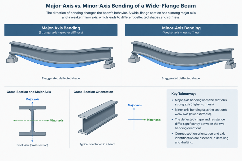
This convention must be interpreted carefully. Bending about an axis refers to the axis around which the cross section curves; it does not identify the direction in which the member runs. A horizontal beam can experience major-axis or minor-axis bending depending on its cross-sectional orientation and loading.
Why a W-Shape Is Much Stiffer About One Axis
In major-axis bending of a W-shape, the flanges are located relatively far from the x-x axis. Material farther from the axis contributes strongly to moment of inertia, so the flange arrangement produces substantial flexural stiffness.
For bending about the y-y axis, much of the section is closer to that axis. The same steel area therefore provides less moment of inertia in that direction. This is why an upright W-shape is usually much stiffer against vertical beam deflection than against sideways bending.
The relationship can be summarized conceptually as:
- Larger moment of inertia: greater elastic flexural stiffness about that axis.
- Larger section modulus: lower bending stress for the same elastic bending moment, all else being equal.
- Larger radius of gyration: a more favorable geometric distribution for certain stability checks about that axis.
These properties answer different questions and should not be treated as interchangeable. Moment of inertia relates directly to elastic stiffness, section modulus relates to bending stress, and radius of gyration is commonly used when evaluating member slenderness.
Section Properties Associated with Each Axis
| Property | Major-axis form | Minor-axis form | Typical use |
|---|---|---|---|
| Moment of inertia | Ix | Iy | Elastic stiffness and deflection calculations |
| Elastic section modulus | Sx | Sy | Elastic bending stress |
| Plastic section modulus | Zx | Zy | Plastic bending resistance calculations when applicable |
| Radius of gyration | rx | ry | Slenderness and stability evaluation |
Subscripts in a shape database should be read together with the displayed axis diagram. Although x and y are widely used for section axes, drafting and analysis software may use different local-axis labels or orientations. Never assume that a software model’s local axes match a printed shape-table sketch without checking.
How the Concept Changes by Shape Type
W-Shapes and Other Doubly Symmetric I-Shapes
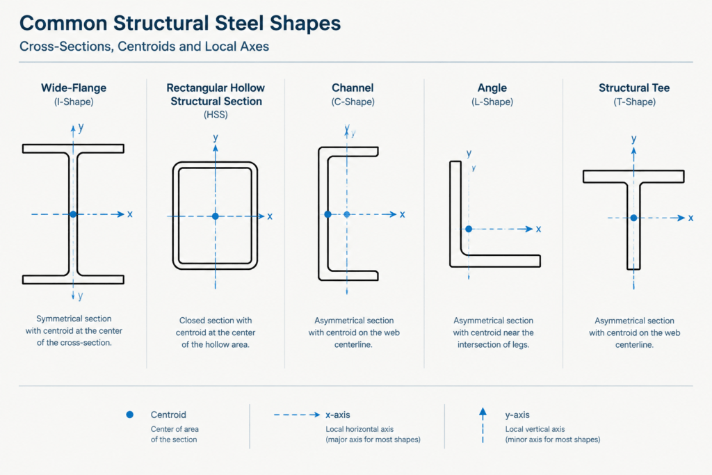
W-shapes provide the clearest example because both centroidal axes are also symmetry axes. The major and minor axes are readily visible, and the tabulated x-axis and y-axis properties correspond to these familiar orientations.
Even so, a W-shape’s strong cross-sectional axis does not eliminate stability concerns. An unbraced compression flange, member twist, connection flexibility, and loading away from the shear center can affect behavior. “Strong axis” should not be interpreted as “automatically stable.”
Rectangular and Square HSS
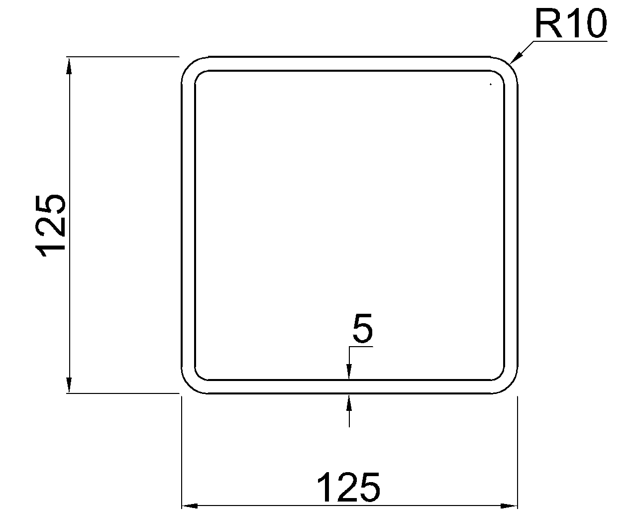
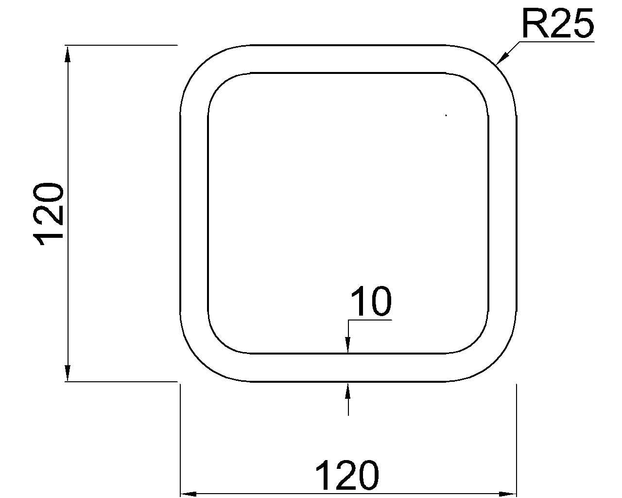
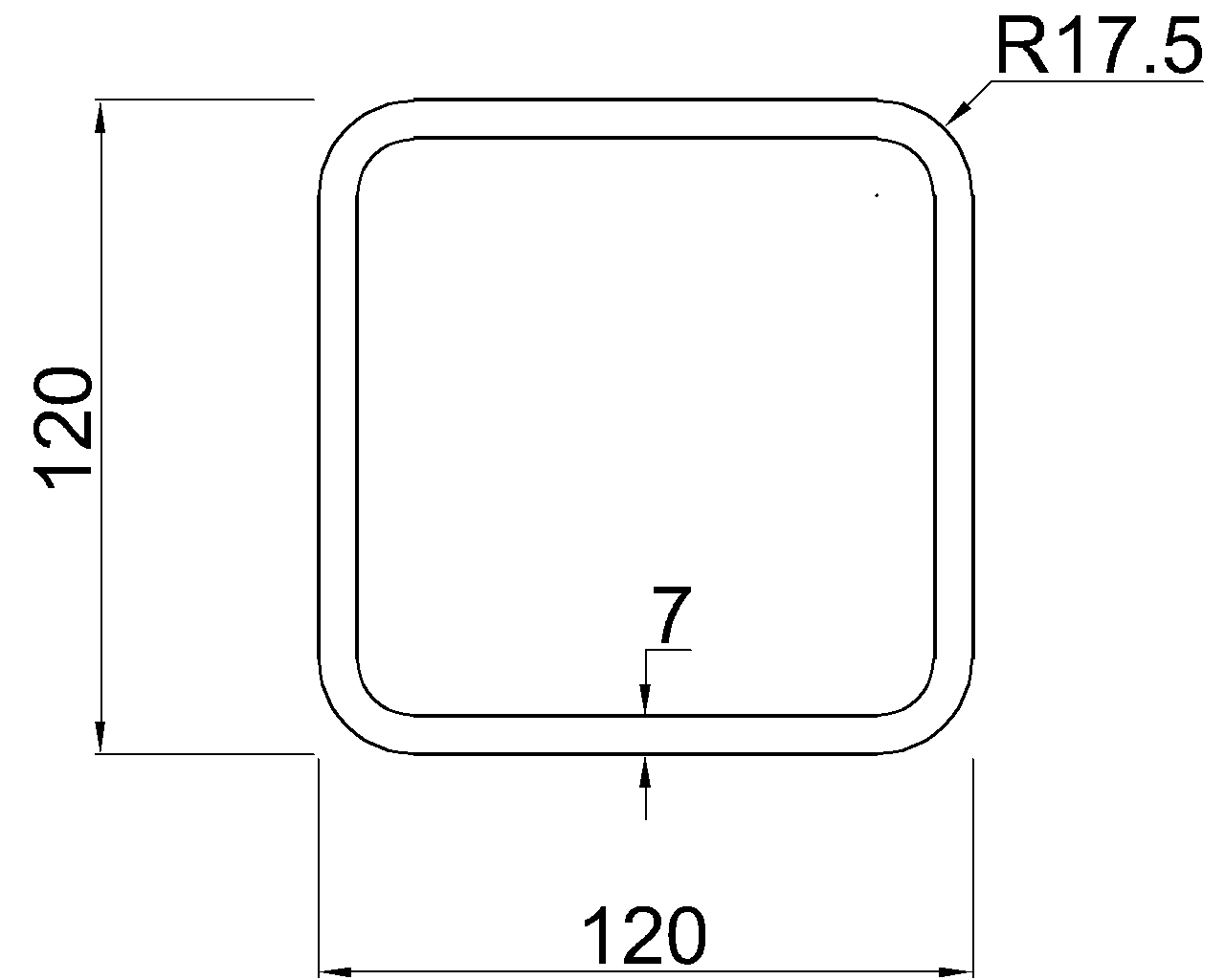
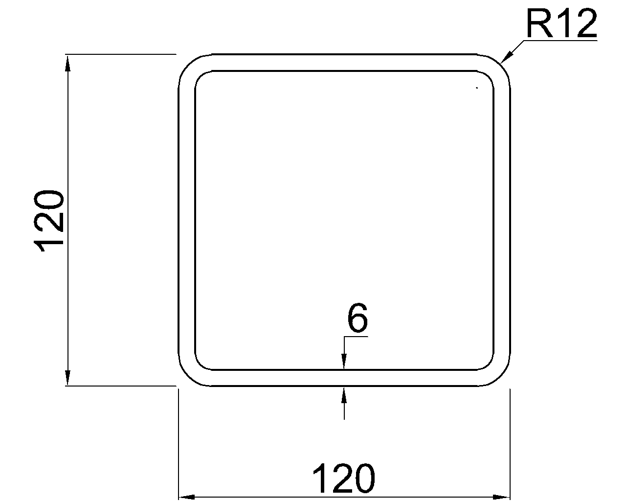
A rectangular HSS usually has a major and minor axis based on its outside orientation. When the longer cross-sectional dimension is vertical, it commonly provides the larger moment of inertia for the bending orientation normally intended for a beam.
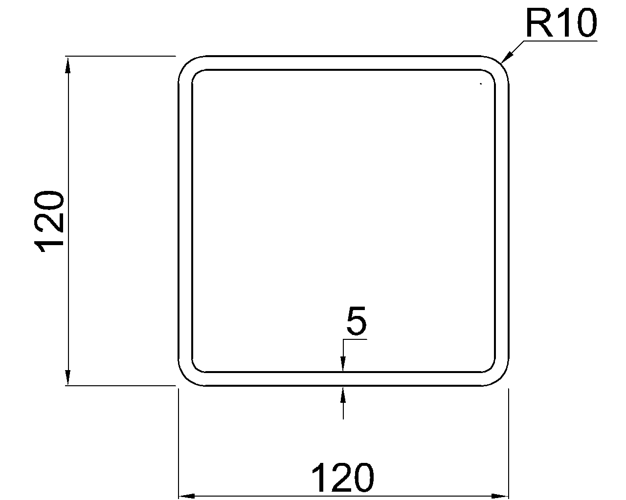
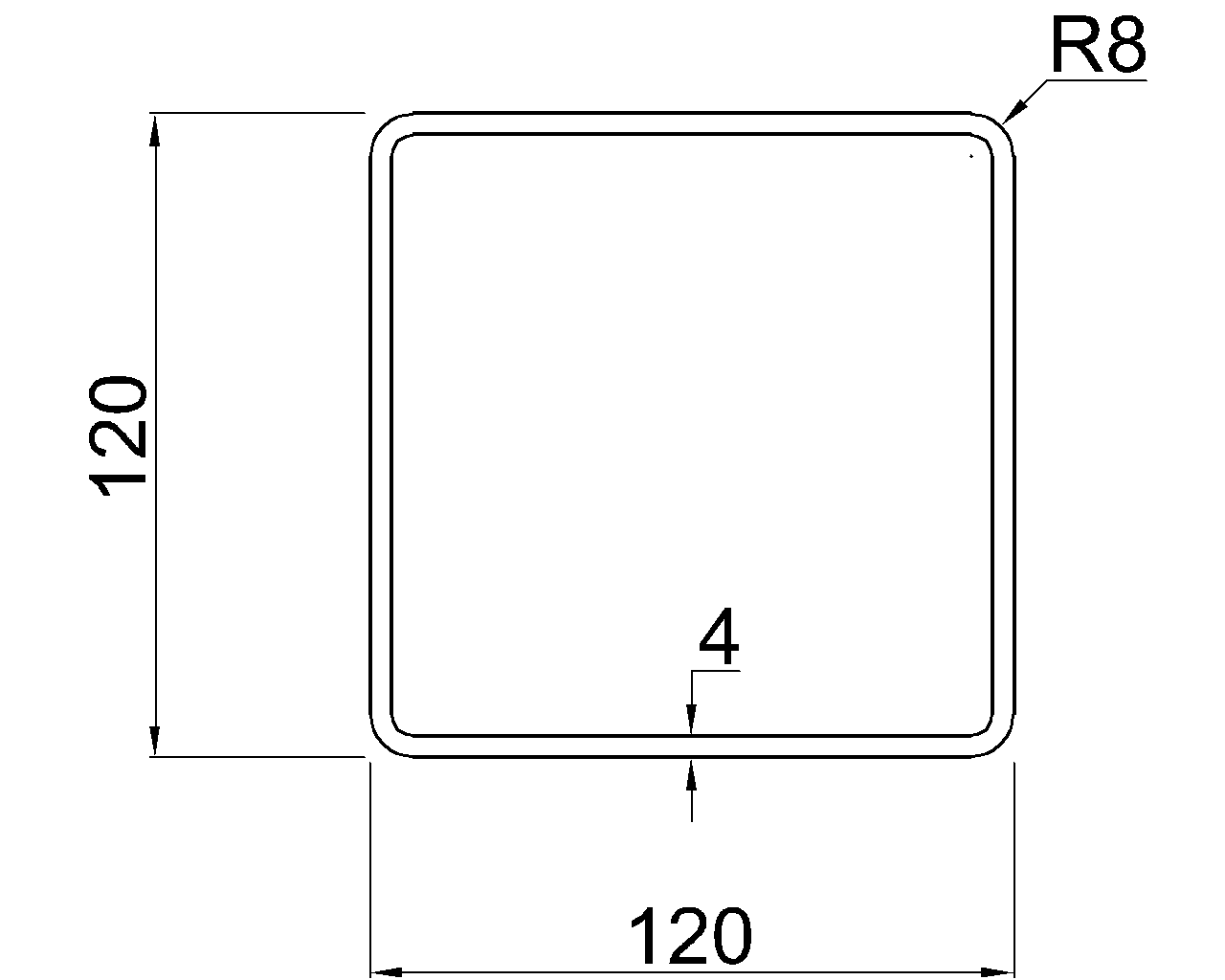
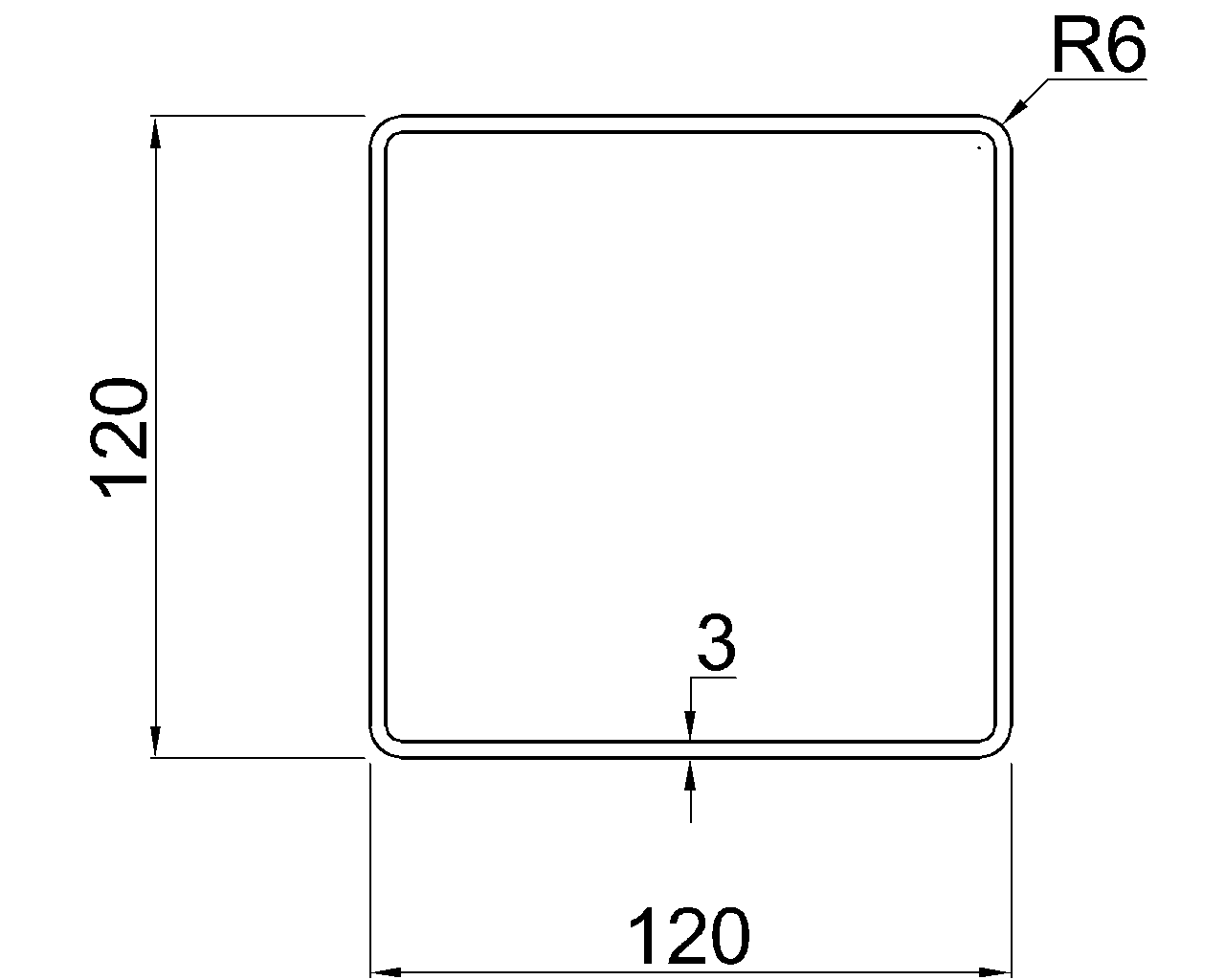
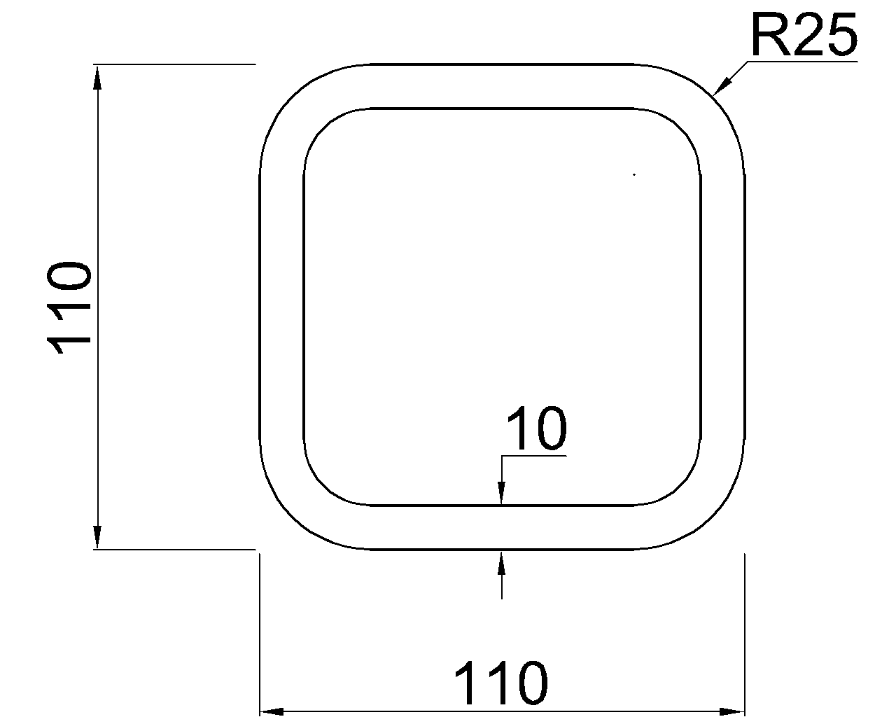
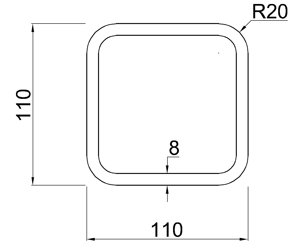
A square HSS has equal geometric properties about its two centroidal symmetry axes. In that limited cross-sectional sense, neither orthogonal axis is weaker than the other. Actual member behavior can still differ because of end conditions, connection details, load direction, holes, attachments, or system bracing.
Channels
A channel has a major and minor principal direction, but it is not doubly symmetric. Its centroid does not lie at the center of the overall flange width, and its shear center is offset from the web. Loads and connections that do not account for this geometry can introduce twisting as well as bending.
In drafting, avoid placing a channel by overall bounding-box center unless that is specifically intended. Model and dimension it from a meaningful reference such as the web face, back of channel, centroidal line, or connection work point.
Angles
Angles require additional care because their principal axes are generally rotated relative to axes parallel to the legs. Properties reported about geometric x and y directions may not describe pure bending about the principal axes. Products of inertia and principal-axis properties can become relevant.
An angle connected through one leg may also experience eccentricity between the load path and the centroid. A simple “strong leg up” description is not a complete representation of angle behavior.
Structural Tees
A structural tee is symmetric about one axis but not the other. Its centroid is displaced toward the flange rather than lying at half the overall depth. Tee orientation therefore affects not only strong- and weak-axis bending but also connection eccentricity, stem behavior, and the location of applied loads relative to the centroid and shear center.
Strong Axis Does Not Mean Stronger in Every Situation
Cross-sectional properties are only one part of member behavior. A member may have a large major-axis section modulus and still be governed by another condition. Relevant considerations can include:
- Unbraced length and lateral support
- Compression-member slenderness about each axis
- Lateral-torsional behavior of beams
- Local behavior of flanges, webs, or HSS walls
- Load eccentricity and connection geometry
- Torsion and the location of the shear center
- Openings, copes, notches, holes, and attached components
- End restraint and the stiffness of the surrounding framing
For example, a column may buckle about its minor axis because its radius of gyration is smaller in that direction. However, the governing direction cannot be identified from the section alone; effective length, bracing, and boundary conditions also matter.
Reading Orientation Correctly on Structural Drawings
A beam line on a framing plan usually shows the member’s longitudinal centerline, not its flange width or web direction. The section mark, typical framing convention, connection details, and model orientation establish how the shape is rotated.
Useful orientation checks include:
- Confirm whether the web is vertical, horizontal, or skewed.
- Check whether a channel is shown toe-in or toe-out.
- Verify which leg of an angle is connected.
- Identify whether a rectangular HSS is oriented tall side vertical or wide side vertical.
- Locate the flange and stem when detailing a structural tee.
- Compare local member axes in the analysis model with the axes used in the shape-property source.
Terms such as “rotate,” “web horizontal,” or “long side vertical” should be stated explicitly when the usual orientation is not intended. A shape designation alone generally identifies the section size, not its rotation in the completed structure.
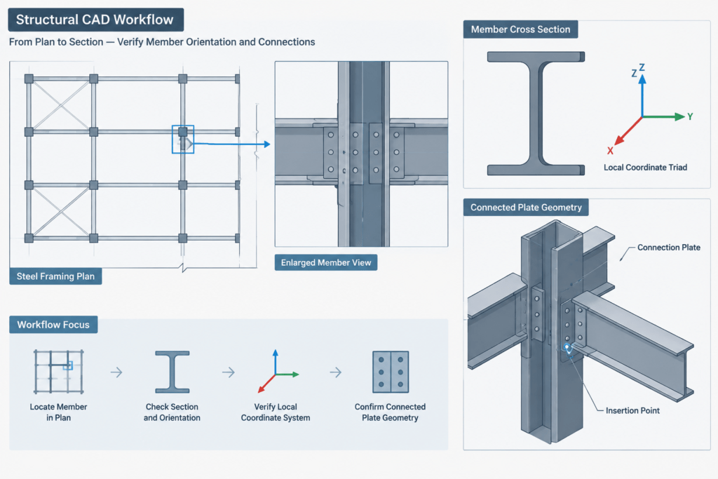
A Practical CAD and Modeling Workflow
- Start with a verified section profile. Use reliable dimensions and do not scale a profile from a screenshot or schematic.
- Establish a consistent insertion point. Depending on the task, this may be the centroid, web centerline, back of channel, outside face, or a connection work point.
- Draw local axes in a reference layer. Temporary x, y, and member-axis graphics help expose rotation mistakes.
- Assign the intended orientation. Confirm the web, flanges, HSS long side, angle legs, or tee stem in the relevant view.
- Check software conventions. Local axes, principal axes, object insertion axes, and global drawing axes may not coincide.
- Review connected geometry. Beam seats, clip angles, plates, bolt groups, weld lines, and offsets can reveal an incorrectly rotated member.
- Annotate unusual rotations. Do not rely solely on a visually narrow plan symbol to communicate section orientation.
Key Takeaway
The strong axis is generally the centroidal axis associated with the larger moment of inertia, while the weak axis is associated with the smaller value. For W-shapes this distinction is visually straightforward, but channels, angles, tees, and rectangular HSS require closer attention to symmetry, centroid location, principal axes, and torsion.
When using a steel-shape database, read Ix, Iy, Sx, Sy, rx, and ry together with the section sketch. When drafting or modeling, verify that the physical orientation and software local axes match the intended structural behavior. That simple coordination step prevents many section-property, connection, and detailing errors.