A steel channel can be simple to recognize but surprisingly easy to orient incorrectly in a drawing or model. Unlike a W-shape, a channel is not symmetric about both principal axes. Turning the open side, aligning the back of the web, or selecting the wrong insertion point can move connection surfaces and attachments even when the member size and length remain unchanged.
Clear steel channel orientation therefore requires more than a shape designation. Plans, elevations, sections, details, and CAD models must collectively show which way the flanges point, what geometric reference controls the member location, and where connected material is placed.
Basic channel orientation terminology
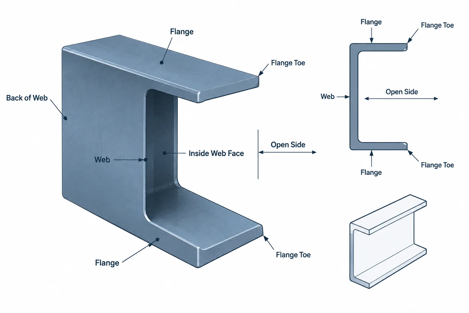
A rolled channel has a web and two flanges extending from the same side of that web. The following terms provide a practical vocabulary for describing its orientation:
- Web: The plate-like central portion spanning between the flanges.
- Back of web: The exterior web face opposite the projecting flanges. It is often used as a bearing, attachment, or layout surface.
- Inside web face: The web face located between the flanges.
- Flange toes: The free edges of the channel flanges.
- Open side: The side toward which the flanges project and the flange toes face.
- Channel depth: The overall dimension across the two flanges, conventionally treated as the vertical section dimension when the web is shown upright.
- Flange width: The projection measured across the channel from the back of the web toward the flange toes, subject to the dimensional conventions used by the applicable shape table.
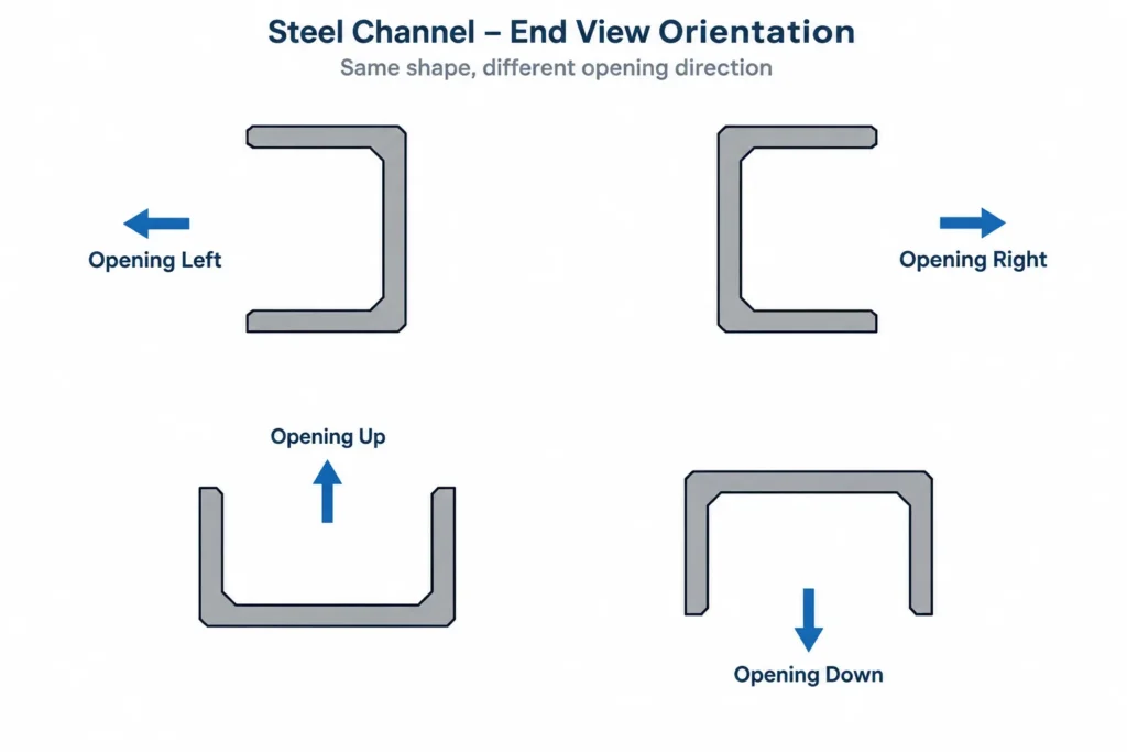
Statements such as “toes left,” “toes right,” or “open side toward grid line” are often more useful than a generic instruction to rotate the channel. They describe the result visible to a fabricator or checker rather than relying only on model coordinates.
Why a centerline alone may not locate a channel
A channel has one axis of geometric symmetry through its depth, but it is not symmetric between the back of the web and the flange toes. Its centroidal axis in that direction does not coincide automatically with the web centerline, back face, or midpoint of the overall flange projection.
This distinction matters when a member line is used to place the section in CAD. Depending on the project and software workflow, that line might represent:
- the section centroid;
- the centerline of the web;
- the back face of the web;
- a grid or support line;
- a bolt line or connection work line; or
- a user-defined insertion point with no structural meaning.
If the intended reference is not identified, two users can place the same channel designation at different physical locations while believing that both models are correct. A reliable detail should connect the controlling dimension to a recognizable face, centerline, or work point.
Reading orientation in plans, elevations, and sections
Plan views
In plan, a horizontal channel may be represented primarily by its member edges. Hidden lines, flange outlines, or an end section can help establish whether the open side faces inward, outward, toward a slab edge, or toward another framing member. A single centerline and designation may not communicate this reliably.
Elevations
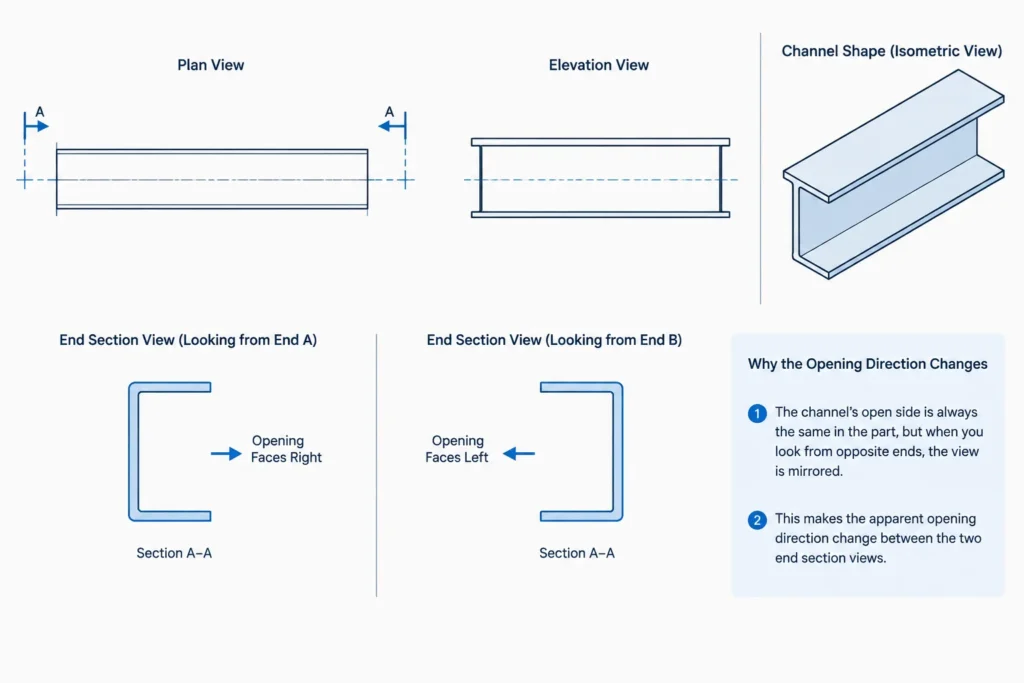
An elevation looking at the back of the web can make the channel resemble a rectangular strip unless flange edges or a section marker clarify the profile. An elevation looking into the open side may show both flange toes and the inside web face. The viewing direction is therefore essential.
Section and end views
An end view is usually the clearest way to document channel rotation. It directly shows the web, flanges, and open side. The section should still be coordinated with the viewing arrows: a channel that opens right when viewed from one end appears to open left when viewed from the opposite end.
This apparent reversal is a drawing-view issue, not necessarily a model error. Checkers should confirm the section cut direction before concluding that the channel has been mirrored.
Common channel orientation arrangements
| Arrangement | Typical geometric reference | Items to verify |
|---|---|---|
| Single channel with vertical web | Back of web, web centerline, or centroidal work line | Direction of open side and attachment access |
| Single channel used flat | Top or bottom flange surface, support line, or centroid | Which flange is up and whether drainage or debris traps are created |
| Channels back-to-back | Web faces, spacer centerline, or assembly centerline | Web spacing, fillers, fasteners, and access between webs |
| Channels facing each other | Overall assembly centerline or outside web faces | Clear space between toes and access inside the built-up assembly |
| Channels oriented the same direction | Common support face or repeated layout line | Whether both members use the same face offset and connection side |
These descriptions define geometry only. They do not establish structural adequacy, connection capacity, or whether a built-up arrangement behaves as intended. Those matters require project-specific design and connection information.
Connection and fabrication consequences
Reversing a channel can change much more than its appearance. The back of the web commonly provides a comparatively direct surface for contact with plates, supports, or other framing. The open side introduces flange projections that can affect tools, bolts, weld access, and the placement of attached parts.
Before finalizing orientation, review:
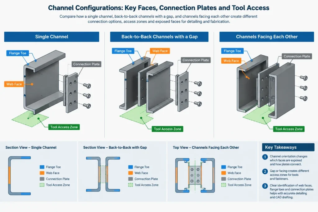
- Bolt installation access: Confirm that heads, nuts, washers, and tightening tools can reach both sides of the connected material.
- Plate fit: Check whether a plate bears against the web back, fits between the flanges, or conflicts with flange-to-web fillets.
- Weld access: Verify that the specified joint can be reached and that adjacent flanges do not obstruct the intended weld location.
- Supporting-member clearance: Look for conflicts between channel toes and beam flanges, column faces, stiffeners, deck edges, or other attachments.
- Assembly sequence: A detail that is geometrically possible in the finished condition may be difficult to bolt or weld in the required fabrication or erection sequence.
- Drainage and coating access: Upward-facing channels and enclosed paired arrangements may require project-specific consideration of water, debris, venting, and surface treatment.
Connection requirements should determine orientation where orientation affects the load path or attachment geometry. A drafting preference should not override the engineered details.
C shapes and miscellaneous channels are not interchangeable outlines
Standard channels and miscellaneous channels use different designation series and may have different proportions. A generic channel symbol is useful for diagrams, but it should not be treated as the exact outline of every rolled channel.
When fit depends on flange projection, web thickness, fillets, or other profile geometry, use verified data for the specified shape. Do not create one approximate channel block, scale it to a nominal depth, and assume that the resulting flange and web geometry represents another designation.
A practical CAD placement workflow
- Identify the controlling reference. Determine whether the member is located from its centroid, web centerline, web back, support face, or another project datum.
- Insert the verified section profile. Use shape data appropriate to the exact designation rather than a visually similar generic outline.
- Set the open-side direction. Confirm orientation in an end view before extending or extruding the member.
- Apply offsets deliberately. If the work line differs from the CAD block insertion point, use a documented offset instead of dragging the shape by eye.
- Check multiple views. Review plan, elevation, end section, and a three-dimensional view where available.
- Add connection material. Model or draw plates, bolts, weld extents, and supporting steel to expose access and interference problems.
- Label orientation where ambiguity remains. A short note identifying the open side or web-back reference can prevent a mirrored interpretation.
Channel orientation quality-control checklist
- Does the designation identify the intended channel series and size?
- Is the viewing direction of every section unambiguous?
- Is the open side visible or described?
- Does the controlling dimension terminate at the intended face or work line?
- Is the CAD insertion point understood?
- Are centroid, web centerline, and web back being treated as different references?
- Do plans, elevations, sections, and model views show the same orientation?
- Are paired channels shown with their required spacing and relationship?
- Have flange-to-plate, fillet, bolt, weld, and tool-access conflicts been reviewed?
- Would a reader looking from the opposite end mistakenly interpret the channel as reversed?
Key takeaway
Steel channel orientation should be defined by visible geometry and a clear locating reference. The shape designation identifies the section, but it does not say which way the channel opens or whether the member is controlled from its centroid, web centerline, or web back. Showing the open side, section viewing direction, and connection surfaces makes channel details easier to model, check, fabricate, and erect.